


1166 55
2211 00
G
INSTRUCTION MANUAL
Single language version and parts diagrams can be
down loaded from www
.keencut.co.uk
KC-ST/7298 JAN 13
MyBinding.com
5500 NE Moore Court
Hillsboro, OR 97124
Toll Free: 1-800-944-4573
Local: 503-640-5920

1 Contents 1
2 Packing list
2.1 Unpacking your machine
3 Assembly
3.1 Preparing the Legs
3.2 Preparing to fit the Squaring arm
3.3 Fitting the Squaring arm
3.4 Fitting the Pull Bar (210 only)
3.5 Fitting the Wall mounting bracket
3.6 Fitting the Free standing kit (165 only)
3.7 Fitting the Free standing kit (210 only)
3.8 Fitting the Back panels
3.9 Fitting the Handle
4 Squaring
4.1 Checking your machine for squareness
4.2 Adjusting the squareness
5 Calibration
5.1 Calibrating the Vertical square
5.2 Calibrating the Squaring arm scale
5.3 Fitting the Sight-line strip
6 Operation
6.1 Using the Clamp
6.2 The Cutting Head in General
6.2.
1 The Cutting Head in General
6.2.2 How to use the Pull Bar System
6.3 The Cutting Blade
6.3.
1 The Cutting Blade
6.3.2 Changing the Cutting Blade
6.4 The Scoring Blade
6.5 Glass Cutting (Optional)
6.6 The Twin Wheel (TW) Cutter
6.6
1 Changing the Twin Wheel (TW) Cutter
MyBinding.com
5500 NE Moore Court
Hillsboro, OR 97124
Toll Free: 1-800-944-4573
Local: 503-640-5920

1. Main body
2. Squaring arm
3. Left Back Support
4. Right Back Support
5. Long Back Support Screws
6. Short Back Support Screws
7. Back Support Fixing Block
8. Left Production Stop
9. Right Production Stop
10. Wall mounting bracket
11. M8 Screws and Washers
3
4
8
p
o
j
j
k
l
7
6
5
2 1
9
2.1 Unpacking your Machine 2.1
n
m
r
q
12. Spare blades
13. Main Handle
14. Hexagon wrenches 2.5, 3.0, 4.0, 5.0, 6.0mm
15. Spare Sight-line Strip (165 – 1 off, 210 – 2 off)
16. Vertical Scale
17. Optional Free Standing Kit
(Supplied separately – for 165 version only)
18. Pull Bar (210 only)
YOU WILL ALSO NEED:
17mm Spanner x 2
13mm Spanner x 1
210 only

NOTE: When taking the machine from the box ensure at least two people are lifting.
Remember to bend your knees and keep your back straight - this machine is heavy.
1. LEFT LEG - Slacken the bottom two screws and extend the telescopic leg to the
desired length. (This can be readjusted later). Tighten the screws to clamp
in position.
2. RIGHT LEG - Slacken the top and bottom screws in the Squaring Adjustment Block,
extend the telescopic leg by the same amount as the left leg and r
e-tighten the
screws.
3. Swing both legs out as far as they will go.
The first stages of assembly are carried out with the machine laying on the floor.
1
2
3 3
3.1 Assembly 3.1
Preparing the Legs
SteelTraK 210 only

3.2 Assembly 3.2
Preparing to fit the Squaring Arm
1. Remove the following:
A. One screw and spacer from each leg.
B. Two sets of hexagon headed bolts, washers and nuts from the Main Body
2. Lay the Squaring Arm flat adjacent to the machine, position the two long hexagon
nuts into the two large middle holes.
AA
BB
1
1
1
2
3
MyBinding.com
5500 NE Moore Court
Hillsboro, OR 97124
Toll Free: 1-800-944-4573
Local: 503-640-5920

3.3 Assembly 3.3
Fitting the Squaring Arm
1
2
2
3
5
4
1. Remove the Squaring Adjuster Block from the right hand Leg by releasing the
middle screw only (take note how this is fixed in place as it will replaced after the
Squaring Arm has been fitted)
2. Slide the Squaring Arm in through the gap in the Main Body and screw the two
hexagon bolts and washers in place loosely (3 or 4 tur
ns will do).
3. Fit the screws with spacers through the Squaring Arm into the legs, put the screws
all the way in but do not tighten at this stage.
4. Move the cutting head to its lowest position.
5. Refit the Squaring Adjuster block by firstly sliding the steel bar into the opening in
the Squaring Arm, then align the heads of the two scr
ews in the Leg to fit the top and
bottom holes in the adjuster block. The screws fixing the Squaring Arm to the
machine should still be loose and allow it some movement to help alignment. Insert
and tighten the screw in the middle hole.

3.4 Assembly 3.4
Fitting the Pull Bar (210 only)
The SteelTraK 165 offers a fast, accurate and robust way to cut boards measuring up to
165cm (65”). The SteeltraK 210 utilises a ‘Pull Bar System’ to increase the cutting
length to 210cm (82”) without compromising the straightforward way the SteelTraK cuts
medium size boards. The ‘Pull Bar’ is only used when cutting between 165cm and
210cm and is automatically stowed out of the way when not in use by virtue of its
integral spring balance
At any stage of the assembly before standing the machine up, fit the Pull Bar using a
6mm Allen key:
1. Remove the Screw and Stub Shaft from the end of the Pull Bar.
2. Insert the end of the Pull Bar in the bracket as shown ensuring the handle at the
other end is facing in the corr
ect direction.
3. Insert the Screw and Stub Shaft and tighten.
2
1
3
MyBinding.com
5500 NE Moore Court
Hillsboro, OR 97124
Toll Free: 1-800-944-4573
Local: 503-640-5920

3.5 Assembly 3.5
Fitting the Wall Mounting Bracket
NOTE A: If you are going to fit the Free Standing Kit (optional) turn to the next page.
NOTE B: Ensure the wall is stable and use the appropriate fixings.
1. Lift the top end of the machine (place it on a strong stool or chair) and fit the two
M8 scr
ews (supplied separately) through the black Top Bracket into the back of each
of the Legs. Tighten these and the adjacent two screws (four screws in all) to fix the
Legs to the top of the Main Body.
2. Fit the Wall Mounting Bracket to the top of the Main Body, fasten the screws
finger tight only
.
3. Get help to lift the machine up and position it against the wall in the desired position.
4. The Wall Mounting Bracket should lay flush against the wall. Mark the position of the
two V's on each side of the bracket with a short pencil.
5. Move the machine away and remove the Wall Mounting Bracket.
6. Attach the bracket to the wall in the marked position with appropriate fixings then
reposition and fasten the machine to the bracket.
2
3
4
5
6
4
1
NB.
SteelTraK
210 only

3.6 Assembly 3.6
Fitting the Free Standing Kit (optional 165 only)
NOTE: The Free standing kit is an optional extra and does not come packed
with the main machine. Assistance will be needed to fit the Free Standing Kit
1. Extend the telescopic leg to the same length as the front legs less 12cm (5")
2. Get help to hold the machine vertical and attach the bracket to the top of the
machine using the nuts and screws provided.
3. Swing down the stay and attach the fixing block to the plate on the bottom of the
Main Body
, tighten all three screws on the stay.
4. Adjust the telescopic leg so the machine stands evenly as shown.
5. Secure the top of the Legs to the Main Body by fitting the two M8 screws (supplied
separately) through the black plate into the back of each of the Legs, tighten these
together with the adjacent two scr
ews (four screws in all) to fix the Legs in position.
1
2
3
4
5

3.7 Assembly 3.7
Fitting the Free Standing Kit (optional – 210 only)
NOTE: The Free standing kit is an optional extra and does not come packed
with the main machine. Assistance will be needed to fit the Free Standing Kit
1. First carry out the fitting procedure (1 to 5) on the previous page.
2. Attach the bracket to the end of the Squaring Arm as shown using the two
bolts provided.
3. Adjust the telescopic leg so the machine stands evenly as shown.
3
2
MyBinding.com
5500 NE Moore Court
Hillsboro, OR 97124
Toll Free: 1-800-944-4573
Local: 503-640-5920

3.8 Assembly 3.8
Fitting the Back Supports
1. Tighten the two sets of nuts and bolts fixing the Squaring arm two the Main Column of
the machine.
2. Tighten the two screws to clamp the Squaring Arm to the two Legs.
3. Separate the Supports into left hand and right hand.
NOTE: The screws fit into special grooves in the underside of the Supports. The
gr
ooves have teeth on their sides to match the teeth of the screw thread, the screw can
be fitted in the groove anywhere along its length but be careful to make sure the screw is
kept perpendicular to the Support and not screwed in out of line.
4. Place one of the 16 Long Screws in each of the holes along the legs of the machine,
fix each Support in tur
n ensuring the ends of the Supports are firmly against the Main
Column and the screws are aligned with the special grooves as explained above.
5. Fix the end of each Support in position with the Brackets and short screws as shown.
1 1
2 2
3
4 5

3.9 Assembly 3.9
Fitting the Handle
1. Remove the three screws from the top of the Cutting Head and fix the Handle in
place being sure it is the correct way round (as shown). Move the cutter head to
the middle of the Main Body
1
MyBinding.com
5500 NE Moore Court
Hillsboro, OR 97124
Toll Free: 1-800-944-4573
Local: 503-640-5920

4.1 Squaring 4.1
Checking your machine for Squareness
For your machine to produce accurate square cuts the Squaring Arm needs to be
fixed at exactly 90° to the Main Column. to adjust the Squaring Arm first select a
sheet of foam core or foam board (3-6mm) at least 60cm x 100cm (24” x 36”) in
size. The larger the board the greater the accuracy.
1. Place the board on the machine
vertically as shown and apply the
clamp ensuring the bottom edge is in
firm contact with the Squaring Arm.
2. Select the cutting blade on the rotating
cutting head (see section 6). Cut into
the top of the board to produce a cut
approximately 3cm (1") long. Disengage
the cutter using the cutter r
elease lever.
Lower the cutter and make a similar cut
at the bottom of the board by pressing
the blade through the board about 3cm
(1") from the bottom edge of the board.
3. Unclamp and turn the board around and
place it back in the SteelT
rak but do not
clamp it.
NOTE: For the test to work the board
must be tur
ned laterally (like a page in a
book) not top to bottom.
Move the sliding head down and align
the board so that the cutting blade
enters the previous made cut at the
bottom edge of the board. Apply the
clamp. Release the blade..
4. Raise the sliding head and depress the
blade so that it engages with the top
edge of the board, if the machine is
squar
e the blade will enter the same cut
as made previously. if not refer to the
following page to make the necessary
adjustment.
1 2
4
3
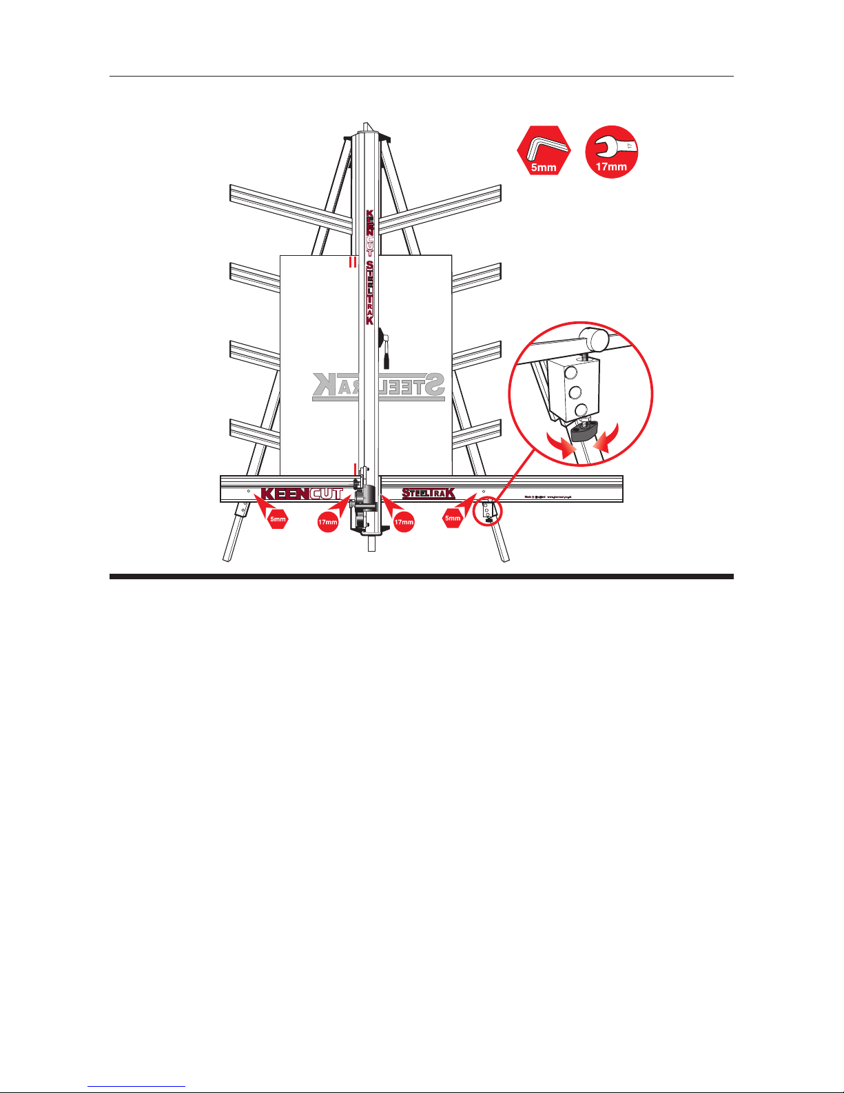
4.2 Squaring 4.2
Adjusting the Squareness
NOTE: Before making any adjustments carry out the squareness check as described on
the previous page.
It is assumed that the board used for the test is still clamped in the machine. From the
test results determine if the last cut made in the top of the board is to the left or right of
the previous cut, as shown above:
1. Slacken the two screws(1 + 4) joining the Squaring Arm to the two Legs.
2. Slacken the left hand nut (2) joining the Squaring Arm to the Main Body, make sure
the right hand nut (3) is tight.
3. Release the clamp and position the board such that the blade is held in the cut on
the bottom edge of the boar
d, press down on the board to make sure it is in good
contact with the Squaring Arm.
4. Turn the squaring adjustment knob (5) on the right hand Leg in the direction shown
below dependant upon the position of the top two cuts.
If the second cut is to the right of the first cut turn the adjustment screw clockwise
when viewed from underneath.
If the second cut is to the left of the first cut turn the adjustment screw counter-
clockwise when viewed from underneath.
The adjustment screw should be moved so that when the blade is moved to the top of
the boar
d it cuts between the two existing cuts, the plastic sightline fixed to the
edge of the clamp gives an indication where the machine is going to cut.
5. Repeat the squareness check.
6. Tighten the screws (1,2, & 4) nut loosened in 1& 2 above.
2 3
5
1 4

5.1 Calibration 5.1
Calibrating the Measuring scales
The vertical measuring scale is supplied separate from the machine, the two horizontal
squaring arm scales are already attached to the machine but may not be positioned
accurately and will need calibrating.
Vertical scale: This measures the height of the board on the machine and is only used
for r
eference.
1. Take a small piece of board and accurately measure its' height, place the board in the
machine such that it lays over the groove where the scale is to be applied.
2. With a pencil, mark a fine line level with the top edge of the board adjacent to the
groove.
3. Remove the release paper fr
om the groove in the Main Body and stick the Vertical
scale in place such that the pencil mark lines up with the measured dimension in (1).
1
2
3

5.2 Calibration 5.2
Calibrating the Measuring scales
The two horizontal squaring arm scales are already attached to the machine but may not
be positioned accurately and will need calibrating.
Horizontal scales: The SteelTrak can be loaded from either side and the scales are
used by eye or using the stops to measur
e the required width of board that will be cut
off to the left or right of the cut line. the cutting blade, twin wheels and scoring tools cut
on the same line. the measuring scales are fixed to sliding stainless steel strips that can
be moved to allow accurate calibration.
1. Slide the two Measuring Stops onto the Squaring Arm being careful to align the pro
file of the stop and its locking bar to the profile of the Squaring Arm. The Measuring
Stops ar
e able to 'flip' in and out as required.
2. Set both stops at 15cm (6"), 'flip' one of the stops into place and the other out, then
place a piece of card in the machine and slide it to touch the stop that is flipped in.
Clamp the car
d in place select the cutting blade on the rotating cutter head and cut
the card.
3. Measure the cut width of the card, say it is 14.7cm (5 7/8"), slide the Measuring Scale
so that it r
eads the dimension measured i.e. 14.7cm (5 7/8"). Repeat the process
with the other Measuring Stop.
NOTE: If the scales move too freely it is simple to increase the friction. To avoid resetting the scales first choose any easily r
emembered dimension and set the stop. Slide the
scale from its groove, twist it and replace it to the remembered dimension.
1
1 2
1

5.3 Calibration 5.3
Fitting the Sight-line strip
The Sight-line strip is fixed to the clamp and then trimmed using the cutting blade to give
an accurate guide when cutting to trim lines, the edge of an image or pencil marks.
NOTE: Do not engage the Twin Wheel Cutter until reading its instructions for use in
Section 6. Engaging the T
win Wheel Cutter interferes with the Sight-line Strip and can
cause damage to it. A gap is left in the Sight-line Strip at a convenient height to enable
the Twin Wheel Cutter to be engaged.
1. Remove the worn Sight-line Strip by peeling it off and clean any surplus adhesive with
solvent cleaner on a cloth. Remove the backing paper and starting at the bottom
pr
ess the Strip firmly in the channel provided working upwards and cut off at a
convenient height. Leave a gap of 18cm (7”) and then fit the remainder of the strip.
For the 210 version one full length Strip and one cut in half will be required.
2. Place a piece of firm board up to 6mm (1/4") thick on the machine to bridge the gap
running down the back of the Main Body, this needs to be the full height of the
clamp.
3. Place a piece of card or foamboard 3-6mm (1/8"-1/4") thick under the full length of
the flexible part of the Sight-line strip, not under the aluminium clamp itself.
Depr
ess the clamp handle so that the Sight-line strip is pressed flat across the surface
of the board.
4. Keep fingers clear and using a block or tool hold down the top left corner of the strip
to start the cut. With the turr
et rachet disengaged (Scoring page 6) press the blade
lightly on to the surface of the Sight-line strip score along the full length. Repeat and
trim the Sight-line strip in 2 or 3 cuts.
NOTE: If a board is not available to go the full length of the clamp use two or more
pieces or trim the strip in stages.
NOTE: The Sightline Strip is fitted to your machine but may wear or get marked with
use. A spare strip is included with the machine, replacement strips are available
from your distributor.
1
3
4
2

6.1 Operation 6.1
Using the clamp
The Clamping system enables the operator to control the grip pressure by means of an
integral friction brake that maintains the clamping force at the pressure applied by the
operating lever. Soft materials can be held firmly without sustaining damage and solid
materials held rigidly without movement. By following the guidelines below it will help
you to get the most from the machine:
USE CLAMPING INSTRUCTIONS
Soft materials such as Use light to medium pressure. The underside of the clamp
Foamcore boards, grips an area nearly 4cm (11/2”) wide with a non-marking
Lightweight card, etc. sponge rubber reasonable force can be applied. If in doubt
clamp a sample first with the good surface facing outwards.
Harder materials such as PVC Use medium to heavy pressure.
foam board, MDF or Composite
boards such as Dibond.
Cropping to trim lines, Place material in approximate position under clamp, apply light
pencil marks, etc. clamp pressure to allow the material to be repositioned. Align
(See drawing) the trim marks with the edge of the Sight-line strip and clamp.

6.2 Operation 6.2
The Cutting Head in General
The Cutting Head runs up and down
the Main Body of the machine on two
stainless steel tracks and has zero side
movement giving perfect blade control.
The Main Body also encloses a balance
weight system that allows the Cutting
Head to be suspended at any height,
benefiting blade changing and
maintenance but also minimising the
effort required to lift the heavy duty
Cutting Head.
There are four cutting functions built into
the machine the top part of the Cutting
Head houses the Twin Wheel or TW
Cutter, the standard Composite TW
Cutter is used for cutting tougher
materials than a normal blade can
handle. Composite boards such as
Dibond (r) and other materials including
MDF, Masonite and Hardboard up to
4mm thick are all cut with ease in one
stroke. The TW cutter can be easily
engaged and disengaged at will.
An optional Aluminium TW Cutter is also
available for cutting aluminium up to
1.6mm (16swg) and can be attached to
the machine in just a few seconds. If you
need further advice regarding materials
please contact your supplier.
On the lower half of the Cutting Head is
the Multi-Cutter Head housing three
instantly selectable cutting tools. To
change between the cutting tools just
pull the Turret Handle
out to the left and rotate it one third of a
turn until the indicating label shows
which cutter is active.
The Multi-Cutter Head also incorporates the unique Keencut Ratchet System which
gives two main advantages. Firstly, it enables thick, tough materials to be cut in multiple
passes by setting the ratchet to cut through the board in stages giving the best cut
quality achievable and reducing operator effort to suit the operator. Secondly, it locks
the cutting blade at the required depth and holds it there mechanically so concentration
can be applied to pushing the blade through the material without having to worry about
applying effort to hold the blade in the material. Once the blade reaches the bottom of
the cut it the ratchet is automatically disengaged and the Cutting Head moves out to its
rest position ready to be set for the next cut.
MyBinding.com
5500 NE Moore Court
Hillsboro, OR 97124
Toll Free: 1-800-944-4573
Local: 503-640-5920

6.21 Operation 6.21
The Cutting Head in General
The three cutting tools are:
1. The Cutting Blade - Using a standard Medium Duty utility blade (not Heavy Duty -
they will not fit) to cut PVC Foamboar
ds like Forex®, corrugated plastic such as
Correx®, card, matboard and many other types of rigid boards up to 13mm (1/2")
thick.
2. The Scoring Blade - A specially designed tool steel scoring blade is used to score
the surface of any brittle plastics including Acrylic's such as Perspex®, Plexiglass
and even some Polycarbonates. Once scored the plastic sheet is removed from the
machine and 'snapped' along the score line. Any thickness (up to 13mm 1/2") can
be scor
ed but tests should be carried out on a sample of the sheet to ensure it does
'snap' and to an acceptable quality (remember to use hand and face protection when
doing this).
3. Glass Cutting - A high quality tungsten carbide wheel is used to score glass. An
optional Glass Cutting Kit will be r
equired to use this facility, operating instructions for
glass cutting are not included in this manual and but are supplied with the Glass
Cutting Kit.
NOTE: Our research established that glass cutting is very rarely required by Sign makers
and Graphic workshops. That knowledge allowed us to exclude the fixed br
eakout ramp
and incorporate a level back board system enabling material to be loaded from left or
right for optimum material flow in any workshop.
1
2
3

6.22 Operation 6.22
How to use the Pull Bar System
Cutting boards above 165cm high is done so in two stages, the first using the Pull Bar
then disengaging the Pull Bar and using the handle directly connected to the Cutting Head.
To cut larger than about 165cm (65”):
1. Raise the Cutting Head to chest height, select the cutting tool required and engage it
in position r
eady for cutting.
2. Check the black plastic handle on the Pull Bar is pointing out towards you.
3. Push the Cutting Head up far enough so the stub shaft on the Pull bar can be twisted
to engage in the slot of the handle bracket (see above).
4. Using the Pull Bar push the Cutting Head to the top of the machine.
5. Insert the material to be cut into the machine and clamp in position.
6. Pull down on the Pull bar to cut, the stub shaft is designed so that it locks itself in
position when the Cutting head is moved up or down preventing the Pull bar from
being able to twist out of place.
7. When the board has been cut as far as the Pull bar will allow, slightly push the Pull Bar
up and twist it away from the Cutting Head to disengage it. Raise the Pull bar all the
way up to its r
est position
6. Continue the cut using the Cutting Head handle in the normal way.
3

6.3 Operation 6.3
The Cutting Blade
Basic Cutting Technique. Select the Cutting Blade position on the turret and clamp the
material in the machine.
1. Move the cutting head beyond the top of the material to be cut.
2. Press to engage the cutter.
Draw the cutter down to the bottom of the machine where it will disengage
automatically.
3. Should you engage the cutter by mistake or for any reason want to disengage the
cutter without moving it to the bottom of the machine pull down the Ratchet
Release Lever.
2
1
3
MyBinding.com
5500 NE Moore Court
Hillsboro, OR 97124
Toll Free: 1-800-944-4573
Local: 503-640-5920

Ratchet Latch
The unique 'Ratchet Latch', enables thick dense materials (such as PVC foam board) to
be cut easily in stages. Count the number of 'clicks' to position the blade just below the
surface of the material to make your first cut then add an extra 'click' for the second and
subsequent cuts.
1. Pull down the Ratchet Release Lever to disengage the ratchet if required.
As a rough guide when cutting PVC foam boar
ds:-
Using the Blade Support Plates
The two support plates either side of the blade are designed to give maximum rigidity of
the blade when cutting har
d or dense materials.
To adjust the support plates swing down the cutter guard by undoing the guard locking
knob.
2. Turn the turret 1/2 turn until blade is pointing towards you, unlock the blade clamping
scr
ew, the support plates can be adjusted by sliding the black pin in the slot. Move
the plates to suit the material.
For cutting most materials the support plates can be set about 12mm (1/2 ”) from the
blade tip.
THICKNESS TAKE
3mm (1/8”) Initial surface cut + 1 additional cut
5mm (1/4”) Initial surface cut + 1 or 2 additional cuts
10mm (3/8”) Initial surface cut + 3 or 4 additional cuts
1
2
6.31 Operation 6.31
The Cutting Blade
The blades used are
'Medium Duty Utility Blades'
as shown above.

6.32 Operation 6.32
Changing the Cutting Blade
Changing the Cutting Blade
Unlock and swing down the cutter guard, rotate the turret so the cutting blade is
facing towards you.
3. Undo the blade clamping screw a number of turns to release the blade.
4. Change or turn over the blade, insert it back into the turret as far as it will go.
Tighten the blade clamping scr
ew
, the safety pin will engage to hold the blade in
position. At this point the position of the Blade Support Plates can be adjusted to
suit the thickness of material being cut, further tightening of the screw will clamp the
blade firmly in position.
Rotate the turret back to the cutting position. Replace the guard ensuring it is locked
closed.
3 4
MyBinding.com
5500 NE Moore Court
Hillsboro, OR 97124
Toll Free: 1-800-944-4573
Local: 503-640-5920

6.4 Operation 6.4
The Scoring Blade
The scoring blade is designed to score Acrylics, Plexiglass and other similar rigid
plastics. Trials should be carried out on scrap materials first to ensure you obtain the
required standard of cut.
Scoring/Breaking Technique
Select the Scoring Blade position on the turret and clamp the material in the machine.
1. Disengage the Ratchet. Depress the Ratchet Lever and pr
event it from engaging when
released by depressing the rachet Lock Button. The Multi-cutter will move freely.
2. Clamp the target plastic in the machine. Starting at the top using a thumb depress the
Multi-cutter head so that the blade touches the plastic at the top.
3. Apply thumb pressure to the cutter and draw the blade down the material in one
continuous motion.
Remove the plastic fr
om the machine and snap it by hand.
CAUTION: USE GLOVES AND SAFETY GLASSES WHEN SNAPPING PLASTIC
Changing the Scoring blade
Unlock and swing down the cutter guard, rotate the turret so the scoring blade is facing
towar
ds you.
4. Release the blade clamping screw. Eject the blade using the black ejector pin
5. Replace the blade to the right of the clamping plate, push the blade in as far as it
will go and tighten the blade clamping scr
ew.
Rotate the turret back to the cutting position. Replace the guard ensuring it is
locked closed.
1 2
3 4
5

6.5 Operation 6.5
Glass Cutting
An optional Glass Cutting Kit will be required to use this facility, operating instructions for
glass cutting are not included in this manual but are supplied with the Glass Cutting Kit.
MyBinding.com
5500 NE Moore Court
Hillsboro, OR 97124
Toll Free: 1-800-944-4573
Local: 503-640-5920

6.6 Operation 6.6
The Twin Wheel (TW) Cutter
The Twin Wheel Cutter is mounted on the upper part of the cutting head and is used
for cutting a range of tough, rigid materials. The standard machine is fitted with the
Composite TW Cutter and is used for cutting composite boards such as Dibond
®
and
other materials including MDF, Masonite and Hardboard up to 4mm. Many other softer
boards and card can also be cut, trials should be carried out to ensure the desired
quality of cut is obtained.
1. Engage the TW cutter by loosening the large hand knob (1/4 turn).
2. Depress the locking button and r
otate the cutter 90 degrees until the locking button
springs out to its rest position, tighten the hand knob firmly.
NOTE: The TW cutter will interfere with the Sightline Strip as it is being engaged, either
engage the cutter at the top end of the machine or cut away a portion of the sightline
strip at a convenient height (e.g. adjacent to the clamp handle) and move the cutter to
this position for engaging/disengaging.
3. Ensure the TW cutter is above the height of the top edge of the board, position the
material in the machine and apply the clamp.
4. Bring the twin wheel cutter down until it makes contact with the top edge of the
material and stop. T
ake a firm grip and then push the cutter down through the
material without stopping.
1
2
3
4

6.61 Operation 6.61
The Twin Wheel (TW) Cutter
The cutting wheels are made from high grade tool steel and are heat treated to give give
a long life but this is dependant upon daily use and the materials being cut. The signs of
the wheels wearing out are:
A rough finish predominately on the right hand side of the cut, with flaking on materials
such as MDF.
The board trying to turn under the clamp when being cut (also check the clamp
pressure).
Changing the twin wheel cutter
Hold the TW cutter onto the Cutting Head whilst unscrewing the large hand knob.
Once the hand knob has been r
emoved the TW cutter can be lifted free. Reverse the
procedure to fit the replacement TW cutter ensuring it is properly located against its
mounting plate before fastening the hand knob.
MyBinding.com
5500 NE Moore Court
Hillsboro, OR 97124
Toll Free: 1-800-944-4573
Local: 503-640-5920

7.11 Maintenance 7.11
Cleaning
Keencut design machines to be as maintenance free as possible, however we do
r
ecommend regular cleaning. Do not wipe the squaring arm channels or remove any
debris with fingers, as it may contain sharp particles such as glass. Use a vacuum
cleaner if possible or if a soft brush is used, work slowly and do not allow particles to
flick off of the bristles.
Lubrication
It is important that the correct lubrication is used as ordinary oils and solvents can
adversely affect plastics, the diagram above shows the best lubricants for the various
parts of the machine. Do not use penetrating oils for lubrication on this machine.
1. Guide rods and rollers
Wipe using cleaning solvent on a cloth, and lubricate the surfaces very lightly with
petr
oleum jelly. The axles of the rollers are lubricated and sealed for life and need no
further attention.
2. Ratchet system
Use a light oil (3 in 1), one or two drops on the pivot point and one drop on the
ratchet teeth
3. Balance weight
Silicon Lubricant sprayed in from the top of the balance weight opening whilst the
cutting head is parked at the top of the machine
4. Ratchet release bar
Smear edge with petroleum jelly
5. Swinging Arm
Petroleum jelly around curved slot.
3
ä
1
5
2
4
ä
ä
ä
ä
MyBinding.com
5500 NE Moore Court
Hillsboro, OR 97124
Toll Free: 1-800-944-4573
Local: 503-640-5920

7.12 Maintenance 7.12
The Clamp
Adjusting the Clamping Pressure
The pressure of the clamp is in relation to the amount of
pr
essure applied to the operating handle. However in
time the maximum clamping pressure can reduce due to
wear on the friction block (hidden within the machine),
compensation for this can be made by adjusting the two
small grub screws in the housing as shown. Turning the
screws clockwise until they stop moving them undoing
them one full turn should give an acceptable pressure,
but further small adjustment can be made to increase or
decrease the pressure as required. Care should be taken
not to tighten either grub screw fully or this will result in
undue wear of the friction plate.
Clamp Alignment
When cutting tough materials it is essential that the
clamping system operates at its' optimum, the moving
clamp bar must press evenly onto the boar
d being cut
and not clamp it only at the top or bottom.
1. Open the clamp by at least 1-2mm and remove the
plastic cover strip situated above the clamp handle it just
clips out of place, use the end of a small steel rule to
lever it fr
om its' groove.
2. The clamp adjuster is at the top end of the push rod
and is locked in position by two locking nuts.
n The silver nut has a normal right-handed thread,
slacken it using a 10mm wrench by
turning it
counter-clockwise when looking from below.
n Now slacken the black nut, this has a left hand thread
and should be tur
ned clockwise when viewed from
below.
n The 'adjuster' is the hexagonal bar between the two
nuts, by tur
ning it with the spanner it alters the clamps
alignment with the back of the machine.
3. Rotate the adjuster whilst observing the clamp from
the side and bring the clamp into parallel.
4. To check for parallel use 2 pieces of A4 paper, place
one under the bottom end of the clamp and hold the
other at the top end whilst depressing the clamp
handle, check that the clamp firmly grips pieces
of paper
.
5. Tighten the two locking nuts whilst holding the
adjuster in position with the second spanner, then
operate the clamp a few times, check and adjust
further if necessary
.
6. Finally, replace the plastic cover strip.
1
2
3
ä
ä
ä
ä
ä

7.13 Maintenance 7.13
Guide Wheel Adjustment
The Cutting Head slides up and down on two stainless steel Guide Rails (1) that are
embedded into the Slideway (2). Ther
e are four grooved Guide Wheels that run on the
rails, the two furthest away are fixed (A) and the two closest are adjustable (B). These
Guide Wheels are adjusted in the factory and should not under normal circumstances
require re-adjustment. However, the adjustment check and procedure is listed in the
event that the Cutting Head needs to be removed for any reason:
Adjustment Check:
The steel bar with the oval holes, the Spring Block (4), holds the two adjustable wheels
and is designed to flex, a small amount, like a spring and add tension so the Guide
Wheels are pr
essed onto the Rails. It is important that the tension is set correctly, use
a 0.15mm (0.006") feeler gauge or a stout piece of paper to measure the gap under the
Spring Block as shown. If the gap is too large or too small the adjacent wheel will
need adjusting.
Wheel Adjustment:
The Shafts that the adjustable wheels run on are eccentric and move the wheel into or
away from the rail as it is rotated.
n Using a 13mm spanner on the Locking Nut and a 5mm spanner (or grips) on the
squar
e end of the Shaft hold the Shaft still and loosen the Locking Nut by about half
a turn.
n Rotate the Shaft clockwise whilst using a feeler gauge or paper as above to measure
the gap under the Spring Block. If the Shaft will not rotate any further and the corr
ect
gap has not been achieved, turn it anti-clockwise and the correct adjustment should
be obtained within one full rotation of the Shaft.
n When the correct gap appears hold the Shaft still and tighten the Locking Nut.
4
1
A
A
B
B

7.14 Maintenance 7.14
Planned Maintenance Chart
Frequency: After 2 weeks of use and then every month thereafter
Adjust clamp pressure (page 7.1
2.)
Check clamp alignment (page 7.1
2.)
Check guide wheel adjustment (page 7.13.)
Lubricate Guide rods & rollers (page 7.1
1.)
Lubricate Ratchet system (page 7.1
1.)
Lubricate Balance weight (page 7.1
1.)
Lubricate Ratchet release bar (page 7.11.)
Lubricate Swinging Arm (page 7.1
1.)
In the first few weeks the clamp with
bed itself in and will need adjusting.
See instructions on page 7.1
1.
Using 2 pieces of A4 paper, place
one under the bottom end of the
clamp and hold the other at the top
end whilst depressing the clamp
handle, check that the clamp firmly
grips both pieces of paper. If not the
clamp will need aligning as above.
This should never go out of adjustment but is wise to check.
Wipe using cleaning solvent on a
cloth, and lubricate the surfaces very
lightly with petroleum jelly. The axles
of the rollers are lubricated and
sealed for life and need no further
attention.
Use a light oil (3 in 1), one or two
drops on the pivot point and one
drop on the ratchet teeth
Silicon Lubricant sprayed in from the
top of the balance weight opening
whilst the cutting head is parked at
the top of the machine
Smear edge with petroleum jelly
Petroleum jelly around curved slot.
MyBinding.com
5500 NE Moore Court
Hillsboro, OR 97124
Toll Free: 1-800-944-4573
Local: 503-640-5920
 Loading...