

OVAL 6
INSTRUCTION MANUAL
Keencut – the world’s finest cutting machines

1 Contents 1
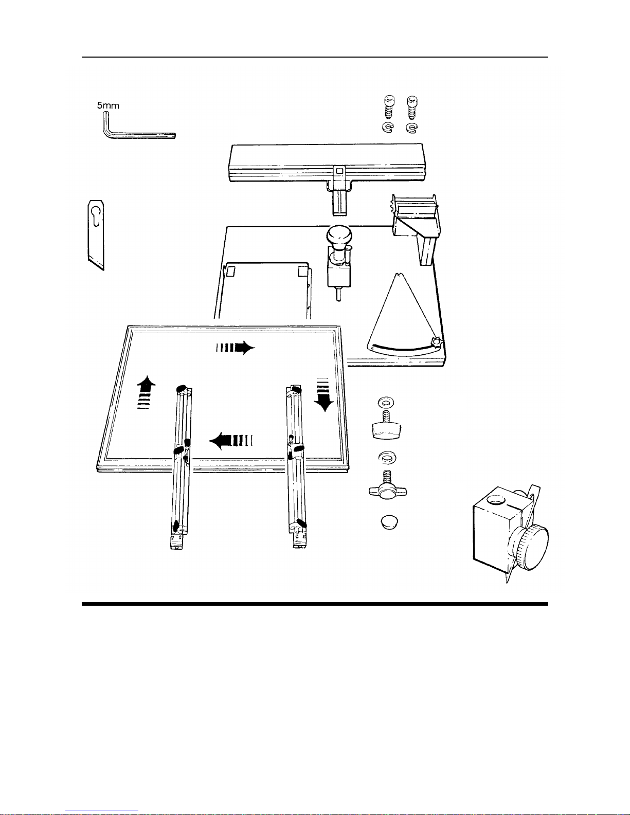
2 Packing list
2.1 Unpacking your machine
3 Assembly
3.1 Fitting the Beam and Cutting Head
3.2 Fitting the Tur ntable
3.3 Fitting the Clamp Bars
4 Operation
4.1 Setting the size of the oval/circle
4.2 Setting the blade depth and using the Clamps
4.3 Cutting an oval/circle
4.4 Calibrating the Scales
4.5 The Centre Pointer
4.6 Cutting small ovals and circles
5 The Craftsman Toolset (optional)
5.1 Embossing
5.2 Penlining
5.3 Cutting V-grooves
5.4 Cutting glass ovals/circles
5.5 Cutting glass ovals/circles (Cont’d)
6 Looking After Your Oval 6
6.1 Maintenance & Blades
Introduction
Thank you for choosing a Keencut Oval 6. Every effort has been made to bring you a
superbly built product with the promise of many years of good service. Please read
these instructions carefully in order to obtain maximum benefit from your machine and
remember, in case of difficulties ask your distributor or Keencut Limited for assistance.
Once familiar with the many functions of the Oval 6 and the advantages of the unique
turntable system, your own creativity will enable you to produce very satisfying and
individual work that is the hallmark of the successful framer.
2.1 Unpacking your Machine 2.1
9. M8 washer x 2
10. M6 thumbscrew x 4
11. M6 washer x 4
12. M6 screws x 2
13. M6 spring washer x 2
14. Blades
15. 5mm Hexagon wrench
16. Plastic feet x 6
1. Main Base
2. Beam
3. Turntable
4. Cutting Head
5. LH clamp bar
6. RH clamp bar
7. Bevel/vertical blade holder
8. M8 thumbscrew x 2
x 4
x 4
x 2
x 2
x 6
NOTE: Do not carry the machine by the Turntable or Beam.
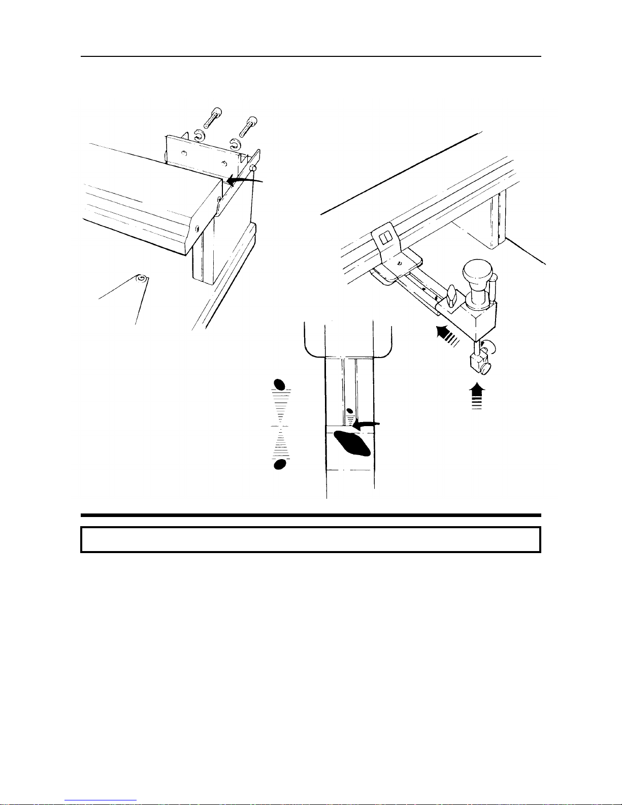
1. Attach the Beam to the hinge of the Main Base using the two M6 screws and
spring washers.
2. Ensure precise alignment of the Beam by positioning it carefully on the small
ledge of the hinge.
Tighten the two socket screws firmly using the 5mm hexagon wrench.
3. Fit the Cutting Head to the Beam by sliding it onto the bracket until the edge of
the aluminium block aligns with the centre of the ‘Lazy oval scale’ as shown.
Tighten the thumbscrew.
4. Fit the Blade Holder to the shaft on the Cutting Head and fasten it by tightening
the black plastic thumbscrew.
The machine is now set to cut ovals 10cm and larger. For smaller ovals see
‘4.6’.
3.1 Assembly 3.1
Fitting the Beam and Cutting Head
1. Line up the red arrow under the Turntable with the red arrow on the Main Base.
2. Place the Turntable with its four tabs inside the tabs of the Main Base and slide
the Turntable from left to right, the tabs will drop into alignment preventing the
Turntable sliding further.
3. Fit and tighten the four M6 thumbscrews and washers.
NOTE:
The optional MAXI Tur ntable attaches in the same way as the standard Turntable.
When cutting on the Oval 6 the blade tip runs on a sheet of glass this is not
supplied with the machine. Cutting on to a glass surface is the most safe, reliable and
economical method. A “self healing mat” can be used but the surface will deteriorate
rapidly when bevel cutting. A matboard cutting mat will quickly be destroyed and will
allow the blade to penetrate and damage the printed grid below.
CAUTION: USE EYE PROTECTION WHEN CUTTING GLASS
Cut a sheet of 3mm (
1
/8”) glass to the following size: (do not use 2mm glass)
Table type Size – metric Size – imperial
Standard 453 x 642mm 17
13
/16” x 251/4”
Maxi 642 x 802mm 25 1/4” x 319/16”
There is no need to polish the edges. Place the glass in the recess of the Turntable on
the printed grid.
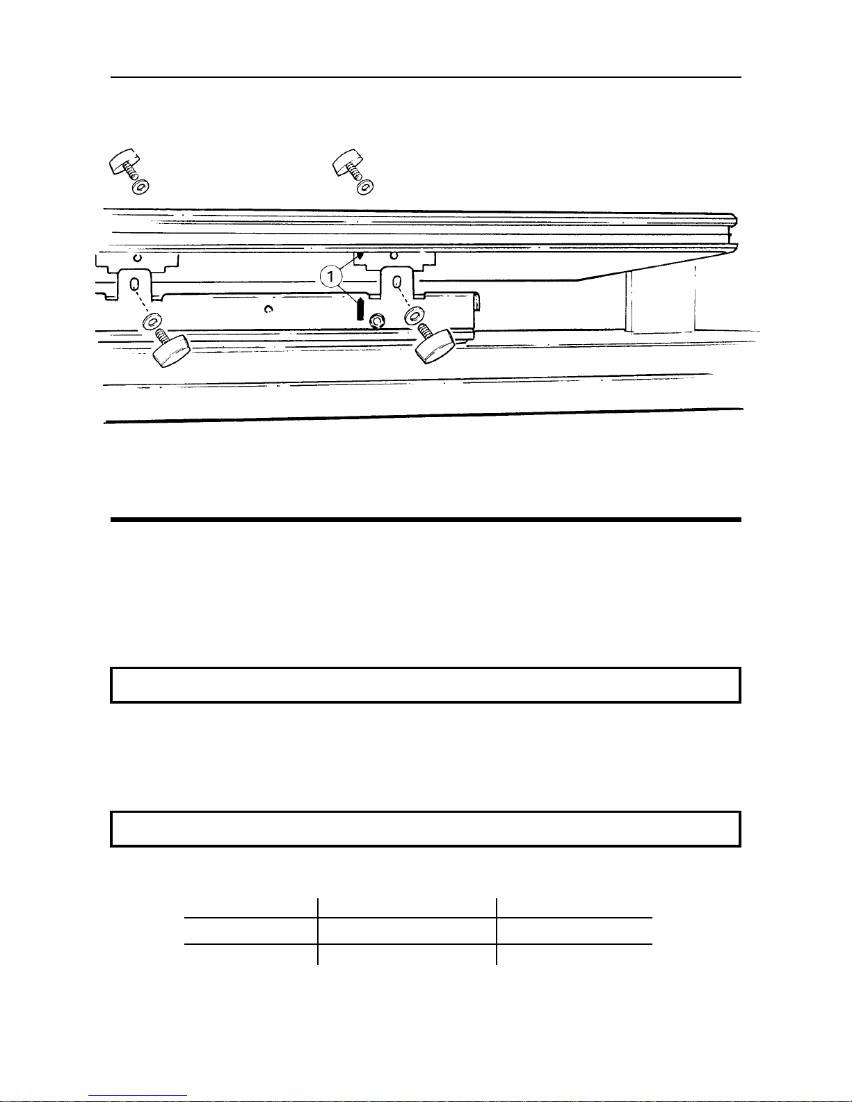
3.2 Assembly 3.2
Fitting the Turntable
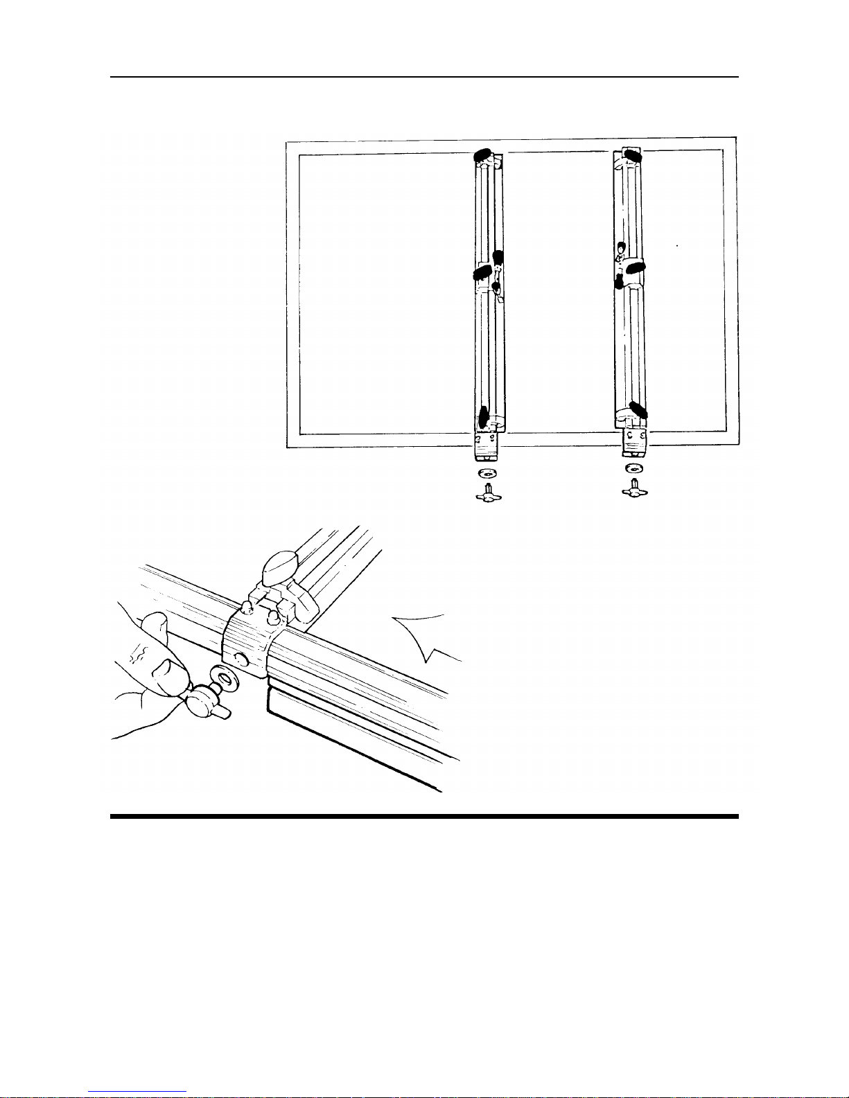
1. Find the two Sliding Nuts in one of the long edges of the Table.
2. Fit the two Clampbars to the Turntable using the M8 thumb screws and washers.
3.3 Assembly 3.3
Fitting the Clamp Bars

There are two scales that require setting dependant upon the size of the oval/circle:
1. The width of the oval (or diameter of the circle) is set on the beam scale by
squeezing the release lever and cutter head support then sliding the cutter until
the red line in the window indicates the required dimension. The scale can be
read in inches or centimetres.
Scale If the measuring scale itself slides too easily set the cutting head to
tightening 10 (cms. or ins.), slide the scale from its groove by about 10cm [4”]
and twist it to lightly distort the strip. Replace the scale and check
the friction, slide the scale to again read 10.
2. The difference between the width and length of the oval is set on the differential
scale, turn the knob counter-clockwise by half a turn to release and set to the
required dimension, lock in position. For a circle set the pointer as far to the right
as it will go (not necessarily the ‘zero’ on the scale). The scale will be set to either
inches or centimetres and can be changed by turning the scale over as follows:
3. Set the scale to zero and remove the two screws then remove the knob and
pointer. Turn the scale over and carefully refit the pointer ensuring the small pin is
located in the hole (as shown), refit the knob and loosely refit the two screws.
Adjust the scale so that it reads zero then moderately tighten the two screws.
If you find the machine does not cut accurately the scales require calibrating – refer to
the next section.
4.1 Operation 4.1
Setting the size of the Oval/Circle

1. Setting the blade depth
The blade should be set deep enough to penetrate the board being cut with a
clearance of approximately 1.5mm [
1
/16”] under the blade holder (thickness of
regular matboard).
a. Loosen the blade clamping knob and remove the old blade.
b. Place two thicknesses of matboard together on the turntable.
c. Lower the blade holder (by rotating the cutting head knob) leaving the blade
slots clear.
d. Fit the blade in the slot allowing it to drop so the tip touches the turntable
and tighten the blade.
NOTE: If the material being cut is thicker than regular matboard use a piece of the
material for the depth of cut and a piece of regular matboard to set the clearance.
2. The clamping system
The clamping system consists of two clamp bars each with two corner stops and
a toggle clamp. For small and medium size mats only two of the corner stops
positioned diagonally opposite are normally required (fig. 2a). For larger mats use
all four corner stops, for extra security the corner stops can be used as additional
clamps (fig. 2b.). The toggle clamps are adjustable to take different thicknesses of
board, turn the black rubber cap to adjust.
The scales on the turntable frame and the clamp bars are all set so that the ‘zero’
indicates the centre of rotation of the table. So, if a mat is centred in the clamps
according to the scales the oval will be produced in the centre of the mat.
2b
2a
4.2 Operation 4.2
Setting blade depth and using the clamps

1. Lift and park the beam to give easy
access to the turntable.
2. Set the two clamp bars to 10 either
side of the zero point on the table
edge scale. Set the corner stops to 8
on the clamp bars. Position the matboard coloured face up and clamp in
place using the toggle clamps.
3. Lower the beam. Set the width scale
to 10 and the differential scale to 4
(14-10 = 4), Twist and lower the
cutting head so the blade rests on
the eventual fallout.
4. Do not touch the cutting head knob
yet and rotate the turntable for
approximately
1
/4 of a turn to align
the blade.
5. Keep turning and smoothly apply
finger pressure to the top of the
cutting head knob, continue turning
until the fallout moves. Raise and
twist the knob to park the cutting
head.
NOTE: If the size of the oval does not reflect the sizes set refer to the next
section on ‘Calibrating the scales’
Vertical cutting
The vertical blade is of the same type as that used for bevel cutting (SM02 or SM03 for
small oval/circles) but held in a different slot in the blade holder. The blade depth is not
as critical but should be long enough to cut through the material without the base of the
blade holder touching the surface of the matboard and not so far extended that the
blade tip bends when cutting.
Use the same procedure as explained above, a cleaner cut will be produced by placing
the matboard in the machine coloured face down as the thickness of the vertical blade
can displace the edges of the cut upwards producing a small burr on the coloured edge.
4.3 Operation 4.3
Cutting an Oval/Circle
Bevel cutting The following refers to cutting a 14 x 10 oval centrally in a matboard
20 x 16 (cms. or ins.)

Small variations in cut dimensions can occur dependant upon the size and proportion of
the oval, in most cases the error is insignificant but care needs to be used when cutting
ovals below 10 cm [4”]. If in doubt check before cutting and correct as follows:-
Metric
For this example say an 8cm wide by 11cm long
oval is required:-
1. Set the width to say 1cm less than the
finished mat size ie. 7cm
2. Set the differential to the same dimension
as for the finished mat ie. 11cm-8cm. = 3cm.
3. Cut the oval in the normal way.
4. Measure the width of the oval, let us say
it is 7.2cm for example.
5. Compare the 7.2cm with the dimension
read on the width scale.
6. Slide the width scale (Not the cutting head)
until it reads 7.2cm.
7. Measure the length of the oval, let us say
it is 11.3cm, and calculate the difference
between it and the width measured
previously ie. 11.3cm-7.2cm = 3.1cm.
8. To correct the differential scale loosen
the two screws and the knob, swing the
scale until it reads 3.1cm, re-tighten the
screws and the knob.
9. Reset the machine to width = 8cm.
& difference = 3cm. Then cut the
finished oval.
Imperial
For this example say a 3” wide by 4” long oval
is required:-
1. Set the width to say 1/2” less than the
finished mat size ie. 21/2”
2. Set the differential to the same dimension
as for the finished mat ie. 4” - 3”. = 1”.
3. Cut the oval in the normal way.
4. Measure the width of the oval, let us say
it is 3 1/16” for example.
5. Compare the 3 1/16” with the dimension
read on the width scale.
6. Slide the width scale (Not the cutting head)
until it reads 3 1/16”
7. Measure the length of the oval, let us say
it is 4 “, and calculate the difference
between it and the width measured
previously ie. 4 “ - 3
1
/16” = 1 1/16”
8. To correct the differential scale loosen
the two screws and the knob, swing the
scale until it reads 1 1/16”, re-tighten the
screws and the knob.
9. Reset the machine to width = 3”. &
difference = 1” then cut the finished oval.
4.4 Operation 4.4
Calibrating the scales

1. Using the centre pointer
The centre pointer indicates the centre of rotation of the turntable to enable the
matboard to be placed without using the scales on the turntable. It is used for
precise positioning when cutting multiple openings. The centre pointer should be
pivoted into its park position under the beam when not in use.
NOTE: When using or setting the centre pointer always set the differential scale to the
circle setting or position the turntable at 90° to the beam (portrait position).
1.1 Mark the centre position of the oval or circle on the matboard.
1.2 Swing the centre pointer from under the beam until it stops.
1.3 Place the matboard so that the centre mark is under the centre pointer.
1.4 Move the clamps to secure the board and cut the opening.
2. Adjusting the centre pointer for accuracy
The printed turntable grid is correctly installed when the centre lines align with the
zero points on the turntable edge scales. The centre pointer should exactly
indicate the crossed centre lines on the turntable grid when the differential scale
is set to cut a circle or the turntable is in the ‘portrait position’.
Set the differential scale to the circle position and swing the centre pointer into
position. If the centre pointer appears to point to the centre of grid rotate the
turntable and check that it does so for a complete revolution. If it does not
proceed as follows:-
2.1 Lift the beam.
2.2 Observe the socket screw with an eccentric head
which limits the travel
of the centre finder. Fix the 5mm hexagon wrench to it and lower the beam.
2.3 Adjust the pointer laterally by tur ning the eccentric screw until the pointer is
at the centre of the grid.
2.4 If adjustment front to back is necessary first lift the beam and observe the
small screw
in the end of the pivot which locks the pointer in place. Fit
3mm hexagon wrench and loosen it.
2.5 Lower the beam and adjust the pointer until it is at the centre of grid, lock
the screw.
2.6 The height of the pointer can be adjusted using screw
.
4.5 Operation 4.5
The Centre Pointer

NOTE: When cutting very small ovals/circles better results can be achieved using the
more acute SM03 blade.
1. Small ovals
Distortions will occur when making very small diameter circles or ovals owing to
the self alignment action of the tools.
1.1 Note the position of the cutting head against the lazy oval scale.
1.2 Set the machine to make the desired size and cut the oval/circle.
If the top of the oval leans to the right move the cutting head towards the beam.
If the top of the oval leans to the left move the cutting head away from the beam.
1.3 Loosen the thumbscrew allowing the cutting head to move towards or
away from the beam.
1.4 Cut another oval in a different part of the board, check the setting and
repeat the adjustment as necessary locking the thumbscrew each time.
The machine is now set to produce upright ovals in the size range for which it was
adjusted. Over 10cm [4”] the ovals will remain upright throughout the range.
2. Small circles
When cutting small circles the effect of the self alignment action is slightly
different, the blade can become uncontrollable and very inaccurate. Moving the
cutting head towards the beam as explained above will correct it.
1.1
SM03
1.3
4.6 Operation 4.6
Cutting small Ovals and Circles

1. Cut an oval/circle of the desired size.
2. Do not alter the differential setting
but increase the oval/circle width
setting.
The ‘Craftsman Toolset’ includes two types of embossing tool:-
A half round edged wheel that produces a narrow embossed line
A flat edged wheel that produces a wide embossed line
A half round edged wheel A flat edged wheel
3. Fit the embossing tool and lower it
onto the matboard surface.
4. Do not touch the cutting head knob,
rotate the turntable by at least
1
/4 turn
to align the embossing tool.
5. Whilst turning apply firm pressure to
the cutting head knob and continue
for one or two turns until the indent
line is of the desired depth.
6. Remove the mat or leave it in place if
you wish to fill it with a pen line.
5.1 The Craftsman Toolset (optional) 5.1
Embossing

2. Penlining
Embossing an indent before drawing the penline provides a smooth surface for
the ink, prevents bleeding and ensures a reliable alignment for the pen. For most
lines the thin half round embossed indent is appropriate, for a very thick pen use
the broad flat embossing tool.
2.1 Ensure that the pen is drawing freely with no excess ink and that it is
accurately clamped in the pen holder. The tip should protrude 5-10mm
[
1
/
4” to
1
/
2“] below the bottom of the holder.
2.2 Do not change the width or differential settings after producing the
embossed indent.
2.3 Place a small sheet of thin paper on the mat so that one clean edge is
across the embossed line. Lower the pen until the tip is on the paper about
8cm [3”] from the paper edge.
2.4 Do not touch the cutting head knob at all - gravity is quite sufficient.
Rotate the turntable whilst holding the paper to align the pen tip.
2.5 The pen will run off of the edge of the paper and into the embossed indent.
Rotate the turntable slowly and consistently for at least two turns removing
the paper but do not stop turning.
2.6 Lift the pen whilst the tur ntable is still moving and twist the cutting head
knob to park it.
5.2 The Craftsman Toolset (optional) 5.2
Penlining

1. Cut an oval/circle of the desired size.
2. Do not alter the differential setting
but increase the oval/circle width
setting.
The initial hand pressure on the cutting head controls the speed of the blade entry in to
the mat surface and the continued pressure can affect the depth.
3. Fit the glass scoring tool and lower it
onto the matboard surface. Rotate
the table (without touching the cutting head knob) to align the tool then
press on the cutting head knob to
make a light indent 2cm [1”] or
so long.
4. Remove the glass scoring tool and fit
the V-groover.
5. Lower the V-groover and carefully
place the tips of the two blades in
the indent.
6. Place a hand on the cutting head
knob and rotate the turntable one full
revolution applying firm constant
pressure on the cutting head knob.
7. Stop when the blades stop cutting
the thin strip from the matboard.
Inspect the V-groove and remove the
finished mat from the clamps.
NOTE: The blade tips of the V-groove tool are set one behind the other but
when viewed from the cutting direction the tips should appear to meet exactly without
overlap. The V-groove width and depth may be changed by adjusting the nylon
screw in the centre of the blade holder. Two SM02 blades are used in the
V-grooving tool.
5.3 The Craftsman Toolset (optional) 5.3
Cutting V-grooves

1. Clamp a piece of matboard on the
turntable that is larger than the glass
blank do not lay the glass on it yet.
2. Set the width and differential scales to
the desired size of oval and fit the
glass scoring tool to the cutting head.
3. Lower the cutting head and with light
pressure score the oval shape on the
matboard.
WARNING: Wear eye and hand protection when handling glass.
4. Measure the scored shape to confirm
the accuracy.
5. Place the glass blank on the matboard and lower the cutting head
onto a small piece of paper or
thin card.
6. Rotate the turntable and apply finger
pressure only to the cutting head
knob, run the glass cutting wheel off
the paper, then whilst still applying
finger pressure remove the paper.
5.4 The Craftsman Toolset (optional) 5.4
Cutting glass Ovals/Circles

7. Rotate the turntable one complete
revolution only. Stop when the score
line joins up.
WARNING: Wear eye and hand protection when handling glass.
8. Tur n the glass over on the matboard
or a felt surface.
9. Press around the score line with the
thumb or tap it to make the cut.
10. Starting 1mm [
1
/16”] from the score
line score four radial lines to the outside edge.
11. Turn the glass over.
12. Starting at the edge press with the
thumb or tap to break each score to
remove the cut piece.
5.5 The Craftsman Toolset (optional) 5.5
Cutting glass Ovals/Circles

Blades
The Oval 6 has been designed to use standard craft knife blades:-
Material Operation use blade...
Regular matboard Cutting all except very small ovals/circles SM02
Regular matboard Cutting very small ovals/circles SM03
Thick matboard and foamcore Cutting all sizes of oval/circle SM03
All materials Cutting V-grooves SM02
Replacement blades and glass cutting wheels are available through your Keencut distributor or from Keencut direct.
Cleaning and Lubrication
● Clean the Oval 6 frequently with a damp or dry cloth and keep it covered when not in use.
Dirt can spoil your work
● Do not use solvents, they can harm the paint finish, remove silicone lubrication and effect plastic components.
● Lubrication. Use lubricant spray, apply it with a pad or cloth. Wipe off any excess liquid with a clean cloth.
● Do not use oil, grease or all-purpose penetrating oils and sprays. Silicone spray may be used on the operating
disc under the table if ever required.
Fault Finding
Fault Causes and Suggestions
Start/Finish mark - Hand Pressure applied to the cutting head before the turntable
had rotated to align the cutter
- Pressure applied to the cutting head too suddenly
- Blade depth not correct
Cutting needing more than two - Change Blade
revolutions on regular matboard - Apply more pressure
Poor finish on the bevel - Blunt or broken blade
- Insufficient hand pressure on the cutting head
Excessive blade wear or tip - Glass cutting surface scored
breakages - Blade depth incorrect
A double cut around part of - Blade depth incorrect
the bevel - Inconsistent pressure on the blade
- Not enough pressure on the cutting head during cutting
Extreme lazy ovals (not vertical) - Turntable rotating in the wrong direction
- Slide block wrongly set and adjusted (see ‘Cutting small ovals’)
Ovals or circles not centred - Scales not accurately set or adjusted on the clamp bars or
in matboard turntable edge.
V-groove not meeting up after - Blade tips need resetting to meet exactly when viewed from the direction
one revolution of cut. Please note that the blades are set one behind the other when
viewed from below.
The
Dexter No. 3
blade is also
suitable.
SM02
Glass
cutting wheel
SM03
6.1 Looking After Your Oval 6 6.1
Maintenance and Blades
 Loading...