


EXCALIBUR 3S Manual
Single language versions and parts diagrams can be down loaded from www.keencut.co.uk
Thank you for choosing the Keencut Excalibur 3S. Every
eort has been made to bring you a precision engineered
product with the promise of many years of valuable
service. In order to obtain maximum benet from your
machine please read these instructions carefully. For advice
and assistance or replacement parts please contact your
distributor or Keencut.
PLEASE NOTE THIS IS A TEMPORARY MANUAL

1
Contents
2 Packing List
2.1 Unpacking your machine
3 Assembly
3.1 Adjusting the legs
3.2 Preparing to t the squaring arm
3.3 Fitting the squaring arm
3.4 Fitting the support arms & wall mounting bracket
3.5 Attaching machine to wall with mounting bracket
3.6 Fitting the optional free standing kit
4 Squaring
4.1 Checking the machine for squareness
4.2 Adjusting the squareness
5 Calibration
5.1 Calibrating the vertical scale
5.2 Calibrating the squaring arm scales
5.3 Fitting the sightline strip
6 Operation
6.1 Using the clamp
6.2 The multi-tool cutter and the counterbalance
6.3 Using & changing the cutting blade
6.4 Cutting thick material using the ratchet latch
6.5 Using and changing the scoring blade
6.6 Using & changing the twin wheel cutter
7 Maintenance
7.1 General maintenance
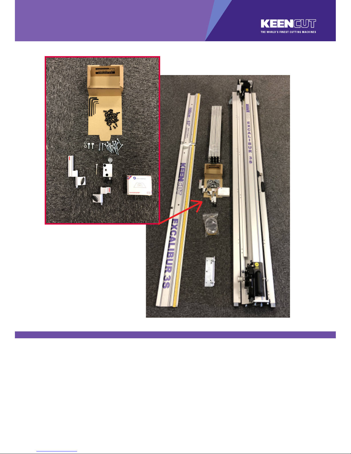
2.1
Unpacking your machine
NOTE: * When lifting the main body from the box, DO NOT lift using the black handles on the
cutters.
1. Main body *
2. Squaring arm
3. Left & right hand support arms
4. Vertical scale & spare sightline strip
5. Wall mounting bracket
6. Hexagon wrenches
2.0, 3.0, 5.0, 6.0 mm
7. Short support arm screws
8. Long support arm xing screws
9. Leg xing screws & washers
10. Left hand production stop
11. Right hand production stop
12. Squaring adjuster block & xing screw
13. Spare blades
❶
❸
❷
❹
❺
❻
❼
❽❾
❿
⓬
⓫
⓭
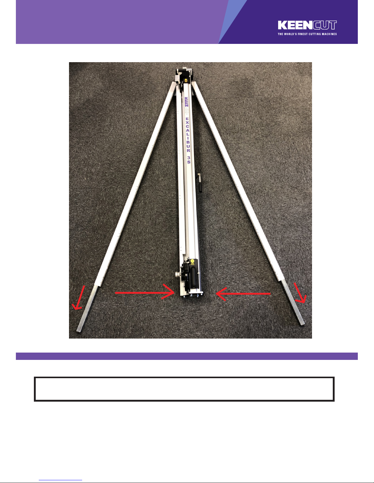
3.1
Assembly
The rst stages of assembly are carried out with the machine laying on the oor.
NOTE: When lifting the main body from the box do not lift using the black handles on the cutters.
DO NOT untie balance weight cord at this stage.
Remove the main body from the box and lay it on the oor, remove the packaging from the bottom
end.
1. Slacken the bottom two screws on each leg using the 5mm hexagon wrench and extend the
telescopic parts to the desired length. (These can be re-adjusted later before xing the
machine to the wall). Tighten screws rmly to clamp in position.
2. Swing both legs outwards as far as they will go.
Adjusting the legs
❶
❶
❷❷

3.2
Assembly
Preparing to t the squaring arm
1. Move the lower cutting head to the middle of the main body.
2. Remove the following:
A. One screw from each leg, using 5mm hexagon wrench.
B. Two sets of hexagon headed bolts, washers and nuts from the main body using 17mm
spanners.
C. Remove small screw and two washers from the back of the squaring arm using 3mm
hexagon wrench. (Right hand side ONLY).
Ⓐ
Ⓑ
Ⓒ

3.3
Assembly
Fitting the squaring arm
1. Slide the squaring arm in from the left hand side through the gap in the main body and align
the corresponding screw holes.
2. Fit the two hexagon bolts from the back of the main body, t the washers and nuts nger tight
only.
3. Fit the scews through the squaring arm into the leg using the 5mm hexagon wrench, do not
tighten fully.
4. Ret the squaring adjuster block by rstly sliding the steel bar into the opening in the squaring
arm, then align the heads of the two screws in the leg to t the top and bottom holes in the
adjuster block. The screws xing the squaring arm to the machine should still be loose and
allow it some movement to help alignment. Insert and tighten the screw in the middle hole.
5. Tighten the two hexagon bolts and screws as in 2 and 3 above.
6. Untie and release the balance weight cord, ensure the clamp is closed by pushing down on
the clamp handle then slide the both cutting heads to the bottom.
❶
❷
❸
❹
❺
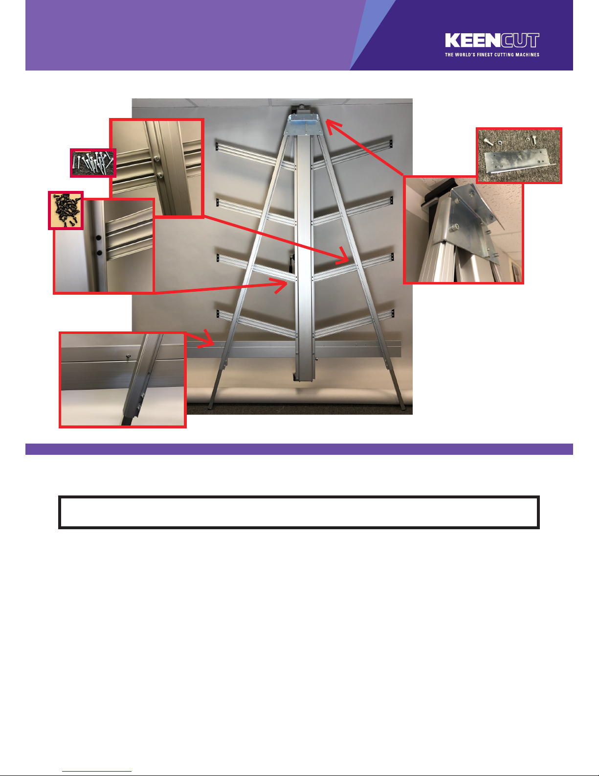
3.4
Assembly
Fitting the support arms & wall mounting bracket
1. Get help to slowly lift the machine and lean it so the front faces towards the wall. Carefully
place a scrap of card or board between the top end of the machine and the wall to prevent
any damage.
NOTE: Ensure the machine is tied or held in position safely whilst the following
steps are carried out.
2. Replace the screw and two washers in the squaring arm using the 3mm hexagon key.
3. Fit the two screws to secure the legs at the top of the main body using the 6mm hexagon key,
tighten both screws fully. Tighten the other two adjacent screws.
4. Fit the support arms:
NOTE: The screws t into special grooves in the underside of the supports. The grooves have
teeth on their sides to match the teeth of the screw thread, the screw can be tted in the groove
anywhere along its length but be careful to make sure the screw is kept perpendicular to the Support
and not screwed in out of line.
Use one of the long screws in each of the holes along the legs of the machine and short
screws to x the support arm to the main body. Ensure the ends of the supports are rmly
against the main body and the screws are aligned with the special grooves as
explained above.
5. If a free standing kit is to be tted to the machine proceed directly to page 3.6.
6. Fit the wall mounting bracket to the top of the main body, fasten the screws nger tight
only.
❷
❸
❻
❹
❹

3.5
Assembly
Attaching machine to wall with mounting bracket
NOTE A: If you are going to t the free standing kit (optional) turn to next page.
NOTE B: Ensure the wall is stable and use the appropriate xings.
1. Stand the machine vertical and turn around so the machine is now facing away from the wall.
2. The wall mounting bracket should lay ush against the wall. Mark the position of the wall
xings with a short pencil.
3. Move the machine away and remove the wall mounting bracket.
4. Attach the bracket to the wall in the marked position with appropriate xings then reposition
and fasten the machine to the bracket.
Proceed to page 4.1.
❶
❷
❹
❸

3.6
Assembly
Fitting the optional free standing kit
1. Attach the bracket to the top of the machine using the nuts and screws (provided with the
main machine).
Extend the telescopic leg to the same length as the front legs less 12cm (5”).
Assistance will be needed for the following stages
2. Get help to stand the machine up and hold it while the free standing leg is xed to the
bracket using the 6mm hexagon wrench.
3. Swing down the stay and attach the xing block to the back of the main body, tighten all
three screw on the stay (using 5mm & 6mm hexagon wrenches).
4. Extend the telescopic leg so the machine stands evenly.
NOTE: The free standing kit is an optional extra and does not come packed with the main
machine.
❶
❷
❸

4.1
Squaring
Checking the machine for squareness
For your machine to produce accurate square cuts the main body needs to be set so that is is 90o
to the squaring arm, for the following procedure you will need a piece of card or mount tboard at
least 60cm x 100cm (2’ x 3’). The larger the board the more accurate you can set the machine.
Place the board on the machine vertically as
shown and apply the clamp ensuring the bottom
edge is in rm contact with the squaring arm.
Select the cutting blade on the lower cutting head
(see section 6). Cut into the top board to produce
a cut approximately 3cm (1”) long. Disengage
the cutter using the cutter release lever. Lower
the cutter and make a similiar cut at the bottom
of the board.
Unclamp and turn the board around (like the
page in a book) and place it back in the machine
so the same edge is still on the squaring arm but
do not clamp it. Align and engage the blade so it
enters the previous made cut at the bottom edge
of the board. Now apply the clamp.
Raise the cutter to the top of the board, if the
machine is square the blade should enter
the same cut as made previuosly. If not refer
to the following page to make the necessary
adjustment.
❶ ❷
❸ ❹

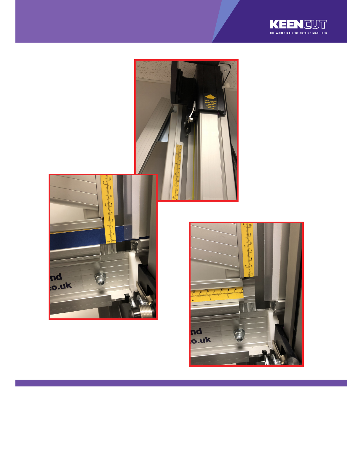
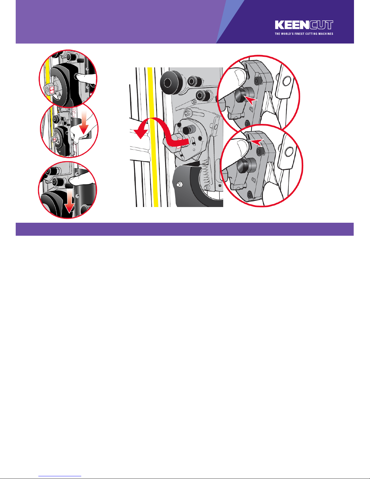
4.2
Squaring
Adjusting the squareness
NOTE: Before making any adjustments carry out the squareness check as desribed in the
previous page.
It is assumed that the board used for the test is still clamped in the machine. From the test results
determine if the last cut made in the top of the board is to the left or right of the previous cut, as
shown above:
1. Slacken the two screws (A) joining the squaring arm to the two legs.
2. Slacken the left hand nut (B) joining the squaring arm to the main body, make sure the right
hand nut (C) is tight.
3. Release the clamp and position the board such that the blade is held in the cut on the bottom
edge of the board. Press down on the board to make sure it is in good contact with the
squaring arm.
4. Turn the squaring adjustment knob (4) on the right hand leg in the direction described next
dependent upon the position of the top two cuts. If the second cut is to the right of the rst cut
turn the adjustment screw clockwise when viewed from underneath. If the second cut is to
the left of the rst cut turn the adjustment screw counter-clockwise when viewed from
underneath. The adjustment screw should be moved so that when the blade is moved to the
top of the board it cuts between two existing cuts, the plastic sightline xed to the edge of
the clamp gives an indication where the machine is going to cut.
5. Repeat the squareness check.
6. Tighten the screws/nut (A, & B).
Ⓐ
ⒶⒷ
❹
Ⓒ
5.1
Calibration
Calibrating the verical scale
1. Trim the bottom of the scale at zero with scissors.
2. Remove the paper backing tape and carefully place the rule adjacent to its groove in the
main body and with the zero end resting inside the material channel of the squaring arm.
When aligned stick the rule in its groove.
3. Again trim the rule at the bottom end as shown.
❷
❷
❸
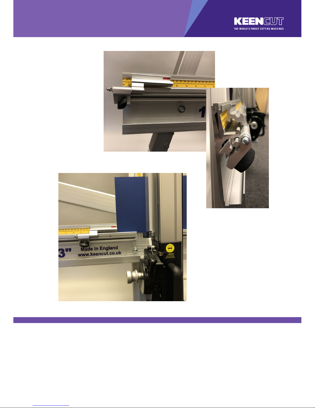
5.2
Calibration
Calibrating the squaring arm scales
The top edge of the squaring arm slides left to right to enable calibration. Use the 3mm hexagon
wrench to loosen the screw in the back of the squaring arm if adjustment is necessary.
1. Slide the production stop onto the outside edge of the squaring arm as shown.
2. Clamp a piece of card in the machine and move the production stop to it.
3. Cut the card and measure, adjust the sliding scale so that the production stop indicates the
measured size.
4. Repeat the process for the other side of the machine.
❶
❷

5.3
Calibration
Fitting the sightline strip
NOTE: The sightline strip is tted to your machine but may wear or get marked with use. A
spare strip is included with the machine, replacement strips are available from your distributor or
Keencut.
The sightline strip is xed to the clamp and then trimmed using the cutting blade to give an accurate
guide when cutting to trim lines, the edge of an image or pencil marks.
NOTE: Do not engage the twin wheel cutter until after reading its instructions for use in section 6.
Engaging the twin wheel cutter interferes with the sightline strip and can cause damage to it. A gap is
left in the sightline strip at a convenient height to enable the twin wheel cutter to be engaged.
1. Remove the worn sightline strip by peeling it o and clean any surplus adhesive with solvent
cleaner on a cloth. Remove the backing paper and starting at the bottom press the strip rmly
in the channel provided working upwards and cut o at a convenient height. Leave a gap of
18cm (7”) and then t the remainder of the strip.
2. Place a piece of rm board up to 6mm (1/4”) thick on the machine to bridge the gap running
down the back of the main body, this needs to be the full height of the clamp.
3. Place a piece of card or foam board 3-6mm (1/8”-1/4”) thick under the full length of the
exible part of the sightline strip, not under the aluminium clamp itself. Depress the
clamp handle so that the sightline strip is pressed at across the surface of the board.
4. Keep ngers clear and using a block or tool hold down the top left corner of the strip to start
the cut. With the turret rachet disengaged (scoring page 6) press the blade lightly on to the
surface of the sightline strip and score along the full length. Repeat and trim the sightline strip
in 2 or 3 cuts.
NOTE: If a board is not available to go the full length of the clamp use two or more pieces or trim
the strip in stages.
❶
❷
❸
❹

6.1
Operation
Using the clamp
The clamping system enables the operator to control the grip pressure by means of an integral
friction brake, that maintains the clamping force at the pressure applied by the operating lever. Soft
materials can be held rmly without sustaining damage and solid materials are held rigidly without
movement. By following the guidelines below it will help you to get the most from the machine.
USE CLAMPING INSTRUCTIONS
Soft materials such as
Foamcore boards, lightweight
card, etc.
Use light to medium pressure. The underside of the clamp grips an
area nearly 4cm (11/2”) wide with a non-marking sponge rubber
and reasonable force can be applied. If in doubt clamp a sample
rst with the good surface facing outwards.
Harder materials such as
PVC foam board, MDF or
composite boards such as
Dibond.
Use medium to heavy pressure.
Cropping to trim lines, pencil
marks, etc. (see drawing).
Place material in approximate position under clamp, apply light
clamp pressure to allow the material to be repositioned. Align the
trim marks with the edge of the sightline strip and clamp.

6.2
Operation
The multi-tool cutter head & counterbalance
The Excalbur 3S is tted with two sliding carriages running on a vertical slideway and each carriage
is tted with a cutting head. The top carriage is tted with a twin wheel cutter for use with rigid boards
such as aluminium composite panels, MDF, hardboards. Refer to ‘Using the twin wheel cutter’ for
more details. The lower or multi-tool cutter head has a rotating turret arrangement where either of
the two cutting tools can be selected:
The cutting blade The scoring blade
1. To select a dierent cutter pull the turret handle out to the left about 6mm (1/4”) and rotate in
either direction, the turret will click into the correct position for the cutter indicated. Please
note that there are three positions on the turret but only two positions are used on this version
of the Excalibur.
2. The indicator label seen in the cutter guard window shows which cutter is active.
3. The counterbalance can be attached to either cutting head for easy, fatigue free working. it
is normally attached to the twin wheel cutter but to attach it to the multi-cutter head, lock the
twin wheel carriage in place using the white plastic thumb screw. Raise the multi-cutter to
engage the counterbalance rocker, press the lower head of the rocker to connect it to
the carriage.
❶
❷
❸
6.3
Operation
Using & changing the cutting blade
Basic cutting technique: Select the cutting blade position on the turret and clamp the material in
the machine.
Move the cutting head beyound the top pf the material to be cut.
1. Press to engage the cutter. Draw the cutter down to the bottom of the machine where it will
disengage automatically.
2. Should you engage the cutter by mistake or for any reason want to disengage the cutter
without moving it to the bottom of the machine pull down the cutter and release lever.
Using the blade support plates: The two support plates either side of the blade are designed to
give maximum rigidity of the blade when cutting hard or dense materials. To adjust the support plates
swing down the cutter guard by undoing the gurad locking knob.
3. Turn the turret ½ turn until blade is pointing towards you and unlock the blade clamping
screw. The support plates can be adjusted by sliding the black pin in the slot. Move the plates
to suit the material.
For cutting most materials the support plates can be set about 12mm (1/2”) from the blade tip.
Changing the cutting blade:
4. Unlock and swing down the cutter guard, rotate the turret so the cutting blade is facing
outwards.
5. Undo the blade clamping screw a number of turns to release the blade.
6. Change or turn over the blade, insert it back into the turret as far as it will go. Tighten the
blade clamping screw, the safety pin will engage to hold the blade in position. At this point
the position of the blade support plates can be adjusted to suit the thickness of material being
cut, further tightening of the screw will clamp the blade in position.
7. Rotate the turret back to the cutting position. Replace the guard ensuring it is locked closed.
❶
❷
❸
❹
❺
❻
6.4
Operation
Cutting thick material using the ratchet latch
Ratchet latch
1. A unique feature of the Excalibur is the ‘ratchet latch’, this enables thick dense materials
such as PVC foam board to be cut easily in stages. Count the number of ‘clicks’ to position
the blade just below the surface of the material to make your rst cut then add an extra ‘click’
for the second and subsequent cuts.
2. Pull down the latch lever to disengage the ratchet if required.
As a rough guide when cutting PVC foam boards:
THICKNESS TAKE
3MM (1/8”) Initial surface cut + 1 additional cut
5MM (1/4”) Initial surface cut + 1 or 2 additional cuts
10MM (3/8”) Initial surface cut + 3 or 4 additional cuts
3. Should you engage the cutter by mistake or for any reason want to disengage the cutter
without moving it to the bottom of the machine pull down the cutter release lever.
4. For some operations (such as scoring acrylic) the ratchet latch needs to be disengaged, so
that nger pressure is used to make the score/cut. This is done by pulling the black knob on
the edge of the spring spool down to face towards the user. To re-engage the ratchet latch
push the small black knob away so it points upwards.
❶
❷

6.5
Operation
Using & changing the scoring blade
The scoring blade is designed to score acylics, Plexiglas and other similiar rigid plastics. Trials
should be carried out on scrap materials rst to ensure you obtain the required standard of cut.
Scoring/breaking technique
Select the scoring blade position on the turret and clamp the material in the machine.
1. Turn the ratchet hold-o knob to disengage the ratchet.
2. Clamp the plastic to be scored in the machine, position and depress the cutting head so the
blade touches the plastic at the top.
3. Apply thumb pressure to the cutter and draw the blade down the material in one continuous
motion.
4. Remove the plastic from the machine and snap it by hand.
CAUTION ALWAYS USE HAND AND EYE PROTECTION WHEN SNAPPING PLASTIC
Changing the scoring blade
Unlock and swing down the cutter guard, rotate the turret so the scoring blade is facing outwards.
4. Release the blade clamping screw.
5. Eject the medium duty utility blade using the black ejector pin, replace the blade to the right of
the clamping plate, push the blade in as far as it will go and tighten the blade clamping screw.
Rotate the turret back to the cutting position. Replace the guard ensuring it is locked closed.
Replacement medium utility blades are available from Keencut or your distributor.
❶ ❷
❸
❹
❺

6.6
Operation
Using & changing the twin wheel cutter
The twin wheel cutter is mounted on the upper cutting head and is used for cutting rigid materials
such as aluminimum composite panel and MDF up to 3mm (1/8”). Many other softer boards and
card can also be cut, trials should be carried out to ensure the desired quality of cut is obtained.
NOTE: The twin wheel cutter must be parked above the top level of the clamp when not in use
otherwise the cutter will interfere with the sightline strip if the clamp is operated.
1. Position the material in the machine and apply the clamp.
2. Bring the twin wheel cutter down until it makes contact with the sheet edge and stop. Take a
rm grip and then push the cutter down through the material without stopping.
The cutting wheels generally last more than a year with average use but this is dependant upon daily
use and the material being cut. The signs the wheels are wearing out are:
• A rough nish predominantly on the right hand side of the cut, with aking on material such as
MDF.
• The bottom of the cut bursting out rather than being cut neatly.
• The board trying to turn under the clamp when being cut (also check the clamp pressure).
Changing the twin wheel cutter
Lock the cutting head at a convenient height using the white nylon locking screw.
3. Hold the twin wheel cutter and its guard to prevent them from falling and remove the screw
with a 6mm hexagon wrench.
4. Slide the cutter towards the top of the main body and lift out.
Replacement wheels or cutters are available from Keencut or your distributor.
❷
❹
❺

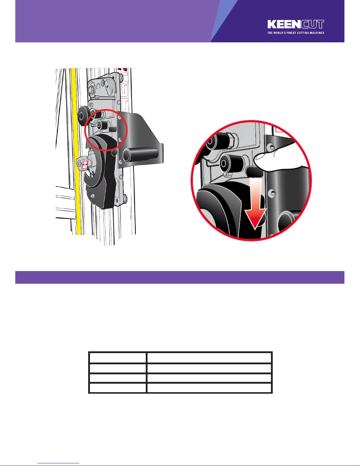
7.1
General maintenance
Cleaning
Keencut machines are designed to be virtually maintenance free, however we do recommend
regular cleaning. Do not wipe the squaring arm channels or remove any debris with ngers, as it
may contain sharp particles such as glass. Use a vacuum cleaner if possible or if a soft brush is
used, work slowly and do not allow particles to ick o the bristles.
Lubrication
The slideway can be cleaned and lubricated occasionally using a silicone lubricant. Removing any
excess with a cloth. The multi cutter assembly may require dusting out periodically do not lubricate
or adjust without seeking further advice from your distributor or Keencut.
Except glass cutting oil on the glass cutting wheel only
Adjusting the sliding bearings
1. Attach the balance weight (see page 6.2) to the other cutting head, hold the cutter at waist
height and place a 2mm hexagon wrench on the top adjustment screw. Move the cutting
head up and down and tighten the scew very gradually until the cutting head dows not
fall under its own weight. Loosen the screw by the smallest amount you can until it does fall
under its own weight. Repeat the process with the other three adjustment screws A.
Adjusting the clamp pressure
2. The pressure of the clamp is in relation to the amount of pressure applied to the operating
handle. However in time the maximum clamping pressure can reduce due to wear on the
friction black (hidden within the machine), compensation for this can be made by adjusting the
two small grub screws B in the operating handle housing as shown. Turning the screws
clockwise will increase the maximum clamping pressure.
3. Turn both screws all the way in and then undo by a quarter of a turn, slight adjustment can be
made to ne tune the pressure. Do not operate the clamp with the adjustment screws tight.
DO NOT USE OIL ON ANY PART OF THE MACHINE
❶
Ⓐ
Ⓐ
Ⓐ
Ⓐ
❷
Ⓑ
 Loading...