

Page 1
Evolution E2
Inspired Design – Precision Engineering
USER INSTRUCTIONS
Thank you for choosing the Keencut Evolution E2. Every effort
has been made to bring you a precision engineered product
with the promise of many years of valuable service. In order to
obtain maximum benefit from your machine please read these
instructions carefully. For advice and assistance or replacement
parts please contact your distributor or Keencut.
Keencut Limited, Baird Road, Willowbr
ook Industrial Estate, Corby
, Northants, ENGLAND NN17 5ZA.
Telephone: 01536 263158 Fax: 01536 204227 E-mail: [email protected]
www.keencut.co.uk
KC-EDITION 7168-01/12
Page 2

1 Contents
2 Before Set Up
2.1 Installation Recommendations
2.2 Check and Adjust Worktop Flatness
The Fixing Bracket Jacking Screws
2.3 Position the Fixing Brackets
3 Set Up
3.1 Fit the Lift Handles (remove strapping)
3.2 Adjust for Alignment
3.3 Position the Base Fixing Brackets
3.4 Check and Adjust the Clamping
3.5 Adjust for Flatness and Grip - paper test
3.6 Build up Bench Surface
4 Operation
4.1 About the Blades - inserting and setting the blade - blade
depth adjustment
4.2 Blades and Blade Holders
4.3 Changing the Blade Holder
4.4 Inserting the Graphik Blade
4.5 Changing the Depth
4.6 The Rotary Cutter (Textile cutting Attachment)
4.7 Using The Rotary Cutter
4.8 Changing The Rotary Blade
4.9 Medium Duty Blade Holder
5 Maintenance
5.1 Cleaning and Lubrication - (warning note)
Adjusting the Cutting Head Sliding Bearings.
1
Contents
1
Page 3
2.1 Before Set Up 2.1
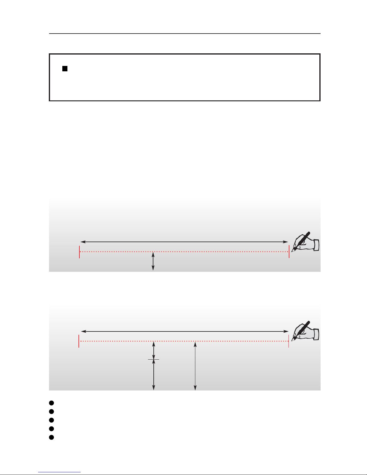
Overall length of cutter
Worktop
9.5cm
Overall length of cutter
Worktop
15cm
24.5cm
9.5cm
Evolution E2 160cm (64”) overall length 193cm (74”) 4 base fixing brackets
Evolution E2 210cm (84”) overall length 243cm (94”) 5 base fixing brackets
Evolution E2 260cm (104”) overall length 293cm (114”) 6 base fixing brackets
Evolution E2 310cm (124”) overall length 343cm (133”) 7 base fixing brackets
Evolution E2 360cm (144”) overall length 393cm (153”) 8 base fixing brackets
CHECKING THE BENCH FOR INSTALLATION
Please note! As part of the installation there are a number of checks and
adjustments to be made and it is important to perform them correctly to ensure
consistent top quality performance for the life of the machine.
The Evolution E2 Cutter Bar can be fixed to a KEENCUT Proteus bench or to an existing
work bench. The bench should be rigid with a flat worktop (within 3mm (1/8") overall)
and made from MDF or similar material to accept fixing screws.
To enable the flip-over storage function to operate the Evolution E2 must be fitted close
to the edge of the bench but if it is required nearer the centre of the bench do remember
that cutting tough materials will be more difficult if the operator needs to stretch too far
to reach the cutter head.
If the cutter is to be mounted along the edge of the bench draw a line 9.5cm in from the
edge of the worktop and the length of the cutter as listed below.
Should you want to use the cutter, for example 15cm in from the edge, draw the line
15 + 9.5 = 24.5cm from the edge of the worktop.
Page 4
2.2 Before Set Up 2.2
CHECK & ADJUST THE WORKTOP FLATNESS
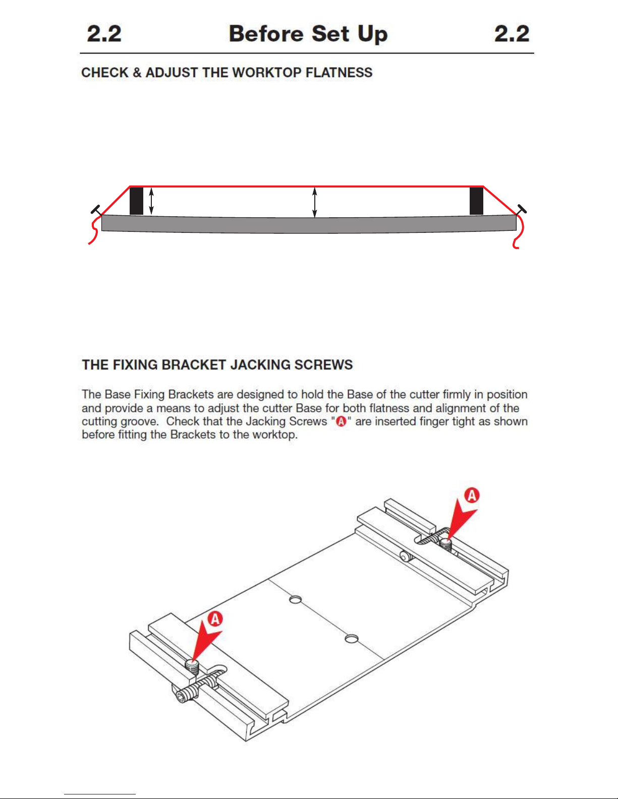
Check the flatness of the worktop by stretching a thin piece of strong thread between
two blocks (of the same height) approximately over the line. Measure the highest and
lowest part of the worktop under the thread, the difference between the two measurements should be no more than 3mm (1/8"). If it is greater it will be necessary to adjust
the surface flatness with a new top or by using spacing pieces under each bracket.
?mm
?±3mm
¸
worktop
§
§
Adjust the surface flatness by adding packing pieces made from 1.5mm - 3mm (1/16" 1/8") thick rigid material such as PVC Foamboard, under the Base Mounting Brackets as
they are installed (next section).
THE FIXING BRACKET JACKING SCREWS
The Base Fixing Brackets are designed to hold the Base of the cutter firmly in position
and provide a means to adjust the cutter Base for both flatness and alignment of the
cutting groove. Check that the Jacking Screws "
A " are inserted finger tight as shown
before fitting the Brackets to the worktop.
A
A
Page 5
➤
➤
18cm (7")
43.5cm (17
1
/
8
")
2.3 Before Set Up 2.3
SET OUT THE FIXING BRACKETS
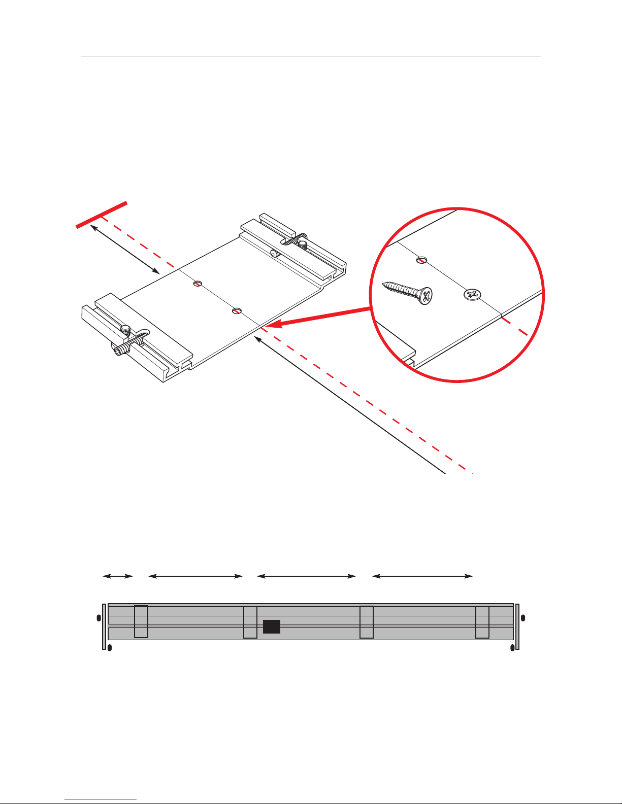
Place a Bracket 18cm (7") from the end of the pencil line as shown, ensuring that the
groove in the centre of the Bracket is aligned with the pencil line and fix to the worktop
using two short screws "
D" provided. Fix the remaining brackets accurately along the
line leaving a 43.5cm (17
1
/8") gap between each one. Check that the brackets are all
aligned correctly and if not remove the incorrectly positioned bracket and replace slightly
to one side of the original position to create new screw holes.
43.5cm (17
1
/8") 43.5cm (171/8")43.5cm (171/8")
18cm
(7")
● Example:
Evolution 160, 4 base fixing brackets
1234
Evolution E2 160cm (64”)
D x 2
Page 6
2.4 Before Set Up 2.4
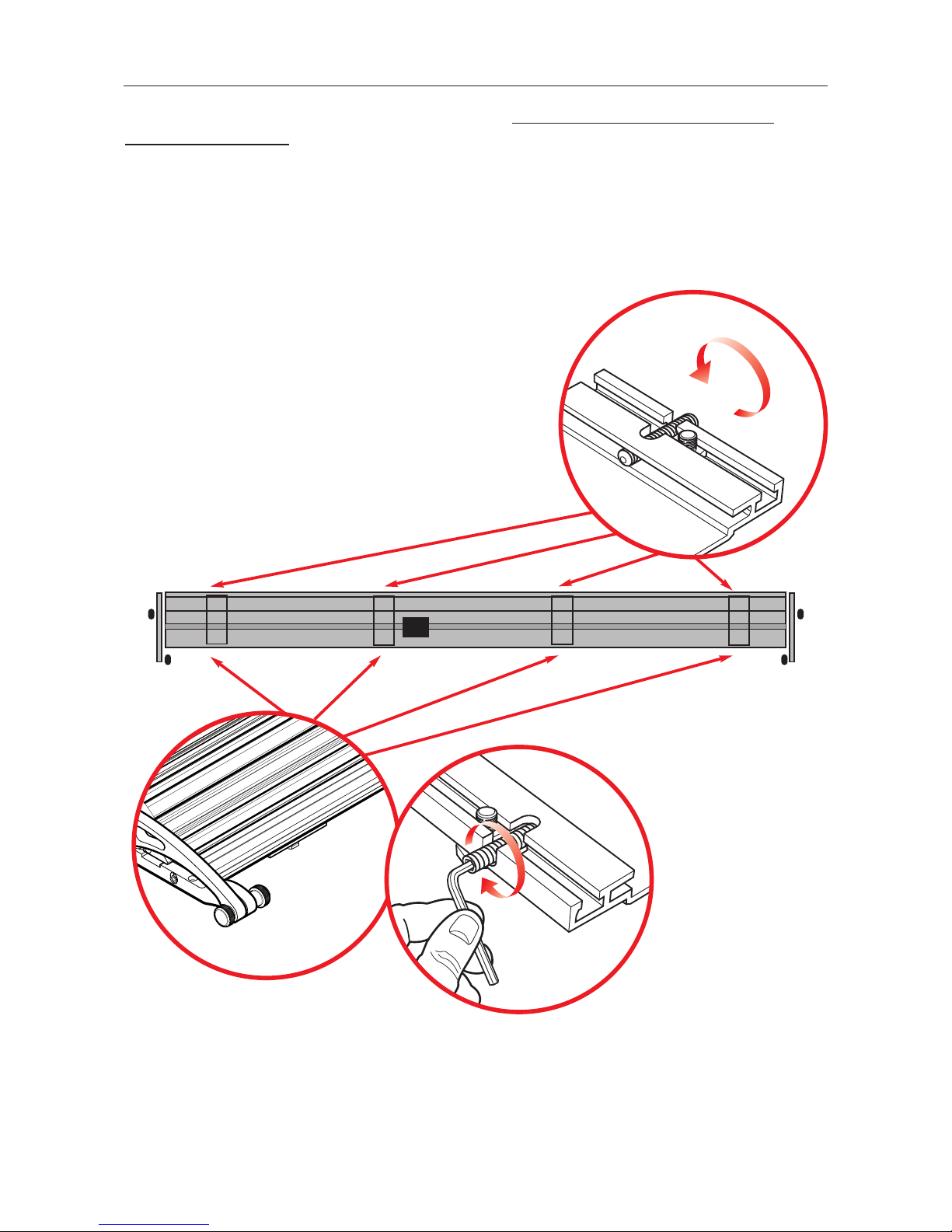
Lift the Evolution E2 cutter bar from its crate but do not remove the clear plastic
stretch-wrap bands holding the base to the cutter bar. Place the Evolution E2 centrally
on the Brackets and manoeuvre it until the base is located properly down on each of
the Brackets.
Tighten the grub screws "
B" at the back of each of the Brackets by 4 full turns and then
tighten the front grub screws "
A" fully (approx 4- 6 turns). Remove the clear plastic
stretch-wrap bands.
➤
➤
➤
B
A
Page 7
3.1 Set Up 3.1
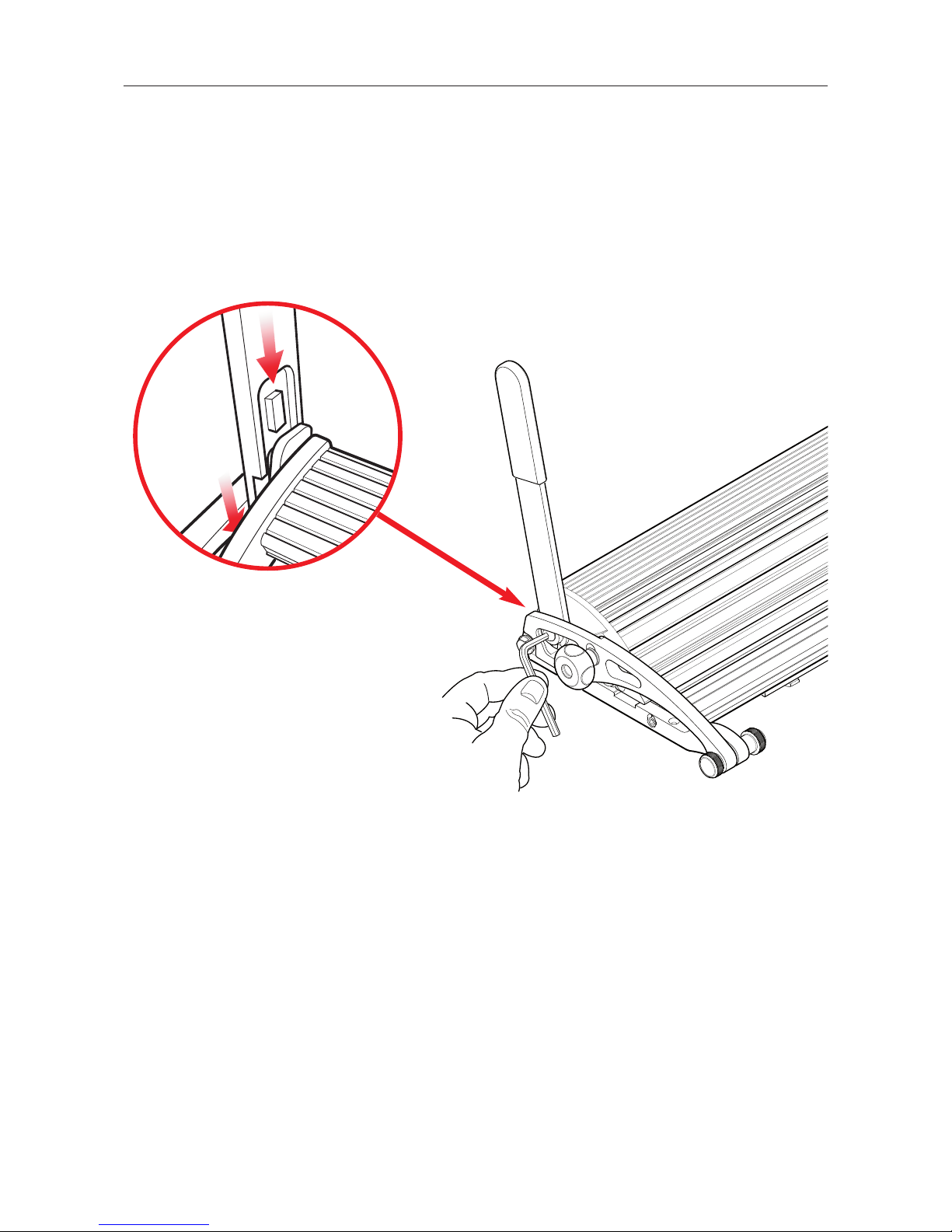
FIT THE LIFTING HANDLES
Fit the Lift & Hold Handles at each end of the cutter bar. Position the machined section
of the handle towards the centre of the Evolution E2 and insert it into place at the angle
shown (Fig 1). Once in position straighten so that the rectangular feature on the handle
fits into its mating hole in the adjacent black steel component attached to the machine.
Fully tighten the fixing screw (Fig 2) using the 5mm Allen key provided.
1
2
CHECK & ADJUST THE CUTTING GROOVE ALIGNMENT
The Evolution E2 cutter bar has been adjusted to a straightness of 1:15000 along its full
length using a laser beam controlled instrument. It is desirable to adjust the cutting
groove in the aluminium base to match the straightness of the cutter bar and the base
brackets provide the means to do so.
The back of the cutting groove in the Evolution E2 Base should be in line with the edge
of the cutter bar to allow the blade in the cutting head to run the full length of the
machine without touching either side of the groove, if it does not....
Page 8
B
A
B
A
B
A
B
A
3.2 Set Up 3.2
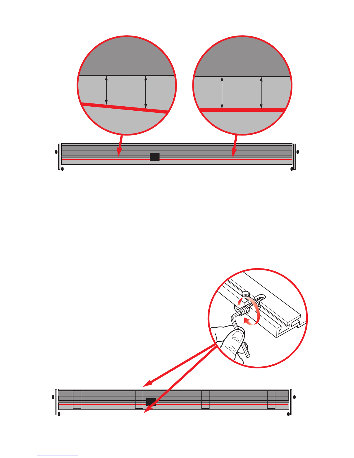
Adjust the straightness of the Base by adjusting the front "A" and rear "B" grub
screws in the Base Fixing Brackets:
To move the cutting groove towards "
Y" loosen the rear grub screw "B" in the nearest
Brackets and tighten the front grub screw "
A" until the groove is aligned with the cutter
bar. Tighten the rear grub screw "
B" until it meets resistance and the Base is held firmly.
Using a Lift handle raise the cutter bar and lower it again to the Base surface and check
the alignment. Adjust the cutting groove finally if required.
To move the cutting groove towards "
X" loosen screw "B" first and
reverse the sequence above.
If there is insufficient Base adjustment using the "
A" and
"
B" screws it is likely that one or more of the Brackets
will need to be removed and realigned on
the bench top.
BACK
FRONT
? = ?
? < ?
✓
✗
Y
Y
Y
X
X
Page 9
3.3 Set Up 3.3
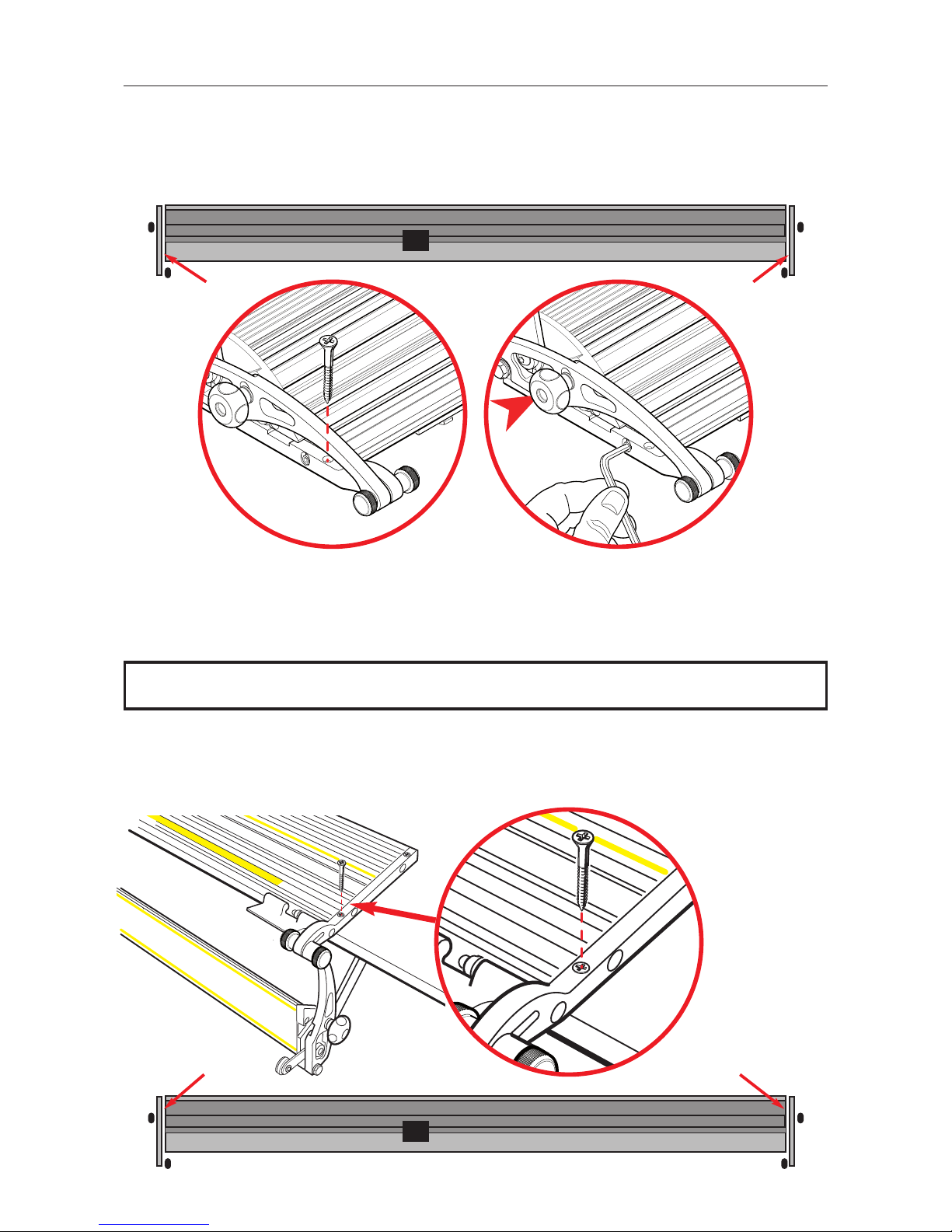
Place two of the long wood screws "A" in the front holes of the Fixed Arms and partially
insert them into the bench surface but do not tighten. Loosen, by one full turn anti-
clockwise, the four hexagon socket screws "
B" joining the Fixed Arms to the Base.
Fully insert the two wood screws "
A".
To enable the table surface to be cleared of the cutter bar when it is required for other
work the whole cutter bar can be lifted and rotated on its hinges towards you so that it
hangs down along the edge of the work bench (this also helps with cleaning).
A
C
A
B
B
B
B
C
A
B
x4
x2
NOTE: Be particularly careful with the longer versions of cutter as they are very heavy.
Carefully swing the cutter bar down and place the remaining two long wood screws "C"
into the back two holes of the Fixed Arms and tighten. Return the cutter bar to its
working position. Tighten all four Allen screws "
B".
C
x2
Page 10
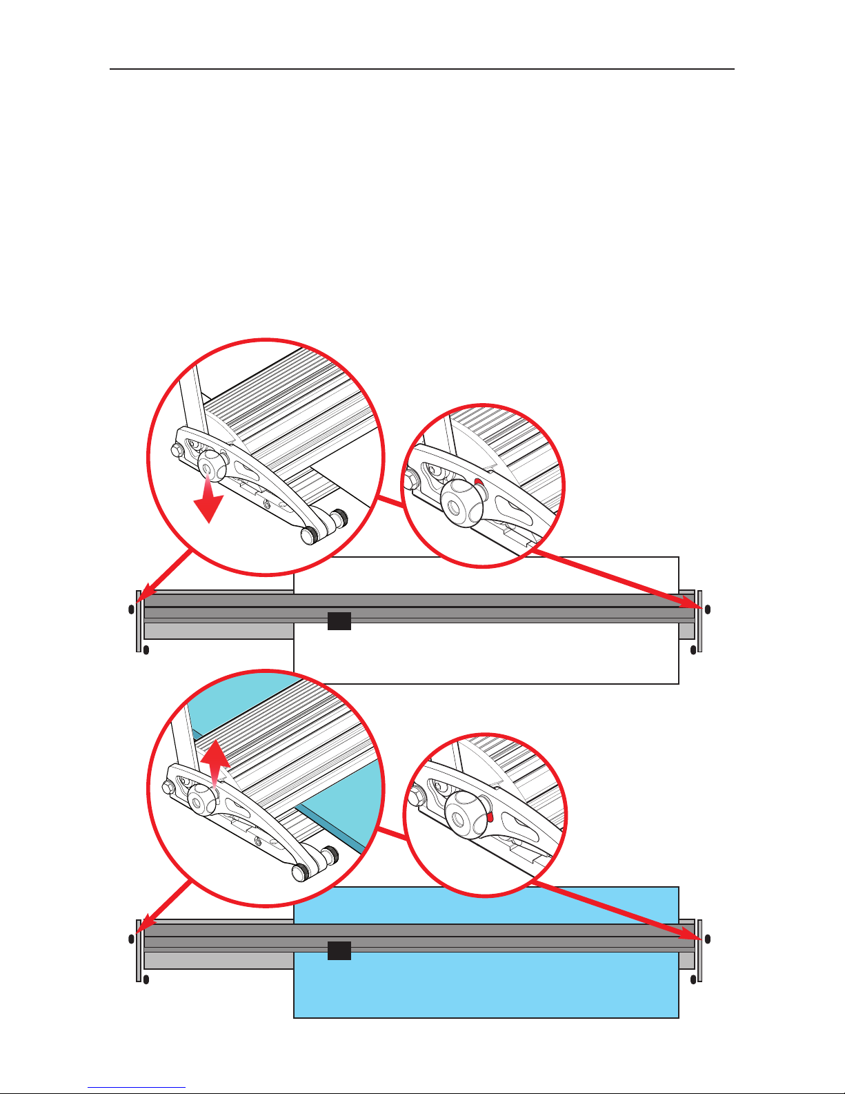
3.4 Set Up 3.4
THIN
THICK
➤
➤
It is essential that the material being cut, whether a thin paper/film or a thick board, is
held securely in the machine during cutting. There is a silicon cord set into the Evolution
E2 Base to grip the underside of the material and two similar grip cords set into the
underside of the Cutter Bar. These should be periodically checked for good condition
and replacements obtained from your Keencut distributor.
There is an integral Levelling Adjustment that enables the full width of the cutter bar to
lay flat on any thickness of material. Place the chosen material under the cutter bar and
release both thumbscrews "
S" the cutter bar will settle to the surface of the new
material. Raise the cutter bar using the lift handle and lower again to ensure correct
alignment and tighten both thumbscrews "
S".
Set the Levelling adjustment knobs to suit paper.
S
S
Page 11
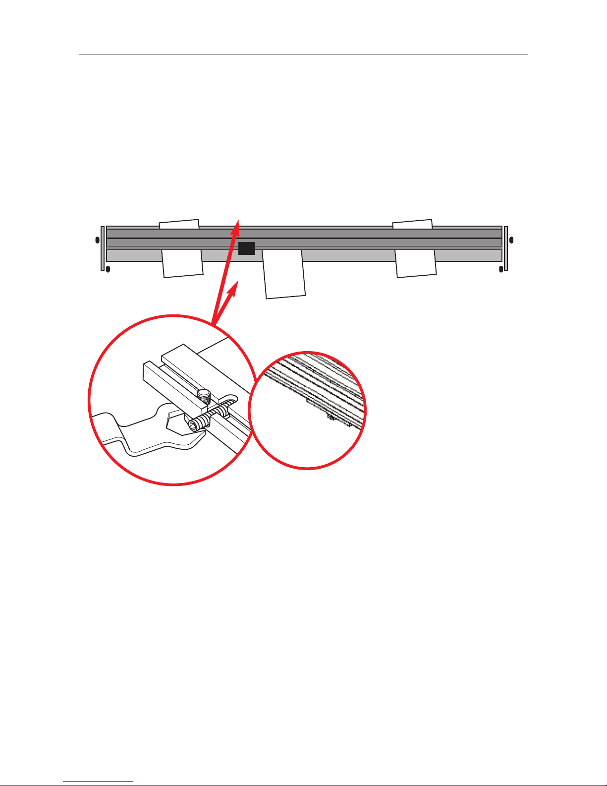
3.5 Set Up 3.5
CHECK AND ADJUST FOR FLATNESS AND GRIP
Check the grip of the cutter bar using a sheet of office copy paper. Starting at one end,
lift the cutter bar and place the paper under it, when lowered, the weight of the cutter
bar should grip the paper. Try to pull the paper free, if it is not clamped sufficiently note
its position and work your way down the cutter repeating the test with the paper and
noting where it is not clamped sufficiently.
EEEE
DDDD
➠
➠
➠
✓✓
Adjust the clamping by turning the Jacking Screws "D" & "E" in the Base Fixing
Brackets that are adjacent to the areas that are not clamping the paper. Turn the
Jacking Screws clockwise (as you look down on them) using the wrench supplied, turn
both the front and rear Jacking Screw by the same amount (to keep the Bracket level)
until the paper is gripped. You may find that two or three adjacent Brackets need
adjusting if you have a wide area that does not clamp.
➤
✗
D
➤
E
Page 12
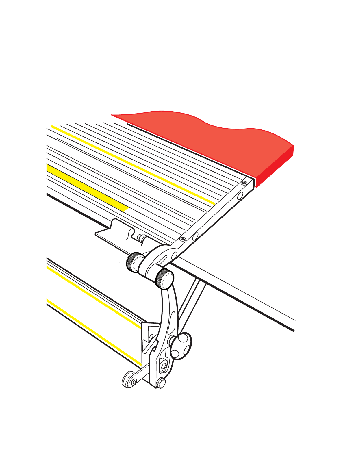
3.6 Set Up 3.6
➤
BUILD UP BENCH SURFACE
Once the Evolution E2 has been installed all that remains is to raise the level of the
remaining surface of the bench by 15 - 16 mm (5/8") The best way is to add a new top
made of MDF or similar solid material. To fix the new top use a thick sealant type
adhesive in preference to screws, as screws may distort the bench top and disturb the
Evolution E2 Base installation adjustments.
Page 13
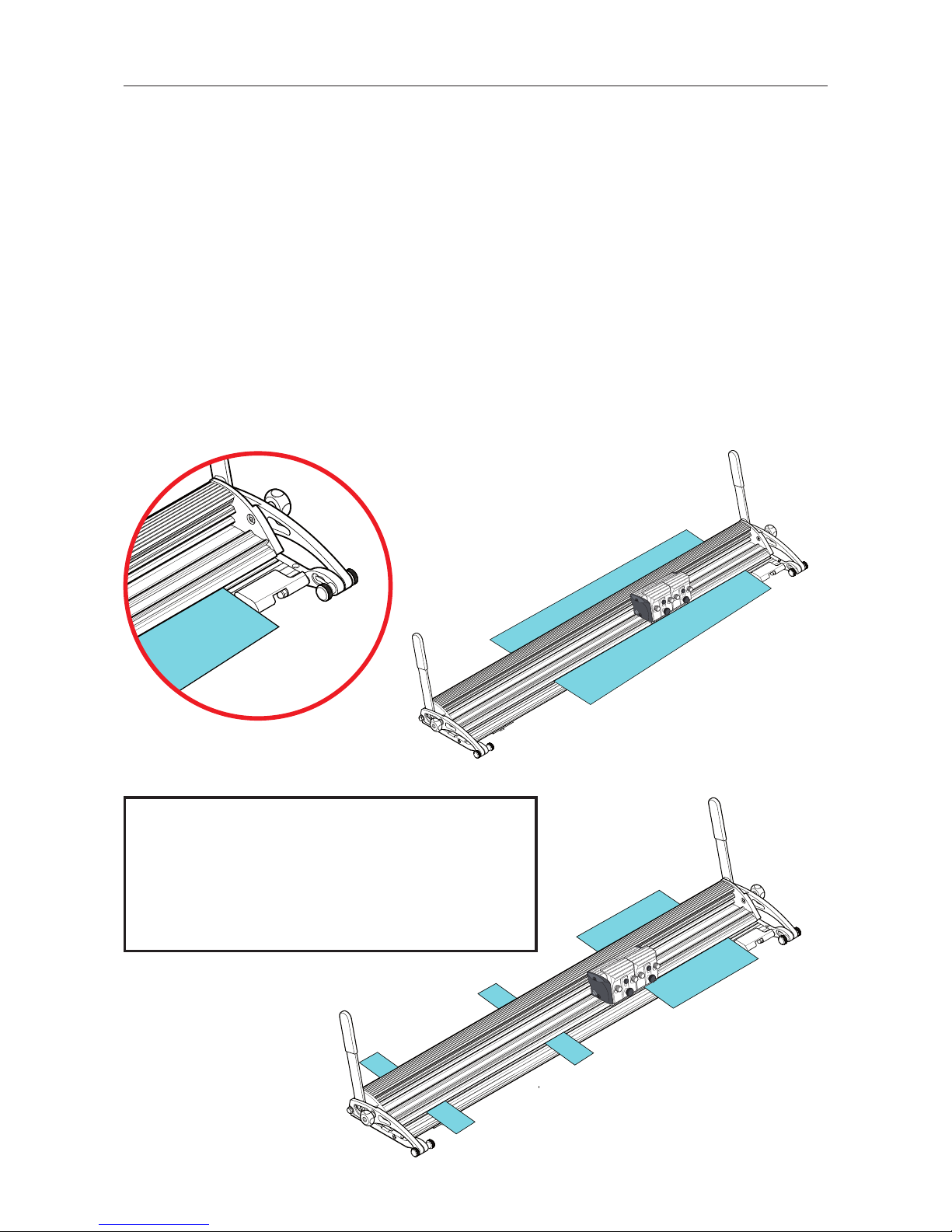
4.1 Operation 4.1
INSERT AND ALIGN THE MATERIAL
Use one of the two Lift Handles to raise the Cutter Bar. With the cutter bar raised place
the material to be cut on the Base. Lower the Cutter Bar by pushing the Lift Handle
towards the cutting edge of the machine. To align the edge of the cutter bar with your
cutting marks slightly raising the Cutter Bar, using the Lift Handle, and adjust the position of the board at each end. The blade will cut within 0.5 to 1mm [0.02" to 0.04"] of
the sight edge; this small gap allows easier alignment when cutting to the edge of an
image.
Check that the width of the Cutter Bar is laying flat on the surface of the material, if not
loosen both Tilt Adjustment Knobs "
G" & "F" then lift the Cutter Bar and lower it down
again to settle it in position and tighten both "
G" & "F". The cutter is now set for cut-
ting all types of material of that thickness.
The flip over Material Stop "
H" is provided to prevent tough materials such as PVC
Foamboard from moving during cutting.
➤
➤
NOTE: If you are cutting a small piece of
board place it at right hand end of the Cutter Bar
against the Material Stop and place scraps of the
same thickness material under the remaining
bar to support it and prevent sagging.
G
➤
F
H
G
Page 14
4.2 Operation 4.2
BLADES AND BLADE HOLDERS
The Evolution E2 is fitted with an all-new vertical action cutting head which reliably
controls the blade depth and eliminates the need for heavy downward hand pressure
when cutting tough materials such as PVC foamboard. Providing a smooth consistent
cutting action on just about every flexible material used in the Graphics and Sign
making Industries.
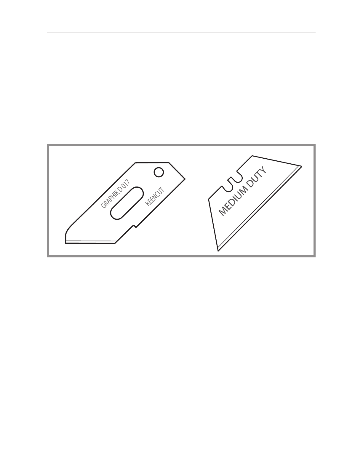
The Sabre Cutter bar has been designed to cut a variety of boards to a
thickness of 10mm (3/8") using standard Medium Duty utility blade. Materials to 13mm
(1/2”) can be cut using the GRAPHIK D 017 blade holder.
Consideration should be given to the toughness of the board being cut and the
maximum depth of cut. It is recommended that heavy materials such as PVC foamboard
should ideally be cut using the Graphik blade holder and to a maximum of 6mm (0.25")
whereas, lighter materials like foam centred board can be cut up to the maximum cutting
depth of the blade being used.
Page 15
4.3 Operation 4.3
CHANGING THE BLADE HOLDER
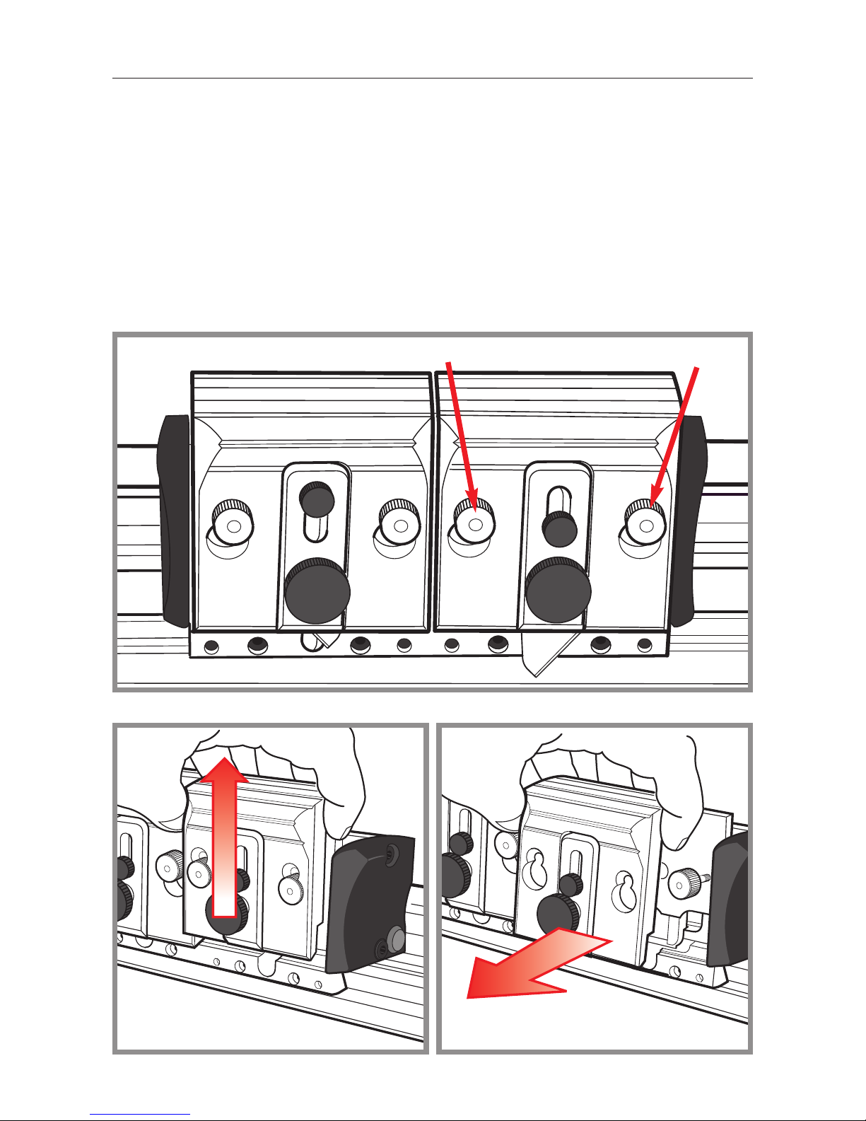
Before removing a blade holder make sure the blade has been removed or guarded
(dependent upon type).
Loosen both of the small knurled knobs
A
by about two turns, raise the blade holder to
align the knobs with holes in the blade holder then pull towards you to release. Reverse
the procedure to attach a blade holder to the cutting head.
The Rotary blade holder has a special safety device to ensure the blade is guarded
before the holder can be removed, this is covered in the Rotary Cutter section.
A
A
Page 16
4.4 Operation 4.4
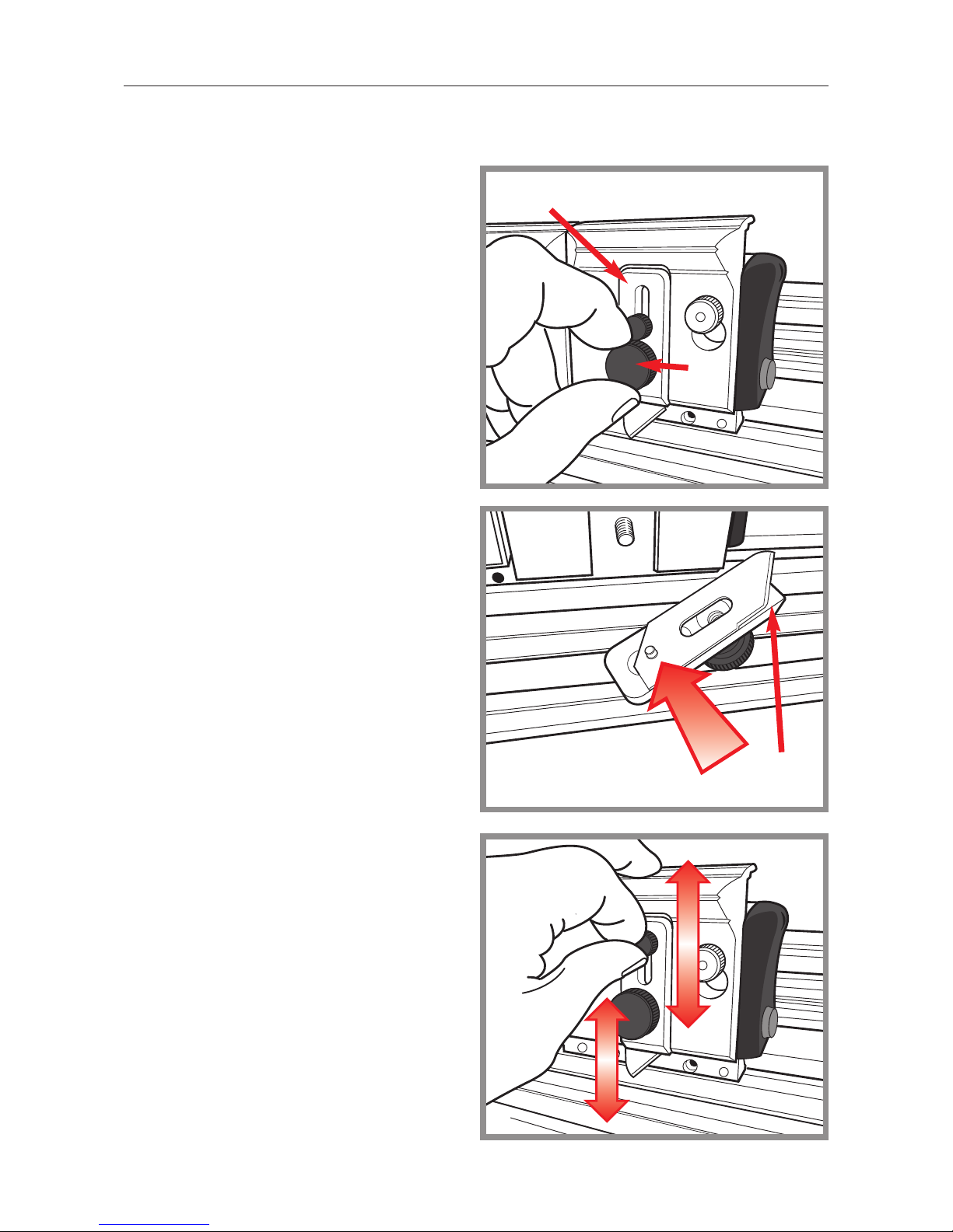
Remove the blade clamping plate B by
undoing the large black clamping screw
C
, if there is a blade already in the
holder it will come away with the
magnetic clamping plate
B
. You will
notice the blade depth adjuster with the
small black knob is free to slide along its
slot and the raised pip on its underside
locates in the small hole in the
GRAPHIK blade.
Ensure there is no debris on the underside of the clamping plate particularly
around the magnet before fitting the new
blade. The blade can be positioned on
the clamping plate either way round
enabling the blade to cut either left to
right or right to left .
Hold the clamping plate in place on the
blade holder and tighten the clamping
knob ensuring the blade is properly
located in its groove.
Before tightening the clamping screw the
blade depth can be adjusted by sliding
the adjustment knob up or down to
retract or extend the blade. It is good
practice to set the depth so that the minimum amount of blade is exposed to just
cut through the material, it takes much
less effort and produces a better cut.
B
C
B
INSERTING THE GRAPHIK BLADE AND SETTING THE DEPTH
Page 17
4.5 Operation 4.5
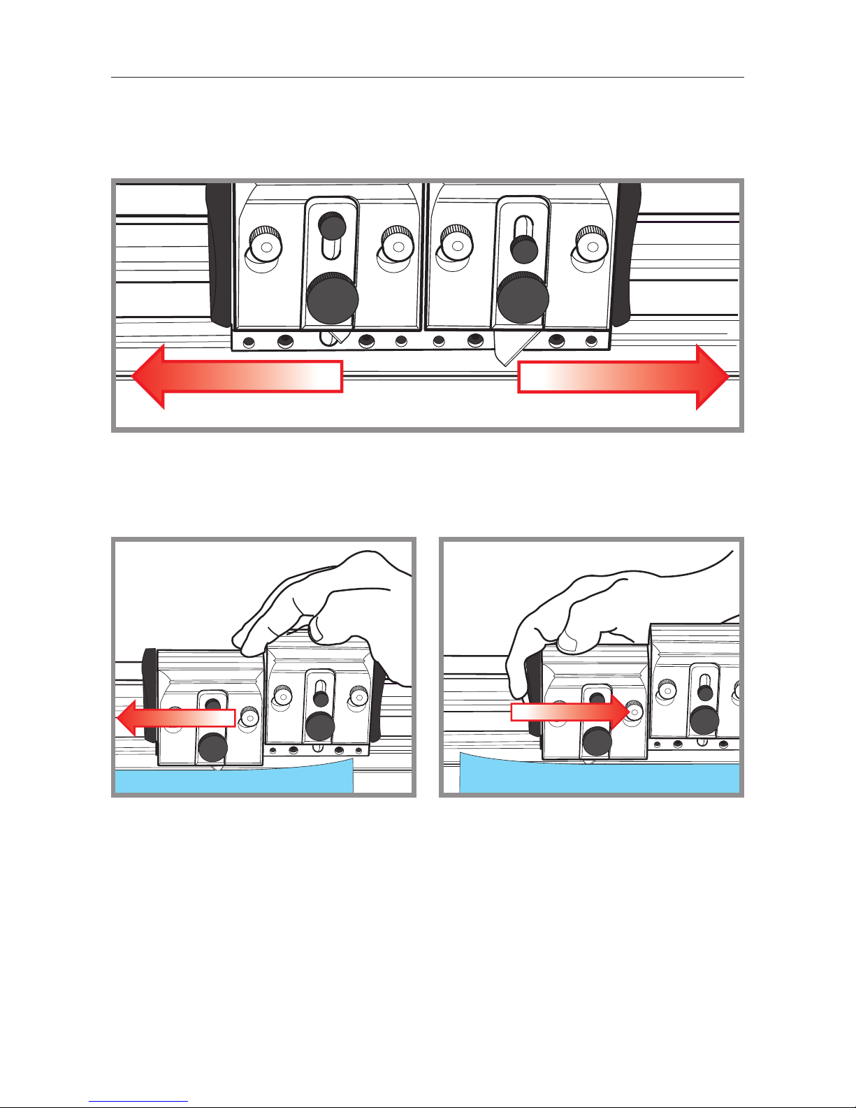
The VA (vertical action) cutting head holds two cutters which can be changed and used
independently of each other. Each of the standard GRAPHIK blade holders can be set
to cut at different depths and in either direction by simply adjusting or flipping the blade
over in the holder. You can also push or pull the cutting head to suit your own comfort.
Once your blade is set move the cutting head near to the start of the cut, press down
the blade holder and push or pull to take the cut. Only light finger pressure is usually
required to depress the blade holder so most of your effort can be directed into pushing
the blade through the material.
SHALLOW CUT DEEP CUT
SCORING HARD PLASTICS
Many hard plastics such as Acrylic can be scored and snapped by hand or over the
edge of a bench (use hand and eye protection). The back edge of the GRAPHIK blade
can be used as a scoring blade, position the plastic sheet in the cutter and draw the
blade backwards across the surface applying downward pressure to the blade holder,
some plastics will benefit from being scored a number of times before snapping.
CUTTING PVC FOAMBOARDS
PVC is a very tough and durable material, to obtain a straight and smooth edge cut the
material slowly, if you cut too fast the board will rip and give a jagged uneven edge.
Considerably higher cutting performance is obtained from warm room temperature
boards, if you store your boards in an unheated room in winter you will find them much
more difficult to cut and the colder the board the slower they will need to be cut.
Page 18
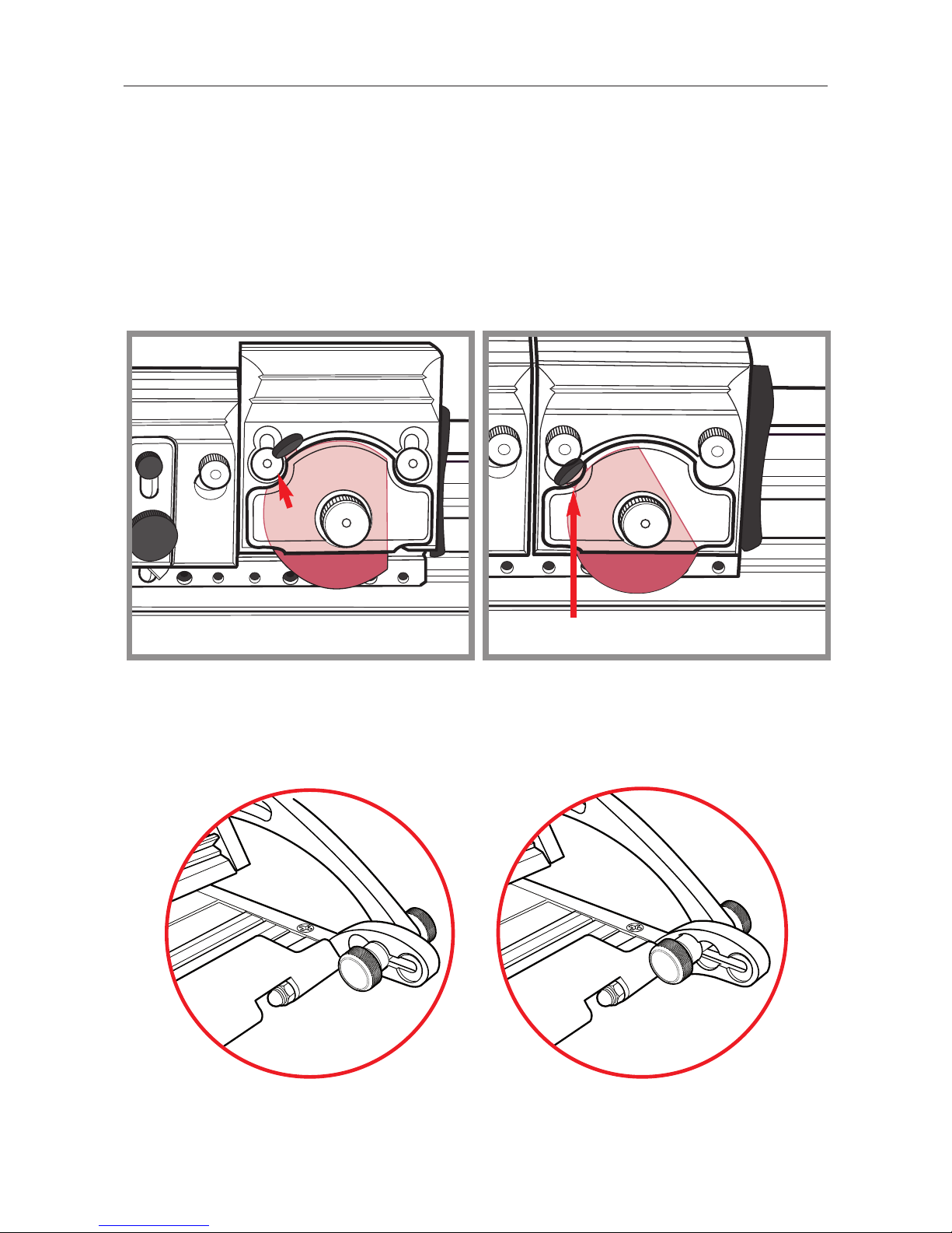
4.6 Operation 4.6
THE ROTARY CUTTER
The Rotary Blade Holder supplied with the machine is used to cut textiles, thin papers
and other flimsy materials, it uses a circular blade to press down onto the surface of the
textile which is held over a plastic strip embedded in the base of the machine.
The red plastic blade guard protects the blade and makes it safe to handle, however, be
very careful as the blade is very sharp. The guard has to be closed to allow the blade
holder to be fitted or removed, align the scallop
D
in the red plastic guard with the left
hand release hole and fit/remove the blade holder in the normal way.
First raise the Cutter Bar using either Lift & Hold Lever, then loosen both of the Hinge
location screws until the underside of the screw clears its location recess. Push the
Cutter Bar until the underside of the location screw is positioned over the middle recess
and tighten Hinge location screws. Repeat at the other end. The Cutter Bar is now
positioned over the plastic Cutting Strip.
The third (furthest) position is also for cutting textile but uses a different part of the
Cutting Strip should it become worn. The Cutting Strip can also be removed, turned
around or flipped over to allow eight tracks to be used before the strip requires
replacement. Replacement Cutting Strips are available from your Keencut agent.
➤
➤
D
GUARD FULLY CLOSED
Page 19
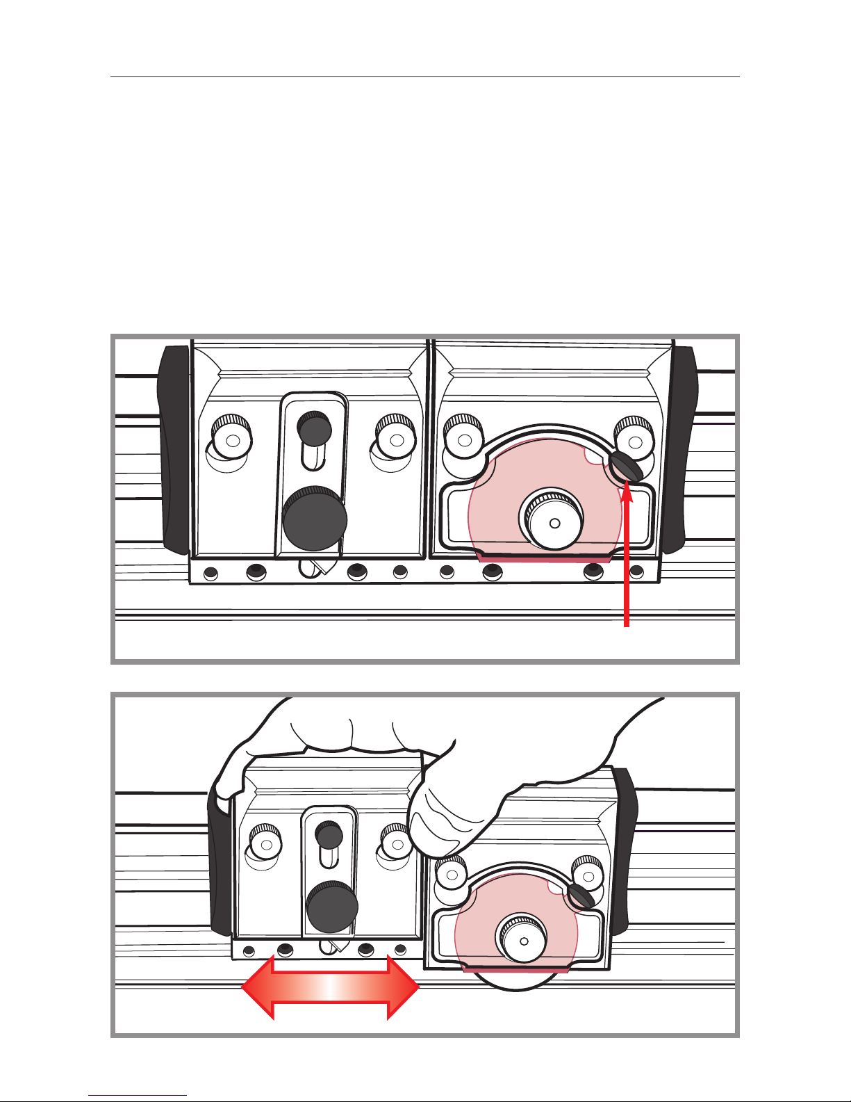
4.7 Operation 4.7
USING THE ROTARY BLADE CUTTER
Position the material to be cut on the machine and lower the cutter bar. Rotate the safety guard grip clockwise to reveal the blade. Apply downward pressure to the blade
holder whilst drawing the cutting blade along the material in one continuous motion.
Some materials will cut better if a harder plastic base is used in place of the plastic strip
embedded in the machine. Acrylic works well for this, use a piece at least 15cm (6")
wide and long enough to support the full cut length of the material, place it under the
cutter bar and the material on top, set the tilt adjustment knobs if necessary and cut in
the normal way. Lighter downward pressure will be required with harder plastic bases.
GUARD FULLY OPEN
Page 20
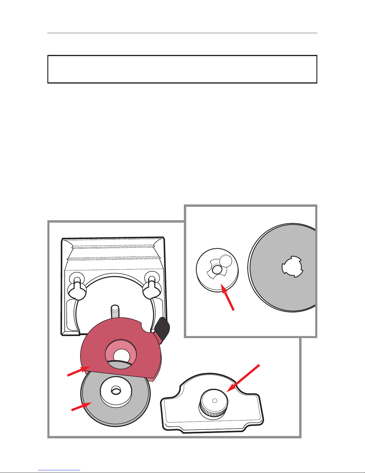
4.8 Operation 4.8
■ The circular blades are extremely sharp - wear protective gloves
and handle with care.
F
E
G
H
CHANGING THE ROTARY BLADE
Unscrew the clamping knob H to release the clamp plate then carefully remove the
blade with the red guard and the blade centre boss.
Separate the blade
E
from the red guard F and push out the magnetic centre boss G,
be extremely careful, the point of a pencil can be used to help push the boss free of the
blade. Ensure there is no debris attached to the magnetic boss or any of the other
components, reverse the procedure to install the new blade.
Upon first use check the blade is revolving, if it is not it is an indication that the clamping
knob
H
is too tight or there is debris inside.
Page 21
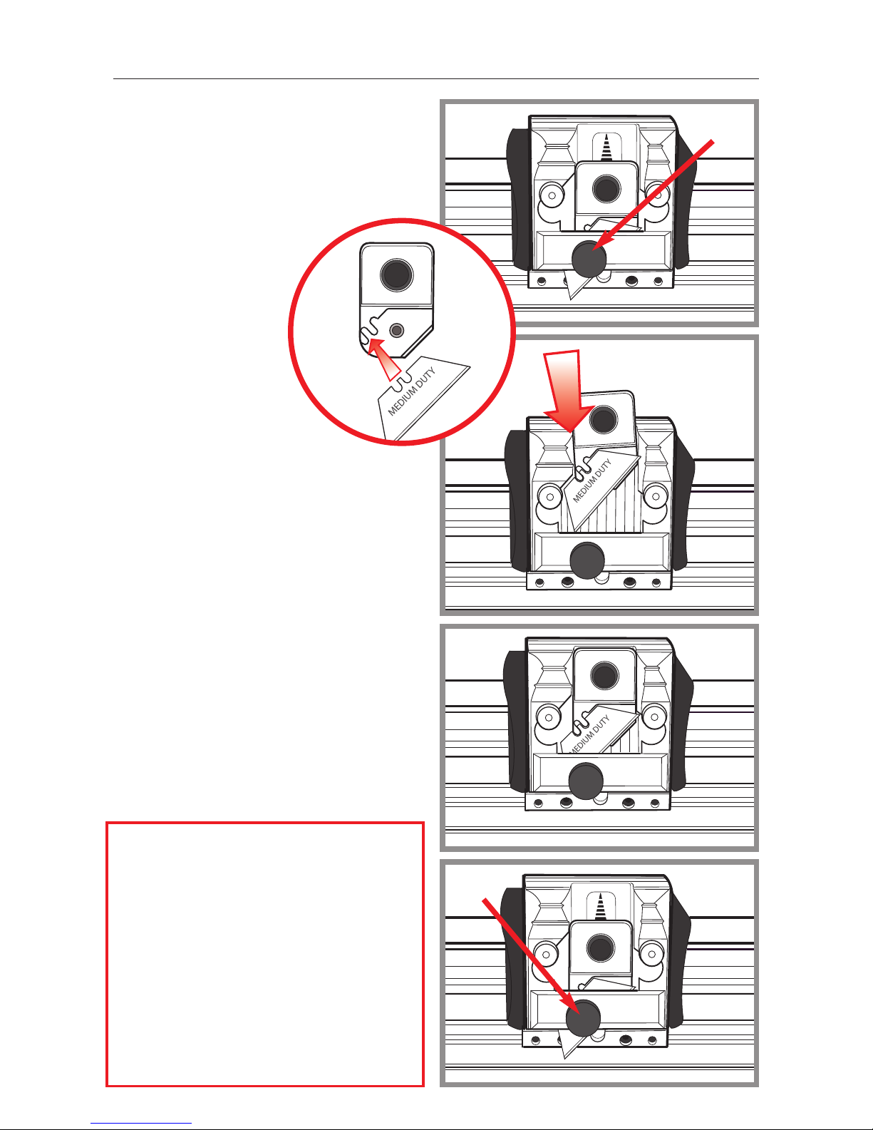
4.9 Operation 4.9
MEDIUM DUTY BLADE HOLDER
Fitting the blade.
Remove the magnetic blade guide by
releasing the blade clamping knob I.
Place blade onto the guide
ensuring the blade notches
are properly located and
the back face of the
blade is lying flat on
the guide.
Lower the blade guide into position
feeding the blade behind the clamping
bar.
Adjust the height of the blade guide to
give the correct blade depth and tighten
the blade clamping screw I.
I
I
Optimum performance is achieved
with a sharp blade set so it is only just
deep enough to cut through
the material.
For cutting tougher materials such as
PVC foamboard and materials up to
13mm (1/2”) thick the ‘Graphik’ blade
holder is recommended.
Page 22
5.1 Maintenance 5.1
CLEANING AND LUBRICATION
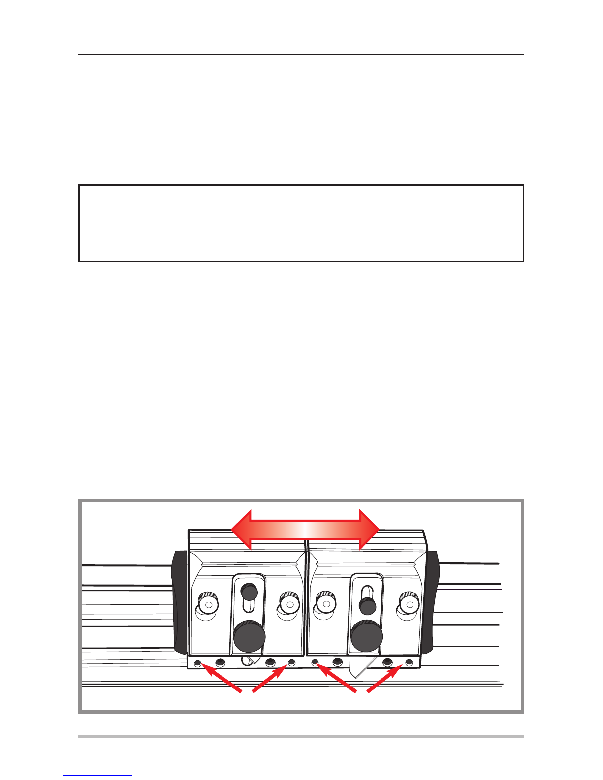
It is good practice to keep a dust sheet over the cutter if it is not to be used for extended periods. In any event regularly clean it with a dry cloth, to remove any stubborn stains
use a cloth dampened with a little water/detergent.
Should the cutting head slideway require lubrication use a silicon spray or impregnated
sponge.
CUTTING HEAD BEARINGS
The bearings that control the sliding motion of the cutting head are manufactured from a
high grade polymer and under normal use will last for an extremely long time. As they
settle into position you may find a slight amount of side play, this can be removed by
tightening the two adjustment screws:
Place the long end of the 2mm Allen key provided into any of the two screws
J
and
very gradually tighten it with one hand whilst moving the cutting head up and down the
cutter bar with the other. Once you feel the sliding motion start to tighten undo the
screw the smallest amount so the cutting head just slides easily.
Repeat this on the other screw, further finer adjustment on each screw may be needed
to achieve an easy sliding movement with zero side play.
■ Please note! Do not use oil or spirits to lubricate or clean the cutter, some of
the plastic components and bearings may be damaged.
J
KEENCUT Limited
E-mail: [email protected]
KEENCUT Limited accepts no liability if the product is not assembled and used in the correct way.
J
 Loading...