

BBiigg Bench
ASSEMBLY INSTRUCTIONS
Thank you for choosing the Keencut Big Bench.
Every effort has been made to bring you a superbly
built product with the promise of many years of
good service.
Keencut – the world’s finest cutting machines
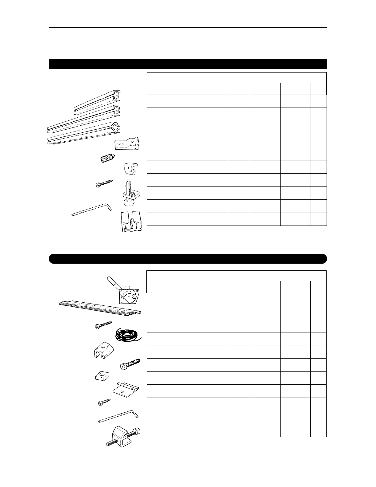
2 Packing List 2
You should have;
Packed in the Rectangular Boxes:
Short beam 4 6 8 10
Long beam 4 8 12 16
Leg 4 6 8 10
Joining Bracket 16 28 40 52
Grub Screw 48 84 120 156
Worktop Fixing 4 6 8 10
Long Screw 4 6 8 10
Height Adjuster 4 6 8 10
4mm Hexagon Wrench 1 1 1 1
Spacer 1 1 1 1
QUANTITY FOR BIG BENCH
ITEM
1.0,1.5 2.0, 2.5, 3.0 3.5, 4.0, 4.5 5.0
Packed in the TUBE:
Lift & Hold (Left & Right) (1,1) (1,1) (1,1) (1,1)
Base Extrusion 1 1 1 1
Large Screw 6 6 6 6
Silicon Cord 1 1 1 1
Base Clamp 2 3 4 5
Cap Screw 2 3 4 5
Square Nut 2 3 4 5
Worktop Connector 2 4 6 8
Small Screw 2 4 6 8
5mm Hexagon Wrench 1 1 1 1
Levelling Bracket & Screw 2 4 6 8
QUANTITY FOR BIG BENCH
ITEM
1.0,1.5 2.0, 2.5, 3.0 3.5, 4.0, 4.5 5.0
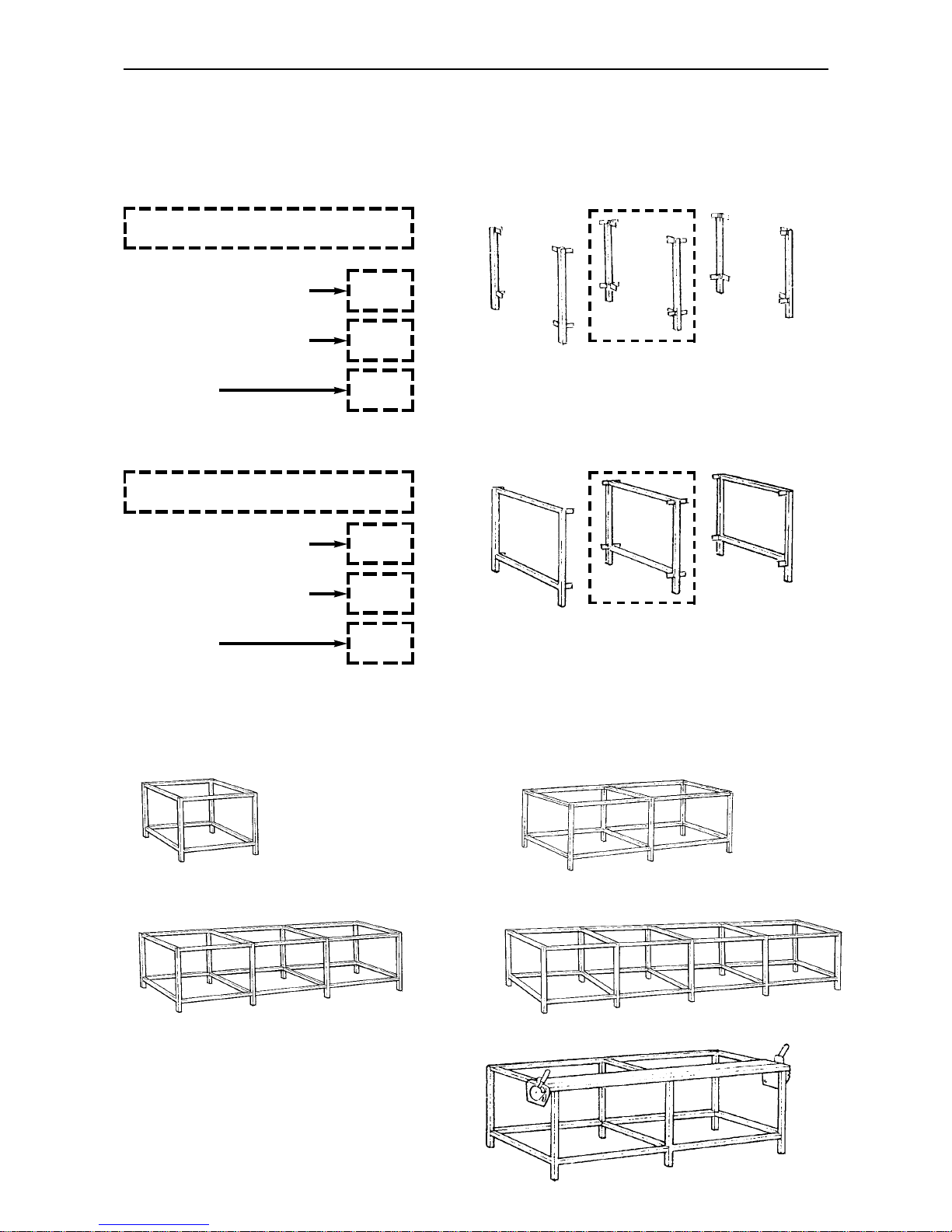
3 Order of Assembly 3
The Order of assembly is important – the following diagrams are for quick reference
only and are to enable the reader to familiarise themselves with the general assembly of
the Big bench, the detailed assembly is described in 4 stages.
Stage 1
Fix the brackets to the legs.
The 1.0m & 1.5m Big bench have only 4 legs,
please disregard the middle pair of legs.
x1
x1
x1
Stage 2
Construct the end frames.
Disregard the middle frame if you are building
a 1.0m or 1.5m Big bench.
2.0m, 2.5m & 3.0m Big bench
x2
3.5m, 4.0m & 4.5m Big bench
x3
5m Big bench
x1
2.0m, 2.5m & 3.0m Big bench
x2
3.5m, 4.0m & 4.5m Big bench
x3
5m Big bench
Stage 3
Join the end frames and cross beams to produce the bench.
Middle legs
Middle frame
1.0 & 1.5 Big bench 2.0, 2.5 & 3.0m Big bench
3.5, 4.0 & 4.5m Big bench 5m Big bench
Stage 4
Attach the Javelin lift & hold mechanisms
and base extrusion.

Stage 1
1. Put a grub screw backwards into each of the joining brackets – do not place screws in the
other holes.
NOTE:
The following instructions will assume the Big bench has six legs (2.0, 2.5 or 3.0). If
you are constructing a (1.0 or 1.5) Big bench please omit the middle frame.
✗
✗
✗
✓
➤
a
2. Using the spacer, fit the brackets to the top of
each leg as shown – ensure:
a). The brackets are fitted the correct
way round.
b). The spacer is slightly above the top
level of the leg, so when
constructed the top level of the leg
is not above the beam.
c). The grub screws are tightened fully.
3. Attach brackets to the
bottom of the legs (and the
same way round as shown
above), using a tape measure
or spacer to position them to
suit your requirements.
a
✗
✔
3.1 Assembly 3.1

Stage 2
1. Fit the two short beams between
each pair of leg assemblies
ensuring the small groove in the
beam is uppermost.
2. Pulling the two legs
together (to close
any gaps between
the end of the beam
and the legs) tighten
all the grub screws.
Stage 3
1. Place one end frame on the floor with the
brackets pointing upwards and position
a long beam over each bracket (again
ensure the small groove in the beam will
be uppermost).
2. Place either:
the other end frame (if you are
constructing a 1.0m or 1.5m
big bench)
or
The centre frame (if you are constructing
a 2.0m, 2.5m or 3.0m Big bench)
over the beams and tighten the grub screws
ensuring there are no gaps between the beam
ends and the legs.
3. 2.0m, 2.5m or 3.0m
Big bench only
Stand the frame onto its feet
and position the remaining
long beams between the
frame and the remaining end
frame, tighten all the grub
screws again ensuring there
are no gaps between the
beam ends and the legs.
TOP
3.2 Assembly 3.2
4. Put grub screws in each of
the two large holes of the
bracket, only screw them in
2 or 3 turns.
5. Fix the height adjusters into
the bottom of each leg.
Position the adjuster in one of
the internal grooves of the leg
(ie. the same groove the
brackets are fitted).
Position the bottom
of the aluminium
bracket level with
the bottom of the
leg and tighten the
grub screw fully.
TOP

3.3 Assembly 3.3
Stage 4
1. Place the base extrusion on the edge of the
bench so the lip hangs over the front edge of the
legs. Slide the square nuts into the recess as
shown and place one near to each leg. Slide the
workshop fixing plates into their groove and
position them at approximately equal spaces along
the base extrusion.
2. Using the 5mm hexagon wrench fix the base
extrusion in place on the bench with the base
clamps and cap screws.
3. Fix the lift & hold mechanisms to each end of the
base extrusion with three self taping large
screws on each end, do not at this stage tighten
the screws fully.
View from underneath
SQUARE
NUT
WORKTOP
FIXING PLATE

ba
3.4 Assembly 3.4
Stage 4 – cont’d
4. Fix the Worktop in place using
a) The large workshop fixing and large
screws as shown.
b) the small screws to fix the worktop
fixing plates.
5. Position the Javelin cutter onto the two
lift & hold mechanisms by sliding the
tongue into the slot inside the end caps
of the Javelin.
6. Move the cutting head to one end of
the Javelin and depress the blade,
adjust the position of the lift & hold
mechanism so the blade runs centrally
in the slot on the base extrusion,
tighten the three screws to fasten the
lift & hold.
Repeat for the other end.
Move lift & hold to align
blade in slot
Position brackets approximately
as shown
NOTE:
The friction knob on each mechanisms can
be adjusted to hold the Javelin at any height
which makes accurate lining up easier when
in use.
7. Position the bench in place and using an accurate spirit level adjust the feet to ensure the top
surface of the table is flat. If the table is not flat, particularly along it’s length, there may be difficulty
in holding the workpiece in place along the full cut length.
Plan View

3.5 Assembly 3.5
8. If a thin film or paper is being cut check that the material can be gripped along the full length of the
bench. Pass a small piece of the material about 25cm (10") wide under the cutter and ensure it is
held in place, carry this out along its full length.
Should the cutter not grip adjacent to a bench leg, adjust the foot to slightly raise that part of the
bench and test again.
Should the paper not be gripped by the cutter bar between the legs, place a levelling bracket and screw
in the beam on the underside of the base extrusion. Position it in the middle of the area that is not
clamping and tighten the screw until the paper is clamped efficiently. Check the whole cutter bar is
clamping, add more levelling brackets and adjust if necessary.

KEENCUT Limited
Baird Road, Willowbrook Industrial Estate,
Corby, Northamptonshire UK, NN17 5ZA.
Tel: +44 (0) 1536 263158 Fax: +44 (0) 1536 204227
E-mail: info@keencut.co.uk
KEENCUT INC. (North American Sales)
366-3560 Pine Grove Ave. Port Huron, Michigan,
48060 USA.
Toll Free: 1 800 240 KEEN (5336)
Tel: 1 (519) 652 0970 Fax: 1 (519) 652 0396
E-mail: northamericansales@keencut.com
www.keencut.co.uk
INSPIRED DESIGN –PRECISION ENGINEERING
 Loading...