

Page 1

Vantage Plus and Vantage Plus LED
Indirect Ophthalmoscope
Instructions for use
1
Page 2

Contents:
1. Copyright and trademarks................................. Page
2. Introduction.......................................................
Product description..................................
3. Symbols..............................................................
4. Safety.................................................................
Device classification
Warnings
Cautions...................................................
Safety considerations...............................
5. Setting up and using the Vantage Plus..............
Controls and components
Headband adjustment.............................
Ophthalmoscope alignment
Interpupillary distance setting control
Obtaining a fused image
Mirror angle control
Head dimmer switch
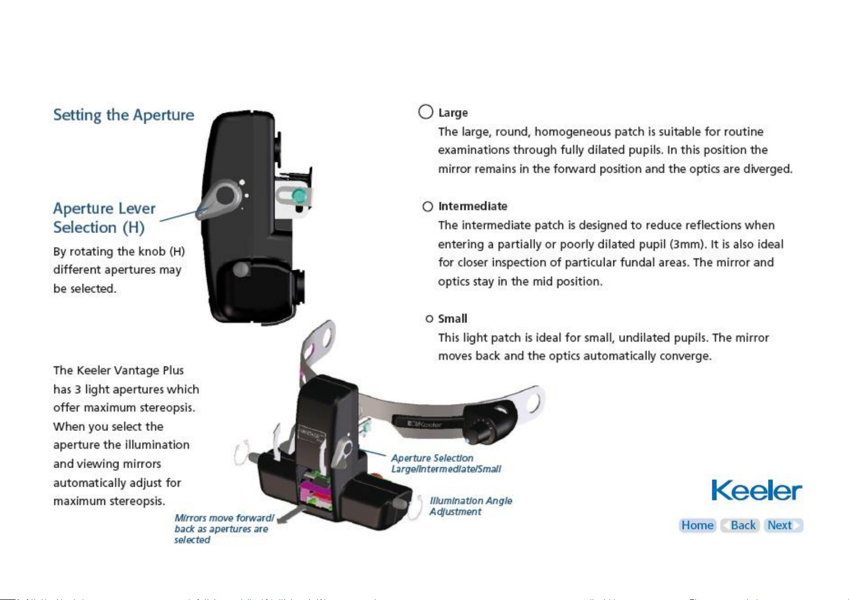
Setting the aperture................................
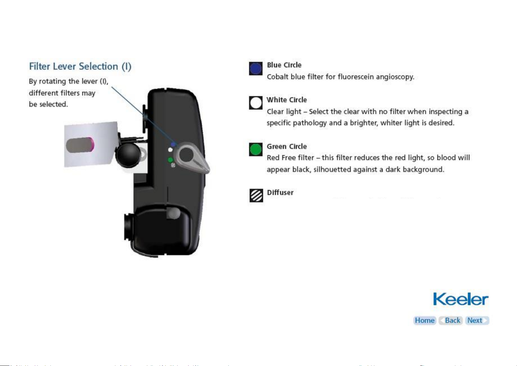
Selecting filters........................................
3
4
5
6
7
8
9
10
11
12
13
6. Wireless chargers............................................... Page
Power supply...........................................
Standard lithium......................................
Slimline lithium ion..................................
Charging and charging cycle....................
Wall mounting.........................................
7. SmartPack and WallPack...................................
Parts list
Power conversion....................................
Wall mounting / charging........................
LED displays.............................................
8. LED / bulb replacement.....................................
9. Cleaning instructions.........................................
10. Specifications and electrical ratings..................
Electrical specifications
Transport, storage and operation
11. Annex I – EMC statement and guidelines.........
12. Spare parts and accessories..............................
13. Warranty............................................................
14. Contact and disposal information....................
14
15
16
17
20
22
23
24
25
26
27
28
29
34
37
38
Click on the headings above to go directly to that section
Use the buttons on the right to navigate the document
Clicking ‘Home’ from any page brings you back to this contents page
2
Page 3

1 . Copyright and trademarks
The information contained within this manual must not be
reproduced in whole or in part without the manufacturer’s prior
written approval.
As part of our policy for continued product development we
reserve the right to make changes to specifications and other
information contained in this document without prior notice.
Vantage Plus and Vantage Plus LED are a registered trademark of
Keeler Ltd 2012
Copyright © Keeler Limited 2012
Published in the UK 2012
3
Page 4

2. Introduction
Thank you for purchasing the Keeler Vantage Plus Indirect
Ophthalmoscope.
We have taken the greatest care in the design, development and
manufacture of this product to ensure that you get many years of
trouble free service. However, it is important that you read the
descriptions, installation and operating instructions carefully prior
to installing or using your new indirect ophthalmoscope.
Please read and follow these instructions
carefully.
4
Page 5
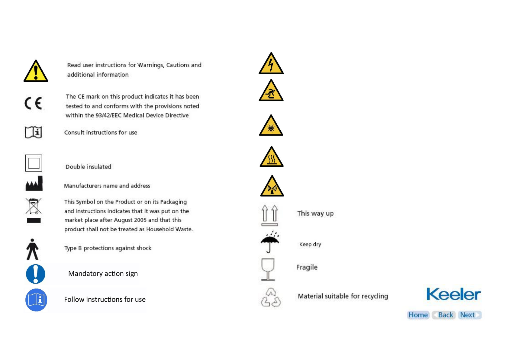
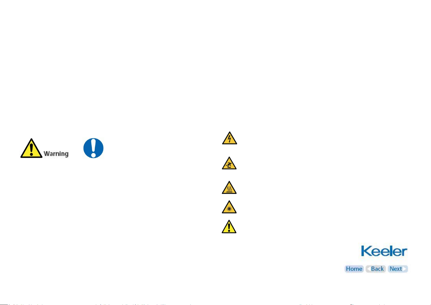
3. Symbols
High voltage
Trip hazard
Optical radiation hazard
Hot surface
Non-ionizing radiation
5
Page 6
4. Safety
Device classification
CE Regulation 93/42 EEC: Class I
FDA: Class II
Carefully read this Instruction Section before using your Keeler product.
For your own safety and that of your customers observe all cautionary
information provided in this section. The following information is
intended to highlight potential safety hazards that can be associated
with misuse, or damage
Warnings and cautions
Check your Keeler product for signs of transport / storage damage prior
to use
Do not use if the product is visibly damaged, and periodically inspect
for signs of damage
Do not use in the presence of flammable gases / liquids, or in an oxygen
rich environment
This product should not be immersed in fluids
Do not disassemble or modify the battery. There are no serviceable
parts inside
Do not dispose of battery in fire, puncture or short circuit
Do not use a battery that is deformed, leaking, corroded or visually
damaged. Handle a damaged or leaking battery with care. If you come
into contact with electrolyte, wash exposed area with soap and water.
If it contacts the eye, seek medical attention immediately
US Federal law restricts this device to sale by or order of a physician or
practitioner
Do not fit mains power adapter into a damaged mains
outlet socket
Route power cords safely to eliminate risk of tripping or
damage to equipment
Bulbs / LED’s can reach high temperatures in use – allow
to cool before handling
Do not exceed maximum recommended exposure time
After removal of the bulb / LED do not touch the bulb /
LED contacts and the patient simultaneously
6
Page 7

4. Safety
Use only genuine Keeler approved parts and accessories or device
safety and performance may be compromised
Use only Keeler approved batteries, chargers and power supplies as per
the accessories listed in section 12
The product has been designed to function safely when at an ambient
temperature between +10°C and +35°C
Keep out of the reach of children
To prevent condensation from forming, allow instrument to come to
room temperature before use
For indoor use only (protect from moisture)
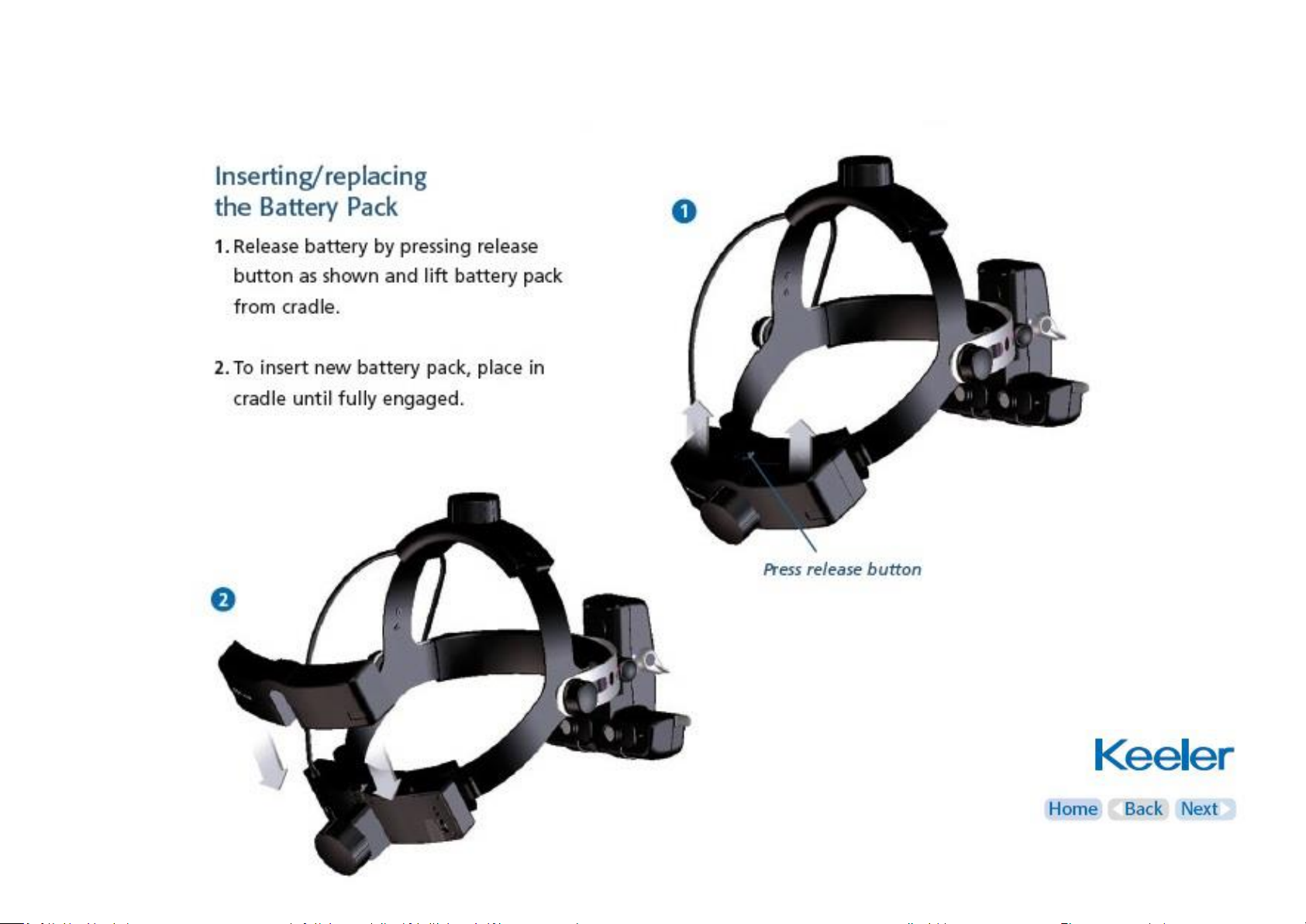
When replacing lithium battery pack, turn indirect off and attach new
pack
Remove batteries when device may not be used for prolonged periods
Do not charge battery in any environment where the temperature may
exceed 40˚C or fall below 0˚C
There are no user serviceable parts inside. Contact authorised service
representative for further information
Ensure battery orientation is correct, or personal injury / damage to
equipment may occur
Care should be taken when handling halogen bulbs. Halogen bulbs can
shatter if scratched or damaged
Ensure device is securely held in docking station to minimise risk of
injury or damage to equipment
Follow guidance on cleaning / routine maintenance to prevent personal
injury / damage to equipment
Switch off the electrical supply and disconnect from the
mains electrical supply before cleaning and inspection
Dispose of batteries in line with local environmental regulations
At product end of life dispose of in accordance with local
environmental guidelines (WEEE)
Note: Lithium Ion batteries contain no toxic heavy metals
such as mercury, cadmium or lead
7
Page 8

4. Safety
Safety considerations
It is well established that exposure of the eye to intense light
sources for extended periods of time poses a risk of retinal photic
injury. Many ophthalmic instruments illuminate the eye with
intense light. The decision about the intensity of the light level to
use in any procedure must be made on a case to case basis. In
each case, the clinician must take a risk benefit judgement about
the intensity of light to be used. Use of insufficient intensity may
result in inadequate visualization and in adverse effects more
serious than retinal photic damage. Further, despite all efforts
taken to minimise the risk of retinal damage, damage may still
occur. Retinal photic injury is a possible complication of the need
to use bright light clearly visualize ocular structure during delicate
ophthalmic surgical procedure.
While no visible retinal lesions have been identified for
ophthalmic instruments, it is recommended that illumination
levels be set to the minimum level necessary to perform the
diagnostic function. Young children and persons with diseased
eyes may be at a higher risk. The risk may also be increased if the
person being examined has had any exposure with the same
instrument or any other ophthalmic instrument using an intense
visible light source during the previous 24 hours. This will apply
particularly if the eye has been exposed to retinal photography.
The light emitted from this instrument is potentially hazardous.
The longer the duration of exposure, the greater the risk of
ocular damage. Exposure to light from this instrument when
operated at maximum intensity will exceed the safety guideline
after 27 minutes.
8
Page 9

5. Setting up and using the Vantage Plus
9
Page 10

5. Setting up and using the Vantage Plus
Headband Adjustment
Comfortable Fit
Adjust the size (A) fig.1 and the height (B) fig.2, so
that the instrument is supported comfortably
around and on top of the head.
Ophthalmoscope Angle Alignment
For vertical alignment of the eyepieces and
binocular block (O), adjust the height of the Metal
Outer Brow Bar (C) if necessary by using the
browband tension knobs (D) located on the sides
of the headset (fig 3).
Position the Binocular Block (O) as close to the
eyes or spectacles as possible for maximum field of
view. Slightly loosen the ophthalmoscope angle
knob (E) to allow for adjustment and tighten when
in position as in (fig 4).
10
Page 11

5. Setting up and using the Vantage Plus
Interpupillary Distance Setting Control (S)
Because the eyes are dissociated, particular care must be taken to
ensure the optics (eyepieces) are set properly in front of each eye.
Always set the Aperture Selection (H) to the large light patch for
this exercise.
Place an object, perhaps the thumb, approximately 40cm from the
face and centre it horizontally in the light patch. Then, close one
eye. Using the thumb and forefinger of the opposite hand, slide
the P.D.Control (S) of the open eye (located directly under each
eyepiece) so that your object moves into the centre of the field,
keeping the object in the centre of the light patch. Repeat for the
other eye.
Obtaining a fused image
Ensure that a singular, fused image is obtained as follows:
Mirror Angle Control (J)
The light is positioned vertically into the upper two thirds of the
field of view by rotating the spindle (J) located on either side of
the binocular block.
Head Dimmer Switch (T)
Turn the illumination on by rotating the headband dimmer (T)
in an anti clockwise direction.
11
Page 12
5. Setting up and using the Vantage Plus
12
Page 13
5. Setting up and using the Vantage Plus
This unique extra wide beam of diffused light permits a more
relaxed technique during more challenging fundus
examinations.
Beginners may also find this aperture particularly helpful
since, in order to achieve a full lens image, the alignment
between the headset, the condensing lens and the pupil is
13
Page 14

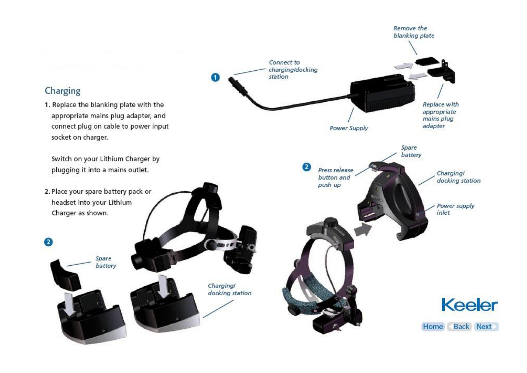
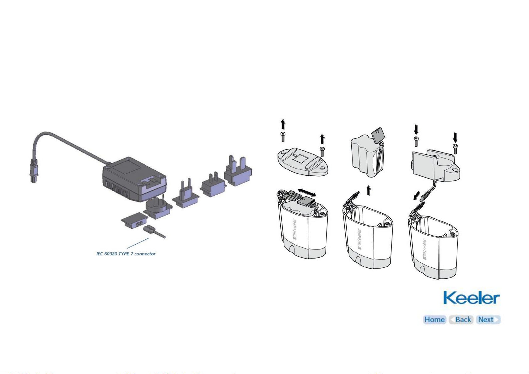
6. Wireless chargers – power supply assembly
Set plug
Replace the blanking plate with the appropriate mains plug
adaptor if required, or use IEC 60320 TYPE 7 connector (not
supplied).
14
Page 15
6. Wireless chargers – Standard Lithium
15
Page 16

6. Wireless chargers – Slimline Lithium-ion
16
Page 17
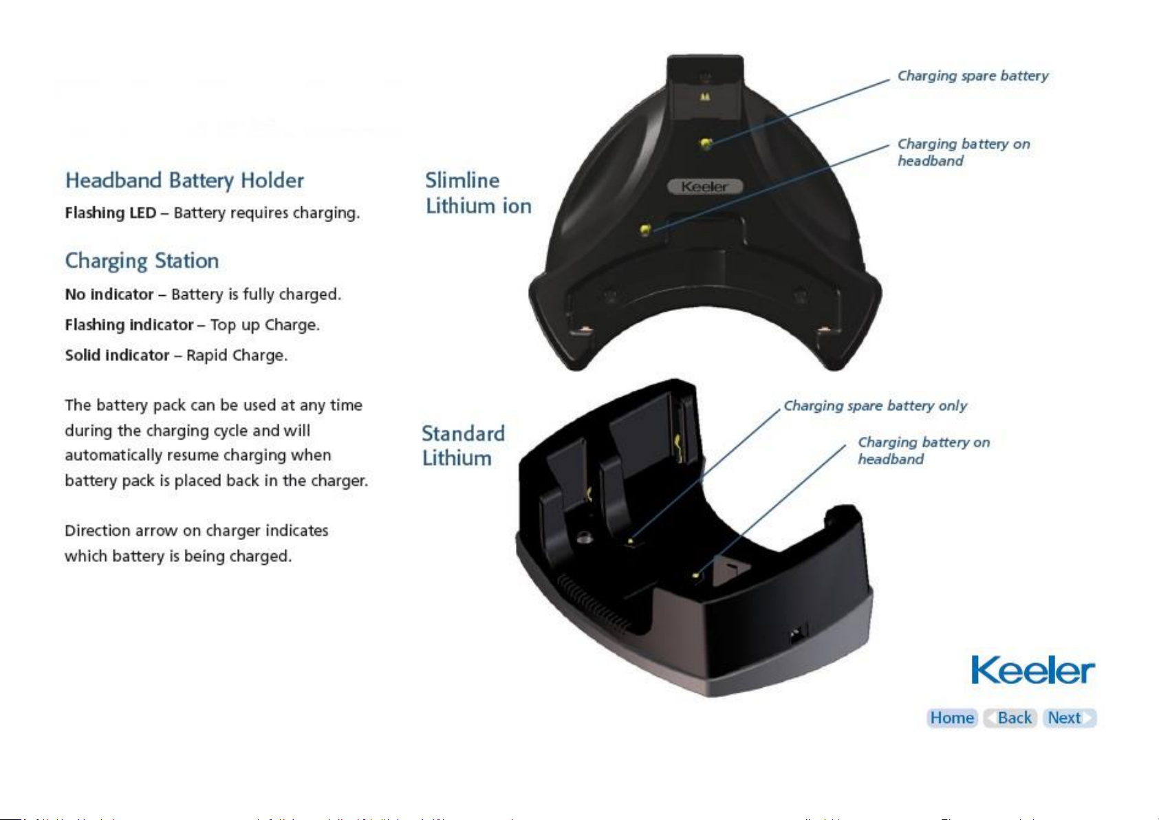
6. Wireless chargers
17
Page 18
6. Wireless chargers
18
Page 19

6. Wireless chargers
Charging Cycle - Standard Lithium
The battery attached to the indirect will take approximately 2
hours to fully charge.
The battery will last approximately 2 hours on full power.
The spare battery will take 4 hours to charge.
Charging Cycle - Slimline Lithium ion
The battery attached to the indirect will take approximately
1½ hours to fully charge.
The battery will last approximately 1 hour on full power.
The spare battery will take 1½ hours to charge.
19
Page 20

6. Wireless chargers – wall mounting
20
Page 21

6. Wireless chargers – wall mounting
21
Page 22

7. SmartPack and WallPack
22
Page 23
7. SmartPack and WallPack
Set Plug
Assemble the power supply as per the instructions in section 6.
Power conversion
Convert to either WallPack or SmartPack by following the
illustration below.
23
Page 24

7. SmartPack and WallPack
24
Page 25

7. SmartPack and WallPack
25
Page 26

8. LED / bulb replacement
26
Page 27

9. Cleaning
Only manual non-immersion cleaning as described should be used
for this instrument
Do not autoclave or immerse in cleaning fluids
Always disconnect power supply from source before cleaning
a Wipe the external surface with a clean absorbent, nonshedding cloth dampened with a water / detergent solution (2%
detergent by volume) or water / isopropyl alcohol solution (70%
IPA by volume). Avoid optical surfaces
b Ensure that excess solution does not enter the instrument.
Use caution to ensure cloth is not saturated with solution
c Surfaces must be carefully hand-dried using a clean nonshedding cloth
d Safely dispose of used cleaning materials
27
Page 28

10. Specifications and electrical ratings
Input mains data: 100-240V – 50/60Hz
Power supply rating: 12V : 2.5amps
Operation: Continuous
Classification: Class II equipment
Type B protection against shock
Transport, storage and operating conditions
Transport
Storage
Operation
Temperature
range
-40°C
to +70°C
-10°C
to +55°C
+10°C
to +35°C
Relative
humidity
10% to 95%
10% to 95%
30% to 75%
Atmospheric
pressure
500hPa
to 1060hPa
700hPa
to 1060hPa
700hPa
to 1060hPa
28
Page 29

11. Annex I – EMC statement and guidelines
The Keeler Vantage Plus / Vantage Plus LED is a medical electrical instrument. The instrument requires special care concerning electromagnetic
compatibility (EMC). This section describes the suitability in terms of electromagnetic compatibility of this instrument. When installing or using this
instrument, please read carefully and observe what is described here.
Portable or mobile-type radio frequency communication units may have an adverse effect on this instrument, resulting in malfunctioning.
29
Page 30

11. Annex I – EMC statement and guidelines
Guidance and manufacturer’s declaration – electromagnetic immunity
The Keeler Vantage Plus LED is intended for use in the electromagnetic environment specified below. The customer or the user should assure that it is used in
such an environment.
Immunity test
IEC 60601 Test level
Compliance level
Electromagnetic environment - guidance
Electrostatic
discharge (ESD).
IEC 61000-4-2
± 6 kV contact
± 8 kV air
± 6 kV contact
± 8 kV air
Floors should be wood, concrete or ceramic tile.
If floors are covered with synthetic material, the relative
humidity should be at least 30%.
Electrical fast
transient/burst.
IEC 61000-4-4
± 2 kV for power supply lines
± 1 kV for input/output lines
± 2 kV for power supply lines
N/A
Mains power quality should be that of a typical commercial or
hospital environment.
Surge.
IEC 61000-4-5
± 1 kV line(s) to line(s)
± 2 kV line(s) to earth
± 1 kV line(s) to line(s)
N/A
Mains power quality should be that of a typical commercial or
hospital environment.
Voltage dips, short
interruptions and
voltage variations on
power supply input
lines.
IEC 61000-4-11
<5% UT
(> 95% dip in UT) for 0.5 cycles
40% UT
(60% dip in UT ) for 5 cycles
70% UT
(30% dip in UT ) for 25 cycles
<5% UT
(>95% dip in UT) for 5 s
<5% UT
(> 95% dip in UT) for 0.5 cycles
40% UT
(60% dip in UT) for 5 cycles
70% UT
(30% dip in UT) for 25 cycles
<5% UT
(>95% dip in UT ) for 5 s
Mains power quality should be that of a typical commercial or
hospital environment.
If the user of the Keeler Vantage Plus LED requires continued
operation during power mains interruptions, it is recommended
that the charger be powered from an uninterruptible power
supply.
Power frequency
(50/60 Hz) magnetic
field. IEC 61000-4-8
3 A/m
3 A/m
Power frequency magnetic fields should be at a level
characteristic of a typical location in a typical commercial or
hospital environment.
Note UT is the a.c. mains voltage prior to application of the test level.
30
Page 31

11. Annex I – EMC statement and guidelines
Guidance and manufacturer’s declaration – electromagnetic emissions
The Keeler Vantage Plus LED is intended for use in the electromagnetic environment specified below. The customer or user should assure that it is used in such an
environment.
Emissions test
Compliance
Electromagnetic environment - guidance
Charger only
RF emissions
CISPR 11
Group 1
The Keeler Vantage Plus LED uses RF energy only for its internal function.
Therefore, its RF emissions are very low and are not likely to cause any
interference in nearby electronic equipment.
RF emissions
CISPR 11
Class B
The Keeler Vantage Plus LED is suitable for use in all establishments,
including domestic establishments and those directly connected to the
public low-voltage power supply network that supplies buildings used for
domestic purposes.
Harmonic emissions
IEC 61000-3-2
Class A
Voltage fluctuations /
flicker emissions
IEC 61000-3-3
Complies
Indirect
Ophthalmoscope only
RF emissions
CISPR 15
Complies
The Keeler Vantage Plus LED is not suitable for interconnection with other
equipment
31
Page 32

11. Annex I – EMC statement and guidelines
Guidance and manufacturer’s declaration – electromagnetic immunity
The Keeler Vantage Plus LED is intended for use in the electromagnetic environment specified below. The customer or user should assure that it is used in such an
environment.
Immunity test
IEC 60601 Test level
Compliance level
Electromagnetic environment - guidance
Conducted RF
IEC 61000-4-6
Radiated RF
IEC 61000-4-3
3 Vrms
150 kHz to 80 MHz
3 V/m
80MHz to 2.5GHz
3 V
3 V/m
Portable and mobile RF communications equipment should be used no
closer to any part of the Keeler Vantage Plus LED, including cables, than the
recommended separation distances calculated from the equation applicable
to the frequency of the transmitter.
Recommended separation distance
d = 1.2 √ p
d = 1.2 √ p 80MHz to 800 MHz
d = 2.3 √ p 800MHz to 2.5GHz
Where p is the maximum output power rating of the transmitter in watts(W)
according to the transmitter manufacturer and d is the recommended
separation distance in metres(m).
Field strengths from fixed RF transmitters, as determined by an
electromagnetic site survey¹, should be less than the compliance level in
each frequency range.²
Interference may occur in the vicinity of
equipment marked with the following symbol:
Note 1 At 80MHz and 800MHz, the higher frequency range applies.
Note 2 These guide lines may not apply in all situations. Electromagnetic propagation is affected by absorption and reflection from structures, objects and people.
¹ Field strengths from fixed transmitters, such as base stations ( cellular / cordless) telephones and land mobile radios, amateur radio, AM and FM radio broadcast
and TV broadcast cannot be predicted theoretically with accuracy. To assess the electromagnetic environment due to fixed RF transmitters, an electromagnetic site
survey should be considered. If the measured field strength in the location in which the Keeler Vantage Plus LED is used exceeds the applicable RF compliance level
above, the instrument should be observed to verify normal operation. If abnormal performance is observed, additional measures may be necessary, such as reorientating or relocating the Keeler Vantage Plus LED.
² Over the frequency range 150kHz to 80 MHz, field strengths should be less than 3 V/m.
32
Page 33

11. Annex I – EMC statement and guidelines
Recommended separation distances between portable and mobile RF communications equipment and the Keeler Vantage Plus LED
The Keeler Vantage Plus LED is intended for the use in an electromagnetic environment in which radiated RF disturbances are controlled. The customer or the
user of the Keeler Vantage Plus LED can help prevent electromagnetic interference by maintaining a minimum distance between portable and mobile RF
communications equipment (transmitters) and the Keeler Vantage Plus LED as recommended below, according to the maximum output power of the
communications equipment.
Rated maximum
output power of
transmitter
W
Separation distance according to frequency of transmitter
m
150 kHz to 80MHz
d = 1.2√ p
80MHz to 800MHz
d = 1.2√ p
800MHz to 2.5GHz
d = 2.3√ p
0.01
0.12
0.12
0.23
0.1
0.37
0.37
0.74
1
1.2
1.2
2.3
10
3.7
3.7
7.4
100
12
12
23
For transmitters rated at a maximum output power not listed above, the recommended separation distance d in metres (m) can be determined using the
equation applicable to the frequency of the transmitter, where p is the maximum output power rating of the transmitter in watts (W) according to the transmitter
manufacturer.
Note 1 At 80MHz and 800MHz, the higher frequency range applies.
Note 2 These guide lines may not apply in all situations. Electromagnetic propagation is affected by absorption and reflection from structures, objects and
people.
33
Page 34

12. Spare parts and accessories
The following accessories are typical of those supplied in the kits
as indicated:
Vantage Plus Bulb version:
Wired (eg. 1204-P-3051)
Part Number
Description
EP39-53748
Eye Lens Plano (qty 2)
EP39-53799
Rubber Eye Cap (qty 2)
1202-P-7192
HiMag Assembly
2199-P-7136
Lens Cloth
1012-P-5241
Bulb
2415-P-7001
Instructions for Use CD
Wireless, with standard battery and charger (eg. 1204-P-3056)
As for 1204-P-3051 example, plus:
Part Number
Description
EP29-32777
Power supply
EP39-22706
Wall pad
EP59-49013
Wall mount template
EP79-06498
Rawlbloc wall plug (qty 2)
SP90-84030
Screws (qty 2)
1012-P-5241
Bulb
1919-P-1013
Battery pack
1941-P-5334
Standard charger
2415-P-7000
Instructions for use CD
Wireless, with slimline battery and charger (eg. 1204-P-3067)
As for 1204-P-3051 example, plus:
Part Number
Description
EP29-32777
Power supply
EP39-22706
Wall pad
EP59-49005
Wall mount template
EP79-06498
Rawlbloc wall plug (qty 3)
EP79-09496
Rubber foot (qty 3)
SP90-82000
Wood screw (qty 3)
1919-P-5338
Slimline battery (1 fitted, 1 bagged)
1945-P-5019
Slimline charger
34
Page 35

12. Spare parts and accessories
Vantage Plus LED:
Wired (eg. 1205-P-1010)
Part Number
Description
EP39-53748
Eye Lens Plano (qty 2)
EP39-53799
Rubber Eye Cap (qty 2)
1202-P-7192
HiMag Assembly
2199-P-7136
Lens Cloth
2415-P-7001
Instructions for Use CD
Wireless, with standard battery and charger (eg. 1205-P-1019)
As for 1205-P-1010 example, plus:
Part Number
Description
EP29-32777
Power supply
EP39-22706
Wall pad
EP59-49013
Wall mount template
EP79-06498
Rawlbloc wall plug (qty 2)
SP90-84030
Screws (qty 2)
1919-P-1013
Battery pack (1 fitted, 1 bagged)
1941-P-5334
Standard charger
Wireless, with slimline battery and charger (eg. 1205-P-1020)
As for 1205-P-1010 example, plus:
Part Number
Description
EP29-32777
Power supply
EP39-22706
Wall pad
EP59-49005
Wall mount template
EP79-06498
Rawlbloc wall plug (qty 3)
EP79-09496
Rubber foot (qty 3)
SP90-82000
Wood screw (qty 3)
1919-P-5338
Slimline battery (1 fitted, 1 bagged)
1945-P-5019
Slimline charger
35
Page 36

12. Spare parts and accessories
36
Page 37

13. Warranty
No user serviceable parts – all preventative maintenance and
servicing must only be performed by authorised Keeler
representatives
Your Keeler product is guaranteed for 3 years and will be replaced,
or repaired free of charge subject to the following:-
• Any fault due to faulty manufacture
• The instrument and accessories have been used in compliance
with these instructions
• Proof of purchase accompanies any claim.
Please note:
The LED for the Vantage Plus LED models is guaranteed for 5
years.
Batteries are covered by this warranty statement for 1 year only.
37
Page 38

14. Contact and disposal information
Keeler Limited
Clewer Hill Road
Windsor
Berkshire SL4 4AA
Freephone: 0800 521251
Tel: +44 (0)1753 857177
Fax: +44 (0)1753 827145
Keeler Instruments Inc.
3222 Phoenixville Pike
Building #50
PA 19355, USA
Toll Free: 1 800 523 5620
Tel: 610 353 4350
Fax: 610 353 7814
Disposal of old Electrical and Electronic Equipment
(Applicable in the European Union and other European Countries
with separate Collection Systems)
To Reduce the Environmental impact of WEEE (Waste Electrical
Electronic Equipment) and minimise the volume of WEEE entering
landfills we encourage at Product end of life that this Equipment is
recycled and reused.
If you need more information on the collection reuse and
recycling then please contact B2B Compliance on 01691 676124
(+44 1691 676124)
EP59-19017 issue F
38
 Loading...