

Page 1
INDIRECT
POWER SUPPLY
Instructions
English
PLEASE READ AND FOLLOW THESE INSTRUCTIONS CAREFULLY
Page 2

Contents
Section one
Preparing your Indirect Ophthalmoscope Power Supply
1.1
Contents Check
1.2
Electrical Check
1.3
Fitting Instructions for Desk-Top Systems
1.4
Fitting Instructions for In-Case Use
1.5
Fitting Instructions for Wall Mounted Systems
Section two
Standard Operating Instructions
2.1
Connecting your instrument to your wall mounted power supply
2.2
Connecting your rechargeable battery for charging
2.3
Connecting your rechargeable battery for use
2.4
Usage Guide
Section three
Care and Maintenance
3.1
Cleaning
3.2
Maintenance
Section four
Servicing
Section five
Technical Specifications
Section six
Upgrading your Indirect Ophthalmoscope Power Supply
Page 3

Introduction
Thank you for purchasing a Keeler Indirect Ophthalmoscope
Power Supply. We have taken the greatest care in the design,
development and manufacture of these devices to ensure that
they give you many years of trouble-free service. However, it is
important that you read the descriptions, installation and operating
instructions contained in this book carefully prior to installing or
using your new Indirect Ophthalmoscope Power Supply.
If you are in doubt about any aspect of these instructions, we
recommend that you contact a qualified electrical technician, your
nearest authorised Keeler Distributor, or Keeler direct.
Indirect Ophthalmoscope Power Supply Units are for indoor
use only. Where appropriate, the plug-in power module of the
power supply unit is designed to be connected directly to a suitable
wall socket. It is important therefore that a socket is selected
where the power module will not be vulnerable to damage from
passing trolleys, etc and the low voltage interconnecting leads
should be kept away from gangways and passageways where
persons would be expected to pass.
Do not use in the presence
of fluids or flammable anaesthetics.
As part of our policy for continued product development we reserve the
right to amend specifications at any time without prior notice.
Page 4
Preparing your Indirect
Ophthalmoscope Power Supply
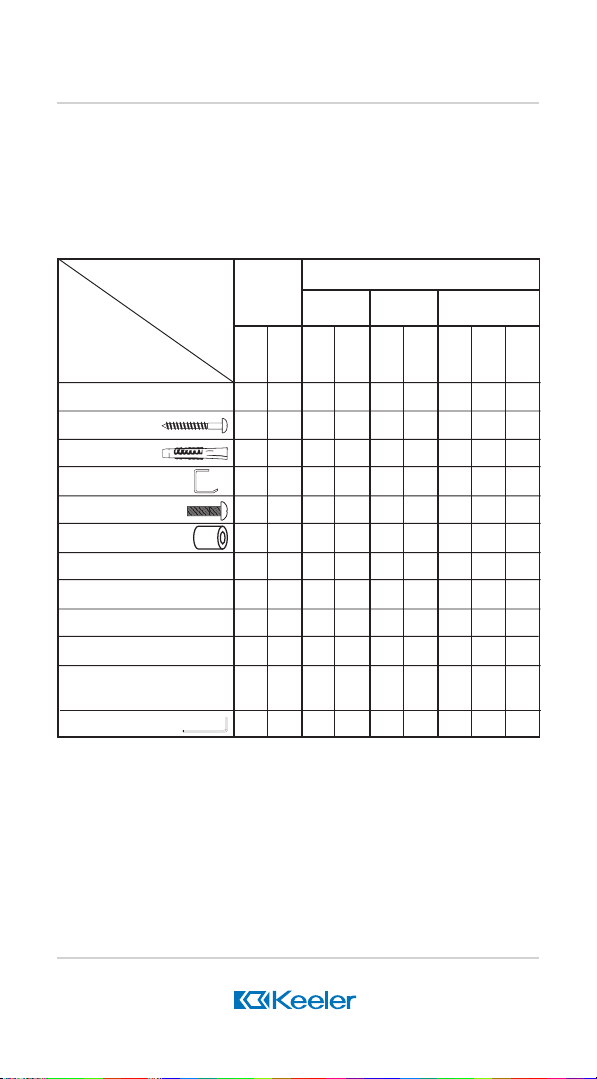
1.1 Contents Check
Before attempting to use your Vantage, All Pupil, Fison or
Spectacle Indirect Ophthalmoscope (S.I.O.) Power Supply Unit,
confirm against the contents check diagram (Fig. 1) that all the
components have been correctly supplied.
SYSTEM
COMPONENT
Power Module
Wall Screw
Wall Plug
Cradle
Cradle Securing Screw
Cradle Spacers
Battery Hanger
Rech. Battery
Battery Cable
Wall Pad
Accessory Box
Hexagonal Allen Key
Power
Supply
Units Only
S.I.OAll
Pupil
&
Fison
1 111111 11
332 33
332 33
111 11
111 11
Indirect Ophthalmoscope Kits
All Pupil(API)
& Fison
API
KIT
A & B
11 1 1
22 2 2
22 2 2
111
11 1
11 1
11 1 1
API
KIT
C & D
FISON
Fison
A only
KIT
A & B
S.I.O Vantage
KITCKIT
KIT
A
B
KIT
C
Fig 1 Contents Check Diagram
Note: The contents check diagram does not include Indirect
Ophthalmoscope components, so instructions supplied with those
instruments should be referred to. The Spectacle Indirect
Ophthalmoscope is designed for desk top use only and therefore does
not include any components for wall mounting.
Page 5

Preparing your Indirect
Ophthalmoscope Power Supply
1.2 Electrical Check
Before connecting the power unit to the electricity supply,
check that the input voltage on the data rating label corre-
sponds with that of your local supply voltage. For full electri-
cal information and circuit diagrams, refer to Section 5 - Tech-
nical Specification.
1.3 Fitting Instructions for Desk-Top Use
Keeler Indirect Ophthalmoscope Power Supply systems are
supplied ready assembled for desk-top use. Place the unit
in the desired position and plug the power module into a suit-
able power outlet/wall socket. Your power supply unit is now
ready to accept Keeler Indirect Ophthalmoscopes. Refer to
section 2 - Standard Operating Instructions.
1.4 Fitting Instructions for In Case Use
Keeler Indirect Ophthalmoscopes may be operated direct
from the case for short periods by plugging the power mod-
ule into a suitable nearby power outlet/wall socket.
CAUTION
Care should be taken not to close the case lid when the
instrument is being used in this way as this may cause
damage to the connecting cables.
Alternatively, the Indirect Ophthalmoscope Power Supply may
be removed from the case and operated from the desk or
wall mounted (see 2.1)
1.5 Fitting Instructions for Wall Mounted Systems
Important Notice: Keeler Indirect Ophthalmoscope Power
Supplies are designed to be fitted to all walls. The wall fit-
tings supplied are suitable for mounting your power supply
to walls constructed of sound brick, breeze block, concrete
Page 6

Preparing your Indirect
Ophthalmoscope Power Supply
or plasterboard. If required alternative fittings suitable
for mounting your power supply on walls constructed from
materials other than those mentioned above should be ob-
tained. If in doubt, consult a qualified builder for advice.
Keeler Limited cannot accept any responsibility for any
damage or injury sustained by incorrect assembly, wall
mounting or use of wall mounted power supplies.
The Keeler transformer unit must be disconnected from the
power supply before commencing to wall mount the unit.
a) To wall mount your Keeler Power Supply, select a convenient
position on the wall ensuring that there is a suitable power
outlet/wall socket for the plug-in power module within reach
of the interconnecting cord. Also, make sure that there are
no water or gas pipes or electrical cables buried in the wall.
b) Refer to the chart over the page (Fig.2) and identify your
power supply unit. Remove the module(s) shown from the ‘L’
shaped rail to expose the wall mounting fixing holes. This
canbe done by first removing the plastic screw hole covers
and unscrewing the retaining screws using the hex-
agonal Allen key provided. Keep the retaining screws safe
for later reassembly.
Page 7

Preparing your Indirect
Ophthalmoscope Power Supply
Kit 1
Kit 2
Kit 3
Kit 4
Transformer /
Charger only
Transformer /
Charger &
rechargeable
battery hanger
Transformer /
Charger &
Accessory box
Transformer /
Charger,
rechargeable
battery hanger
& accessory
box
Fig 2
c) Mark position of fixing
holes by using the wall
rail supplied as a
template. Check
marks are horizontal
with a spirit level. (Fig
3)
Fig 3
Page 8

Preparing your Indirect
Ophthalmoscope Power Supply
d) Drill holes to a
minimum depth of
50mm (2") with a
6mm (¼") diameter
masonry drill. (Fig 4)
Always wear eye
protection when
using a drill.
e) The wall plugs
provided are suitable
for solid or plasterboard walls. Push or
lightly tap the plugs
until they are flush
with the wall (Fig 5).
Fig 4
Fig 5
f) Screw wall rail
securely to wall using
screws provided.
(Fig 6)
g) Reassemble the
unit(s) to the wall rail
with the screws
previously removed
using the hexagonal
Allen key.
Fig 6
Page 9

Preparing your Indirect
Ophthalmoscope Power Supply
h) Replace the plastic screw hole
covers under the wall rail.
i) Secure the cradle to the power
unit using the screws and
spacers provided. (Fig 7)
j) The power module for Fison
Ophthalmoscopes and in some
markets for the All-Pupil and
Vantage Ophthalmoscopes
may also be fitted to the wall.
Follow the instructions in
section 1.5and secure the unit
with the mounting tag. (Fig 8)
Fig 7
k) Place the Indirect Ophthalmo-
scope onto the cradle and stick
the wall pad provided below the power unit, to protect the
optics from knocking
against the wall.
l) If you have a rechargeable
battery pack hanger then place
your battery onto the hanger
using the belt clip to the rear of
the battery pack. (Fig.9)
Fig 9
m) The power system is now ready
to use. Refer to section 2 Standard Operating Instruc-
Fig 8
Page 10

Standard Operating Instructions
tions.
2.1 Connecting your instrument to your wall mounted
power supply
Connect the Indirect Ophthalmoscope by inserting the multipin plug running from your Indirect Ophthalmoscope into the
All-Pupil, Vantage,
Spectacle
Fig 10a
Fison
Fig 10b
socket located on the side of your unit.
2.2 Connecting your Rechargeable battery for charging
(All Pupil, Vantage and Spectacle Indirect Ophthalmoscope only)
In order to charge the rechargeable battery connect the
battery charging cable between the battery and the right
socket located on the right hand side of the unit. (Fig.11).
Ensure the battery is turned OFF. It will now charge. Allow
16 hours to fully charge the battery from fully discharged.
IMPORTANT
For safety reasons, rechargeable
batteries are supplied in an
uncharged condition. In order to
obtain their full charge capacity,
new batteries should be
conditioned by being charged for
Fig 11
Page 11

Standard Operating Instructions
a continuous period of 24 hours.
The full charge capacity will be obtained after 3 or 4 full
charge/discharge cycles. This should also be carried out
when batteries have been stored for long periods in a fully
discharged state. After repeated charge/discharge cycles it
is possible for a reduction in battery capacity
parent. The normal capacity can be restored by a period of
extended charge (24 hours) as described for new batteries
above.
2.3 Connecting your rechargeable battery for use
The Power Supply is designed to charge the Keeler
Porta-Power 1.2Ah. 6V Ni Cad battery pack;
never be used with Non-Rechargeable batteries.
To use your battery pack unplug the charging cable at the
battery end. Unplug the Indirect Ophthalmoscope from the
power unit and plug it into the battery. (Fig 12) A fully charged
battery will provide approximately 40 minutes of full illumination. Longer periods of use may be expected if the power
and illumination are reduced.
to become ap-
and should
Usage Guide
2.4
a) Desk-top or Case
System
Turning the illumination
control on the top of the
power supply clockwise
switches the system
illuminates the light
emitting diode (LED),
and then controls the
brightness of the instru-
on
,
Fig 12
Page 12

Standard Operating Instructions
ment illumination.
When not in use the illumination
control should be turned fully
anti-clockwise until a click is
heard and the green LED is no
longer illuminated. In this
position the power supply is
(Fig 13).
b) Wall Mounted System
When not in use your instrument should rest in the cradle of
your power supply with optics downwards (Fig.14). In this
position the LED and power is off. When the control on top of
the unit is turned on, removing your instrument from the cradle powers the indirect and the LED illuminate indicating
that your instrument is now ready for use (Fig 15). Brightness of illumination is adjusted using the control on top of
the power supply.
off
Fig 13
Fig 14
Fig 15
Page 13

Care and Maintenance
Leaving the illumination on for long periods when not in use
reduces the remaining life of the Halogen Bulb in your
instrument. We therefore recommend returning the indirect
to its cradle or switching off at the control when not in use.
3.1 Cleaning
Should cleaning be required, disconnect the equipment from
the electricity supply and wipe over with a soft, dry cloth.
Do not use solvents for any cleaning purposes since these
may cause damage.
CAUTION
Never immerse the Indirect Ophthalmoscope Power
Supply unit in water or any other cleaning fluid.
If any part of the Indirect Ophthalmoscope Power Supply
should become contaminated with biological agents, please
contact Keeler Ltd direct for advice on decontamination
procedures.
3.2 Maintenance
Routine maintenance is limited to visual inspection of the
power module enclosure and interconnecting cables. Should
any damage be observed to the enclosure of the plug-in
power module or the supply cord of the Fison transformer,
discontinue use of the power supply and contact your nearest authorised Keeler Distributor. Interconnecting cables
are not replaceable by the purchaser and where repair is
required the complete power supply should be returned to
the place of purchase.
Servicing
There are no user-serviceable parts within the Indirect
Ophthalmoscope Power Supply.
Page 14

Technical Specifications
General
The Indirect Ophthalmoscope Power Supply units are class
II, double insulated devices and are classified as Type B
equipment in accordance with the degree of protection against
electric shock.
Conditions of Use
(104oF)
Conditions of
(158oF)
Storage
Note:
It is recommended that the Porta Power C should
at temperatures below 0
Fison Transformer
Power Module Dimensions 103 x 77 x 70mm (4.0 x 3.0 x 2.8
inches) Control Unit Dimensions 96.5 x 89 x 54mm (3.8 x 3.5
x 2.1 inches)
Length of Power 2m (6.6 ft)
Supply Cord
Length of 3m (9.8 ft)
Interconnecting Cord
Weight (Total) 1.415 kg (3.1 lb)
Input Voltage 100, 120, 220-240V
Temperature :10oC (50oF) to 40oC
Relative Humidity : 30% to 75%
Temperature :-20oC (-4oF) to 70oC
Relative Humidity : 10% to 100%
not
o
C (32oF)
be stored
(and Vantage/All-Pupil in some regions)
See rating plate for the nominal input voltage applicable to the
particular transformer.
Input frequency 100V unit; 50/60 Hz
Page 15

Technical Specifications
120V unit; 60Hz
220-240V units; 50Hz
Power Input 48VA
Output 6.8V, 3.2A
Vantage/All-Pupil/Spectacle Transformer/Charger
Power Module dimensions 96 x 63 x 58mm (3.8 x 2.5 x 2.3 inches)
Control Unit dimensions 87 x 89 x 54mm (3.4 x 3.5 x 2.1
inches)
Length of 3m (9.8ft)
interconnecting Cord
Weight 0.766kg (1.7 lb)
Input Voltage 100, 120, 220-240V
See rating plate for the nominal input voltage applicable to the
particular transformer.
Input frequency 100V unit; 50/60Hz
120V unit; 60Hz
220 and 240V units; 50Hz
Power Input 25VA
Output 6V , 1.7A (Indirect Ophthalmoscope)
7V dc, 100 mA
(Indirect Ophthalmoscope
Charging Output)
Page 16

Technical Specifications
Circuit Diagram for all pupil /
Spectacle Indirect Power Supply
Fig 16
Page 17

Technical Specifications
Circuit Diagram for Fison Indirect Power Supply
Fig 17
Page 18

Upgrading your Indirect
Ophthalmoscope Power Supply
All Indirect Ophthalmoscope Power Supplies have been designed
to make upgrading simple and convenient. Check Fig 18 for the
upgrade options available and how to order. For any upgrade option
not illustrated please refer to your nearest authorised dealer or Keeler
direct.
To upgrade your power supply, follow the arrow upwards from existing
unit to desired enhancement level and note numbers alongside. Refer
to list below for parts required.
Basic unit
for desk use
Desk unit & Accessory box
Wall mounted unit
When ordering a rechargeable battery for desk
& wall units with hangers, item 8 must also be
ordered. (API ,SIO & Vantage)
Wall mounted
unit with hanger
Wall mounted unit
Wall mounted
unit with
accessory box
and hanger
1
1999-P-1002 Accessory Box Kit
2
1999-P-7113 Cradle Kit
3
1999-P-7121 Battery Hanger
with hanger
(not Fison)
1999-P-7199 Rail Kit - W6
4
1999-P-7252 Hanger Ext. Kit
5
1999-P-7260 Hanger &
6
Accessory Box Kit.Ext
Fig 18
1999-P-7279 Accessory Box Ext.
7
Kit
8
1952-P-5030 Charging Cord Set
9
1999-P-1133 Wall Fixing Kit
Page 19

The CE mark on this
product indicates it has
been tested to and
conforms with the
provisions noted within
the 93/42/eec Medical
Device Directive.
MANUFACTURED BY:
Keeler Limited
Clewer Hill Road
Windsor
Berks SL4 4AA
Tel: +44 (0) 1753 857 177
Fax: +44 (0) 1753 857 817
DISTRIBUTED BY:
Keeler Instruments Inc.
456 Parkway
Broomall
PA 19008
USA
Toll Free: 1 800 523 5620
Tel: 610 353 4350
Fax: 610 353 7814
As part of our policy of continued
product development we reserve the
right to alter and/or amend specifications
at any time without prior notice.
EP59-06400 ISSUE A DTP ref: (superceed 93-15) 96-13
 Loading...