


K20
Installation Instructions
Care and ring instructions

CONTENTS
EXPLODED DIAGRAM ...........................................................................................................2
GENERAL INFORMATION......................................................................................................3
IMPORTANT POINTS..............................................................................................................3
PRECONDITIONS....................................................................................................................4
PREPARATIONS..................................................................................................................5-6
INSTALLATION INSTRUCTIONS .......................................................................................6-9
CARE-FIRING INSTRUCTIONS ......................................................................................10-11
TECHNICAL INFORMATION/DIMENSIONS ........................................................................12
- 2 -
EXPLODED DIAGRAM

GENERAL
Thank you for choosing our masonry stove!
Keddy's masonry stoves have a number of unique characteristics, for example:
* Flat-ground hatches
* Good heat storage
* Cast iron and concrete for long service life
The Keddy K20 has the following accessories:
* Outdoor air connector
* Fire walls
* Fan unit
* Floor plate
* Floor stone
Important! These installation instructions and the associated firing instructions must be saved!
Quality approval
Keddy's masonry stoves are tested by a certied testing institute and comply with the requirements in the
Swedish Building Regulations and for CE Marking.
Manufacturer's Declaration
Keddy's masonry stoves have been manufactured in accordance with the documents that form the basis for
the respective certicates and their associated requirements for production inspections.
IMPORTANT POINTS
* Contact the Planning and Building Committee in your municipality concerning the building notice.
* It is also recommended that you contact a certied chimney sweep prior to installation.
* NOTE! Read through all of the installation instructions before beginning the installation.
* Make sure that you get the right dimension and length of the ue, see p. 4.
* The installation has to be inspected by a certied chimney sweep before you start ring.
* In order for the warranty to apply, it is important you follow the care and ring instructions carefully, see
pages 10-11.
* WARNING! Parts of the masonry stove become very hot during operation and may cause burn injuries if
touched.
* To guarantee the function and safety of the masonry stove, we recommend that a professional perform the
installation. Our dealers can recommend suitable tters. You can nd information about our dealers on www.
keddy.se.
- 3 -

PRECONDITIONS
- 4 -
BUILDING NOTICE
When you install a stove and erect a chimney, you
may need to give building notice to the local Planning
and Building Committee. Contact the Planning and
Building Committee in your municipality for up-todate information.
SURFACE
Keddy's heavy masonry stoves (K10, K20, K21)
must be erected on a load-bearing surface with a re
resistant class of at least REI-60. The surface can
comprise a concrete slab or a concrete vault. In the
case of so-called crawl spaces, the foundations can
be made according to the following principal drawing.
DISTANCE TO FLAMMABLE STRUCTURAL
UNITS
The distance from the sides of the stove to ammable material must be 500 mm ventilated space. The
distance from the stove's hot air vent to ammable
structural units must be at least 400 mm upwards.
Where necessary, the hot air grille has to be moved
down. (Requires adjustment in place)
If the stove is to be installed against a wall of wood or
other ammable material, a re retardant wall must
be installed. One example of such a wall is Keddy's
re wall elements consisting of 50 mm air space and
70 mm pumice concrete (see illus. below). Other examples are 50 mm light concrete or 50 mm so-called
calcium silicate board; however, a 50 mm air space
must be ensured up behind these re walls.
FLOOR PLATE
A oor plate must be set in place to protect the oor
from ying embers. The oor plate must extend at
least 300 mm in front of the door. The width of the
oor plate must be at least the width of the hearth
plus 100 mm on each side (see illus. page 5).
The oor plate can consist of natural stone, concrete,
clinker tiles or 0.7 mm steel plate.
OUTDOOR AIR SUPPLY
For the combustion of wood, supply air is required.
The K20 can be provided with an external air supply,
which is recommended for properties with mechanical ventilation.
A sheet metal drum is used for drawing an outdoor
air duct. The connection diameter of the supply air
hose to the stove is 100 mm. If the duct is more than
3 m long, the diameter of the sheet metal drum must
be increased to 125 mm. The drum can be connected from below or from the rear, see the illustration on
page 5. (The stove's maximum need for combustion
air is approx. 20 m3/h)
The supply air must not be taken from crawl spaces.
If there is a crawl space, the sheet metal drum must
be extended to a ventilation grille in the foundation
wall. If the space is heated, the supply air channel
must be insulated against condensation.
FLUE
The K20 may be connected to a ue approved for a
minimum of 350ºC. As the area, length and material
of the ue are of great importance for the draught
formed in the ue, it is important the ue is not underdimensioned.
For the installation to function satisfactorily, the negative pressure (draught) must be at least 12 Pa during
nominal operation. To obtain this, the minimum recommended chimney length is 3000 mm, measured
from the top of the stove, and the suitable area is
150-200 cm2 ( approx. 150 mm in diameter ).
The K20 is also approved for connection to older
masonry chimneys with enclosing walls that are only
half a brick thick.
Naturally, the K20 can also be connected to chimneys made of prefabricated elements, e.g. the Heda
Chimney.
500

- 5 -
PREPARATIONS
1. FLOOR PLATE AND OUTDOOR AIR CONNECTION
Arrange the oor plate according to the instructions
on page 4 under the heading Floor plate. If you
choose to make your own oor plate, the minimum
dimensions stated in the above-mentioned point must
be followed at all times.
The illustration to the right show the dimensions of
the ready-made oor plate, which is available as an
accessory.
If a connection to the outdoor air is required, a sheet
metal drum must be installed according to one of the
alternatives illustrated, either below or through the
rear wall.
2. FLUE CONNECTION
There are two alternatives for connecting the ue.
Alternative 1: Rear connection
Alternative 2: Top connection
Height from the oor to the centre of the ue at the
rear: 1905 mm
Height from the oor to the height of the connection
top: 2170 mm
Outer diam. of the rear/top sleeve connection: ∅150
For so-called top connection of the chimney, this has
to be done after the stove has been installed. We will
return to this at the end of the Installation instructions
on p. 9.
For so-called rear connection of the stove, this has to
be prepared before the stove is put into place. Note
that side routing and long horizontal routing aect the
draught negatively. For satisfactory function with a
chimney pot of 3.5 m, the length of the horizontal ue
must not exceed 0.5 m.
For more about rear connection, see installation
instruction point 11-14.

- 6 -
Before starting: The final thickness of all mortared joints must be 10 mm, both to walls and be-
tween the parts. Check at every stage that the parts have been installed level. It is a good idea to
use the dimensions on page 12 to check your construction height. For putting the stove together, we
recommend you use a B mortar. For rendering the stove, we recommend you use a C mortar.
INSTALLATION INSTRUCTIONS
Before starting on the installation of the stove, the following steps need to be fully completed:
The chimney:
Alternative 1 An existing chimney prepared for rear connection.
Alternative 2 A newly installed chimney prepared for rear connection.
Alternative 3 Preparation for a new top connection chimney.
Erection of re wall, where applicable.
Outdoor air supply (if so required)
Hearth floor plate (unless a oor plate or oor stone is to be installed afterwards)
1. Assemble element no. 1 in mortar. Fill the crack in
the wall with mortar.
NOTE! Check that the elements are level.
2. Install the fan box and the enclosed electricity pipe
as shown in the illustration. If a fan has been ordered
(Accessory), run the cable to the outside of the stove.
The electrical connection must be done by a certied
electrician.
NOTE! If you do not install a fan box now, it cannot be
installed at a later date.
3. Assemble element no 10 in mortar with 10 mm mortared joint between both the base and the oor.
4. Place mortar on element 1 and element 10 and
install element 2.

- 7 -
INSTALLATION INSTRUCTIONS
5. It is now time to place the hearth on to element
2. If outdoor air is to be connected, the outdoor
air sleeve must be installed on the hearth (see the
instructions in the accessory box for the outdoor air
kit.) To facilitate the installation of the hearth, you can
choose to unscrew and separate the body from the
front/door. This reduces the weight of the hearth by
just over 40 kg.
Open the door fully. Unscrew the four bolts in each
corner. After this, carefully pull the front towards you
until it comes free from the two guide rails. Carefully put the front to one side, to avoid damage to the
opening handle. The front and door weigh approx. 40
kg.
Place the feet of the hearth on the places marked on
element 1-11. A suitable place to check horizontally
and vertically with the help of a spirit level is on the
hearth's sealing plate.
Tip! The stove is vertical and horizontal when the
door stays open at an opening angle greater than
90-95 degrees and when it closes automatically at an
opening angle less than 85-90 degrees.
Where applicable, connect outdoor air to the hearth.
6. Protect the hearth from damp and mortar by wrapping it in plastic during installation.
After this, assemble the four elements 3 in mortar 50
mm from the side of element 2. Place the L-shaped
angled plate, with the short angle pointing up, completely against the wall between the upper elements
no. 3.
Test the t for the frame for wall installation. This is
installed permanently after rendering and painting the
stove.
NOTE! The frame for the wall installation must
not be cemented into place; instead, it must be
clamped securely using the springs, otherwise,
there is a risk that cracks will form.
7. Assemble element 4.
Assemble the transition pipe 125-150 mm using jointing compound.
8. Install the rst element, no. 5. Centre it on element, no. 4.
Install the S-bend using jointing compound.
9. Install a further element no. 5 in mortar.
Install pipe 330 mm.
10. Install a further three elements no 5 and one element no 6 in mortar.
Install pipe 390 mm.
K20 Rear connection
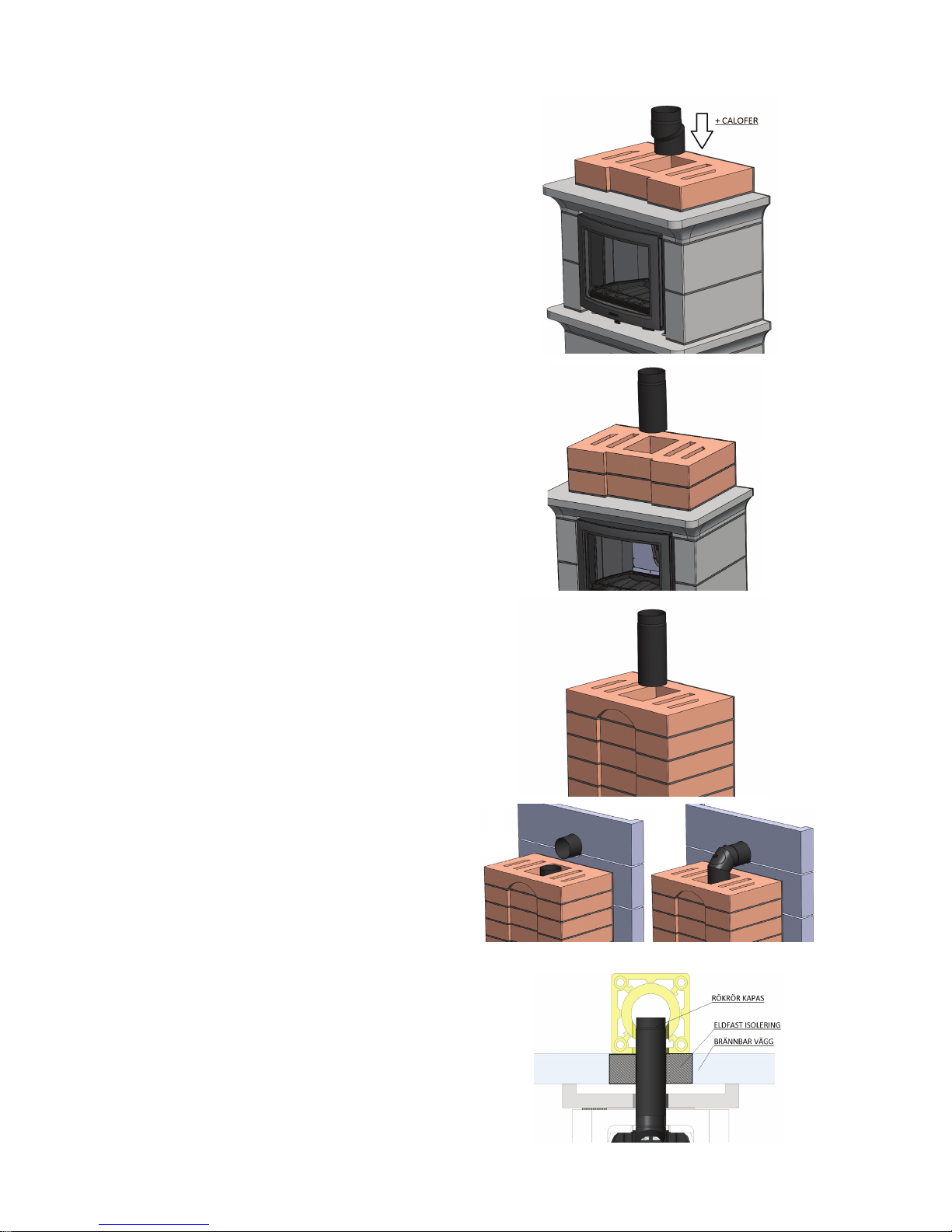
11. For rear connection. Cut the 500 mm pipe to a
suitable length. Hang the pipe in the hole prepared
in the chimney breast. After this, t the 90-degree
pipe on to the 390 mm pipe. Finish by sliding the
pipe in the wall with the 90-degree pipe.
NOTE! Rear connection through a flammable
wall.
If the ue is to be run through a ammable wall, the
connection pipe must be enclosed by a re-resistant, lined shaft (Masterboard, Minerit or similar) and
reproof insulation that is at least 100 mm thick.
Thus, there must not be any ammable material
closer than 100 mm from the ue.
If the outer diameter of the ue is ∅153 mm, the
shaft must be at least 353 mm x 353 mm.
For top connection of the stove, jump forwards to
point 13.
- 8 -

12. Install elements no. 7B, 8B and 9B in mortar.
Secure the connection sleeve with insulation in the
hole on the front. Let the connection sleeve protrude
an equal distance to the thickness of the rendering
(approx. 10 mm)
Test t the hot air grilles. NOTE! The grilles must
not be cemented into place, they should be
loose. Otherwise, there is a risk that cracks may
form
The cleaning cover and the hot air grilles are permanently installed after the stove has been rendered
and painted.
K20 Top connection cont.
13. Assemble elements 7 and 8 in mortar. Secure the
connection sleeve with insulation in the hole on the
front. Let the connection sleeve protrude an equal
distance to the thickness of the rendering (approx. 10
mm)
Test t the hot air grilles. NOTE! The grilles must
not be cemented into place, they should be
loose. Otherwise, there is a risk that cracks may
form
The cleaning cover and the hot air grilles are permanently installed after the stove has been rendered
and painted.
14. Install the 500 mm long pipe. Then, assemble
element no. 9 in mortar. Make sure that the insulation
is completely sealed between the pipe and element
9. The pipe must protrude approx. 50 mm above element no 9.
15. Install the hearth plates in the number order
shown in the illustration. Finish by installing the log
guard.
The stove is now ready for rendering. In connection with rendering, all grilles, cleaning covers and
frames for wall installation must be tted to prevent the dried rendering mortar from obstructing the
nal assembly. TIP! In connection with tting, it is best to carefully press in grates, cleaning covers and
frames for wall installation a few millimetres into the wet mortar. In this way, these parts are slightly recessed into the rendering when the stove has dried and you nally install these parts.
Once the rendering is completed, the stove must dry for a week. After this time, you can re with care on
three to four evenings (two to three res per evening). After this, you can paint the stove. Suitable paints
are water based wall paints.
- 9 -
Insulation
Sleeve protru-
CARE & FIRING INSTRUCTIONS
The Keddy K20 has been tested by a certified testing institute. It has extremely good environmental values and a useful efficiency exceeding 80%. For the stove to work optimally, it is
of key importance that you follow the care and firing instructions below. Non-compliance will
invalidate the warranty.
FUEL
The K20 must to be red with rewood. Most types
of rewood can be used. The most suitable are birch,
beech, ash, and elm, but conifers and oak can also
be used if they are mixed 50/50 with another type of
hardwood. Oak contains acids, which may aect the
stove and chimney during combustion.
The rewood must be dry, i.e. with a maximum
moisture content of 20%. If the rewood is moist, an
unnecessary amount of energy is used boiling the
water away before it starts burning normally. This
also forms large amounts of soot and tar, which are
deposited on the walls of the hearth and chimney,
which in turn signicantly increases the risk of a
chimney re.
Moist rewood also results in poor combustion, which
leads to greater smoke generation with sooty glass
and deterioration of the local environment as a consequence.
To be certain you will have dry wood when the heating season begins, it must be cut in the winter. The
wood is then stored in a ventilated place under a roof
and left to dry during the spring and summer. Before
using the wood, you should keep it indoors for a couple of days so there is time for the surface moisture
to evaporate.
WARNING! It is absolutely forbidden to re the stove
with painted, glued (e.g. Hardboard or chipboard) or
pressure-impregnated wood. It is also forbidden to
burn plastic and other waste in the insert. The combustion of such fuels and substances releases acids
and heavy metals, which are very harmful for both
people and the environment.
BEFORE FIRING - WHEN THE STOVE IS NEW
During the rst week, ring can be started carefully.
Start with one to two res during the rst couple of
days.
A particular smell will occur during the rst rings in
the stove. This is the cast iron's paint and rust proofing hardening. Ventilate as required and ensure that
there is good air exchange. The smell will normally
disappear after a few res.
FIRING
When you optimise ring manually, you should measure the amount of burned wood per hour. The stove
is not intended for an output exceeding 10 kWh, i.e.
never exceed the maximum amount of recommended
wood per hour. This not only impairs the eciency,
there is also a risk of overheating the insert and chimney. Suitable rewood sizes and quantities for the K20
are:
Kindling:
Length approx. 25-35 cm
Diameter approx. 2-5 cm
Split logs:
Length approx. 25-35 cm
Diameter approx. 6-10 cm
Quantity ca 2.0 kg /
load/hour
Max. quantity 3.0 kg / hour
NOTE! Every load should burn down completely
before you add new rewood. In which case, the
stove works at its best and you avoid the inconvenience of possible blow back.
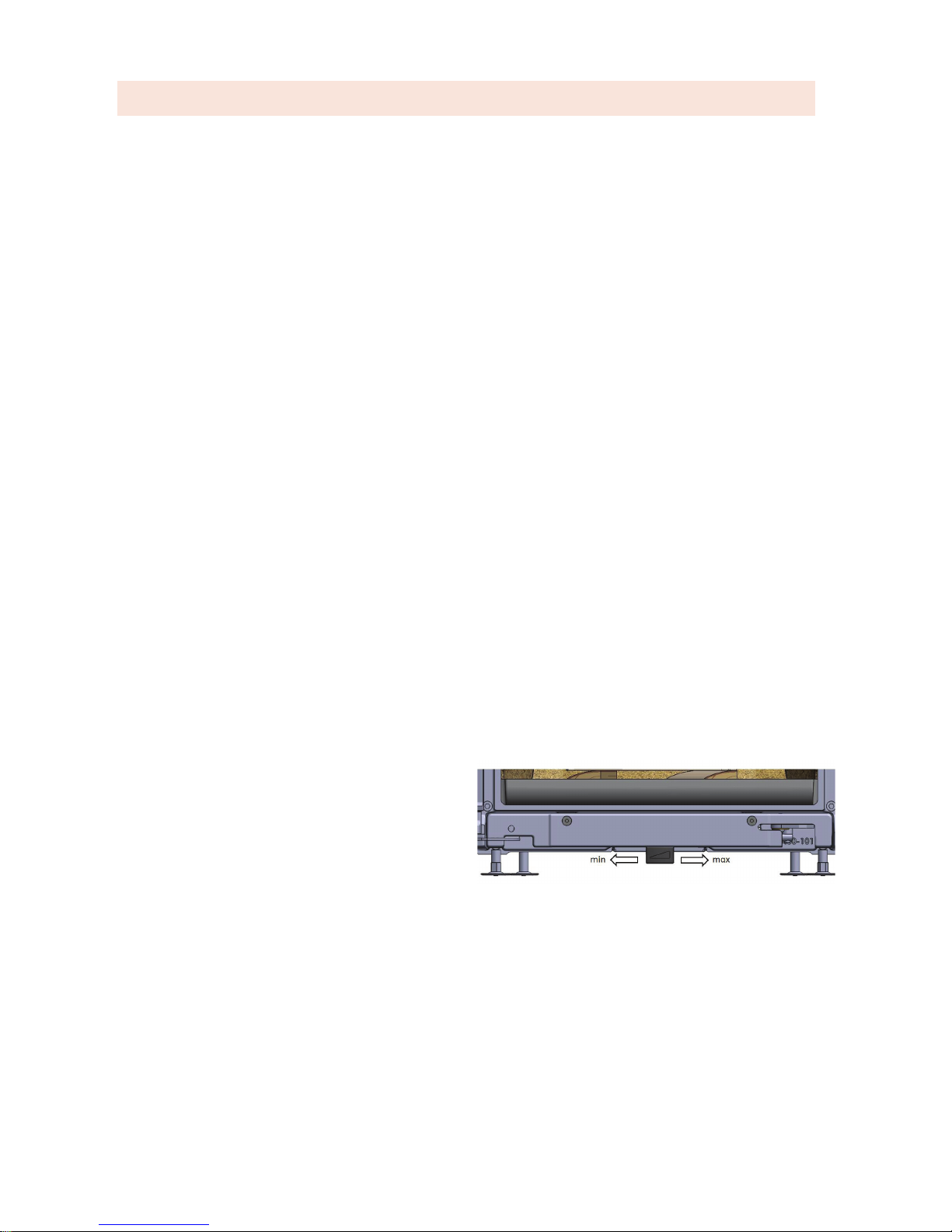
The damper is closed completely when it is turned to
the left and is open to the maximum when it is turned
to the right (see the illustration below).
The amount of air needed for burning for example 2
kg of wood in one hour depends on several parameters. The length of, and the draught in your chimney,
how hot the stove and chimney are, i.e. how long you
have red. The basic principle, however, is that the
stove has to burn calmly and harmoniously and, for a
hot stove, the damper control does not usually exceed
30-40% in order to achieve this at an output of 5-7
kW. (The damper control stands at 50% in the illustration above.)
As a rule of thumb, if you want to reduce the output, a
load of 2.0 kg rewood should burn for about 60 minutes. The stove will then provide approx. 5 kW.
- 10 -

Lighting a fire
1. Open the door by pulling on the xed handle under
the edge of the door. Then, lay kindling across this
until you have a total quantity of rewood of approx.
2.0 kg. (Approx. 15-20 pieces of kindling) (See picture below)
2. Push the damper control as far to the right as it will
go, place a couple of relighters on top of the heap
and light. In the majority of cases, you can close the
hatch immediately after lighting.
(If the chimney is cold or if there are unfavourable weather conditions, you may need to keep
the door ajar during the first couple of minutes
in order to establish a satisfactory chimney
draught.)
3. Let the rst re burn down with maximum air supply. This is to allow the stove to reach its operating
temperature quickly. Light a new re of the desired
size and close the door. Wait a couple of minutes,
until the re has started burning properly. Then turn
the damper to the left, until you have achieved a calm
and harmonious re.
Note! The reason why we want to achieve the optimum operating temperature in the stove quickly
is that it works with the best efficiency at this
temperature. This minimises the emissions and
maximises the heat generation.
The K20 is equipped with an innovative self-closing and self-locking door. When putting firewood
in or removing ash, carefully place the door at
90 to 95 degrees opening angle, so the door will
stay open. Give the door a light push, back past
the 90 degrees position, and the door closes
automatically and locks.
NOTE! For further information on firing in our
stove, see the film "firing tips" on keddy.se.
CARE & FIRING INSTRUCTIONS Cont...
GOOD TO KNOW
Since it can take some time for a cold chimney to
start working properly, i.e. to force the smoke in the
right direction, you can place a relighter on the bafe and light it. In this way, you eliminate the downdraught and avoid the nuisance of smoke entering
the room in the initial stage.
If the premises are equipped with mechanical ventilation, i.e. if there are one or more fans to evacuate
the air from the building, there may be such a large
negative pressure in the building that it could be difcult to light the stove. We suggest that you turn o
the ventilation temporarily or open a window until the
negative pressure has dissipated.
Firing with too coarsely chopped wood or with too
little oxygen supply, so-called smoulder combustion,
can be risky. In part, this increases the amount of
soot and tar due to poor combustion, which could
cause a chimney re. It could also lead to small gas
explosions, which may damage the insert. In addition
to this, the smoke from the chimney will be unhealthy
and cause inconvenience to your neighbours.
REMOVAL OF SOOT AND MAINTENANCE
Soot must be removed at least once per season. The
soot from the chimney and the connections should be
removed by a chimney sweep. The vermiculite bae
should be removed during soot removal.
If the glass becomes sooty, it is best to use a special
soot remover, which you can buy from your local
stove dealer. Never use detergents containing abrasive materials. This will damage the glass.
When emptying the stove, the ash should be placed
in a sheet metal container. Pay attention to the risk
of fire when you throw out the ash, as the ash
may contain live embers for a very long time!
IMPORTANT! If there is a chimney re, the stove
door and the supply air control must be closed. If
necessary, call the re brigade. After a chimney re,
the chimney must be inspected and approved by a
certied chimney sweep before the stove can be put
into use again.
PACKAGING
The stove is delivered on an untreated wooden pallet, which can be sorted as combustible material or
burned in the insert. Other packaging is corrugated
paper or paperboard, which should be sorted and
disposed of in the intended container at your nearest
recycling centre.
- 11 -
Rev 1, 01/07/2015
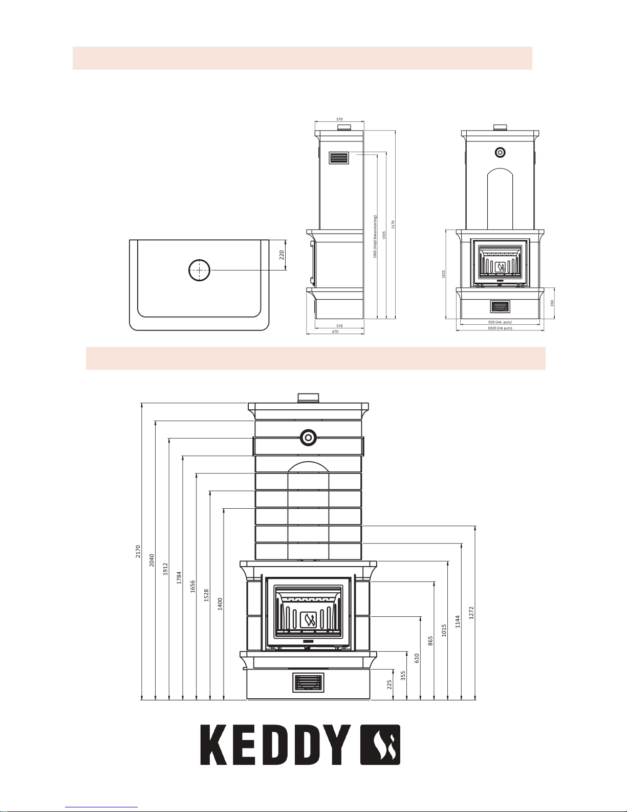
DIMENSIONS
K20 TECHNICAL SPECIFICATION
DIMENSIONS AND PERFORMANCE
Height 2170 mm
Width 920/1020 mm
Depth 570 mm
Weight K20 850 Kg
Height, centre rear connection 1905 mm
Height, top connection 2170 mm
Outer dimensions, connection ∅150 mm
Eciency 83 %
Nominal output 7 kW
Output 5-10 kW
 Loading...