


KEDACOM
User Manual for HD IP Camera of
LC Series
Version 01

Trademark
Kedacom™ and are trademarks of Suzhou Keda Technology Co., Ltd. in
China and various other count r ies. All other trademarks mentioned in this document are
the property of their respect ive holders.
Suzhou Keda Tec hnology Co., Ltd.
131 Jinshan Road
New District, Suzhou, 215011
People's Republic of China
http://www.kedacom.com/en
Tel: +86-512-68418188
Fax: +86-512-68412699
© 2014 Suzhou Ke da Technology Co., Ltd. All rights reserved.
Without the prior written per m ission of Suzhou Keda Technology Co., Ltd., any
reproduction, translat ion o r r et r ansm ission of all or any part of this document for any
purpose in either electroni c or me chanical form is not allowed.
Notice
The information in this docu ment i s subject to change without notice. Every effort has
been made in the preparat ion o f t his do cument to ensure accuracy of the contents, but all
statements, information, and recommendations in this document do not constitute a
warranty of any kind, express or i mp l ied. Suzhou Keda Technology Co., Ltd. is not
responsible for printing or clerical errors.

Target Audience
Administrators and Operators of Video Surveillance Product s
Document Version
Version 01
Applicable Models
LC2150 series, LC2250 s er ies, LC2110 series, LC2210 series, LC211 se ries, and
LC2240 series
Related Document
Quick Start Guide for LC2110 & LC2210
Quick Start Guide for LC2150 & LC2250
Quick Start Guide for LC211 LC 2240
Convention
Icon
Convention
Notes
italic
Book or document name;
Filling content
>
Connector between menus of different level
BOLD
Menu; Button; Option

Contents
1. Product Brief ................................................................................................................................... 1
1.1
Appearance .......................................................................................................................... 1
1.2 Main Functions ..................................................................................................................... 2
2.
Start Up ............................................................................................................................................ 3
2.1
Client Installation Conditions ................................................................................................ 3
2.2 Initial Configuration .............................................................................................................. 3
3.
Product Functions .......................................................................................................................... 6
3.1
Live View .............................................................................................................................. 6
3.1.1 Toolbar Buttons on Main Menu .................................................................................... 6
3.1.2
Image Adjustment ........................................................................................................ 7
3.2 Motion Detection ................................................................................................................ 10
3.2.1 Set Area ..................................................................................................................... 10
3.2.2
Clear Area .................................................................................................................. 11
3.2.3 Disable Function ........................................................................................................ 11
3.3 Privacy Mask ...................................................................................................................... 11
3.3.1
Set Area ..................................................................................................................... 11
3.3.2 Clear Area .................................................................................................................. 11
3.3.3 Disable Function ........................................................................................................ 11
3.4
Clipping Area Encode ........................................................................................................ 11
3.5 ROI Encode ....................................................................................................................... 12
3.6 *Snapshot .......................................................................................................................... 12
3.7
*Recording ......................................................................................................................... 12
3.7.1 Playback .................................................................................................................... 13
3.7.2 Download ................................................................................................................... 13
3.8
Upgrade ............................................................................................................................. 13

3.8.1
Firmware Upgrade ..................................................................................................... 13
3.8.2
IPCCtrl Upgrade ........................................................................................................ 14
4.
Parameter ...................................................................................................................................... 15
4.1
Network Access ................................................................................................................. 15
4.1.1
Ethernet ..................................................................................................................... 15
4.1.2 PPPoE ....................................................................................................................... 15
4.2 Register to VMS ................................................................................................................. 15
4.3
*BNC Output ...................................................................................................................... 16
4.4 User Management .............................................................................................................. 17
4.5 Text Overlay ....................................................................................................................... 17
4.6
Camera Mode .................................................................................................................... 18
4.6.1 Configure Parameter ................................................................................................. 18
4.6.2 Import/Export Configuration ....................................................................................... 19
4.7
Dual-Stream ....................................................................................................................... 19
5.
Appendix: Glossary of Terms ...................................................................................................... 21

HD IP Camera User Manual
1
1. Product Brief
HD IP Camera (her einafter r ef erred to a s Ca mera) is a re mot e video sur veill ance dev ice ba sed on IP
network technologyofinde pen d ent resear ch and dev elo pment of Suzhou Keda Technology Co., Ltd.
It encodes and trans mitsHD video. Also, itcan be deployed at any point of a sur veillan ce net w ork and
transmits videos via public or private IP network. The device has built-in IR illumination mod ule,
which satisfies different video surveillance requirements better.
1.1 Appearance
Picture1-1 LC2110/LC2210 Series
Picture1-2 LC2150/LC2250 Series
Picture1-3 LC211/LC2240 Series
Note: -B series without end bracket

HD IP Camera User Manual
2
1.2 Main Functions
Live View
Apply high-performance progressive scan sensor, with clear image and vivid color;
High-performance video processing chip and efficient video encoding, providing HD video;
Dual-stream to fit different network bandwidth;
Configurable text overlay on video
IRIllumination
Built-in IR illumination module to better satisfy different video surveillance requirements
Networking
Static address, DHCP or PPPoE;
NAT traversal, DNS and multicast technology
P
OE
PoE supported, realize network transmission and power supply only with a PoE switch
Camera Parameter Adjustable
Multiple camera parameters are adjustable to suit various surveillance requirements.
Motion Detection
User can set motion detection area in the surveillance scene. Once someone appears in the
defined area, the system will trigger alarm.
Privacy Mask
Keep sensitive information private.
ROI Encode
Only encode specific area to ensure normal surveillance and con stant resolut ion of key area
under poor network.
Clipping Area Encode
Only encode specific area to ensure normal surveillance of key area under poor network.
User Management
Different permissions will be allocated to different accounts to ensure normal operation of
device.

3
2. Start Up
Please refer to the Quick Start Guide in the packing for device installation and wiring.
2.1 Client Installation Conditions
Requirements of PC for installing the client:
Operating System: Windows XP or newer versions
Browser: IE6.0 or newer versions
Processor: 2.0 GHz CORE®2 series or other equivalent processors
RAM Memory: 2GB or above
DirectX:9.0c
2.2 Initial Configuration
1) Power on the camera after installing and wiring.
2) Get IPCSearch from the attached CD.
Note: IPCSearch is green software free from installation.
3) RunIPCSearch: it will search devices in LAN automatically and display the list as
shown in Picture 2-1.
Picture2-1IPCSearch
4) Select a camera to be configured, click or right click the mouse.
Interface is shown in Picture 2-2.

4
Picture2-2Modify Parameter
5) After modification, will be disabled and the device will reboot
automatically. Please wait patiently. After reboot, the button will be enabled again.
Please select this device again and click or double click device name to
enter web client. Interface is shown in Picture 2-3.
Picture2-3IPCCtrl Login Interface
6) Enter user name and password:
IPCCtrlaccounts consist of bothadmin and guest users:
admin: can perform full operations.
guest: can perform operations, for example, live video view, image search, video
record search, video playback, etc. guest can neit her conf igu re parameters, delete
videos or snapshots, nor operate user management or equipment maintenance.

5
7) Interface after login is shown in Picture 2-4.
Picture2-4IPCCtrl Interface
6
3. Product Functions
IPCCtrl can not only view live video, but also perform local snapshot and recording.
Note: Functions of different cameras may differ, and this Manual will take camera with more functions as
example. User operation is subject to the actual functions of the model. Disabled button in IPCCtrl
means the model doesn’t support the function.
3.1 Live View
The default interface after user login is live video v iew , or u se r can cl ic k L iv e View to enter the
interface.
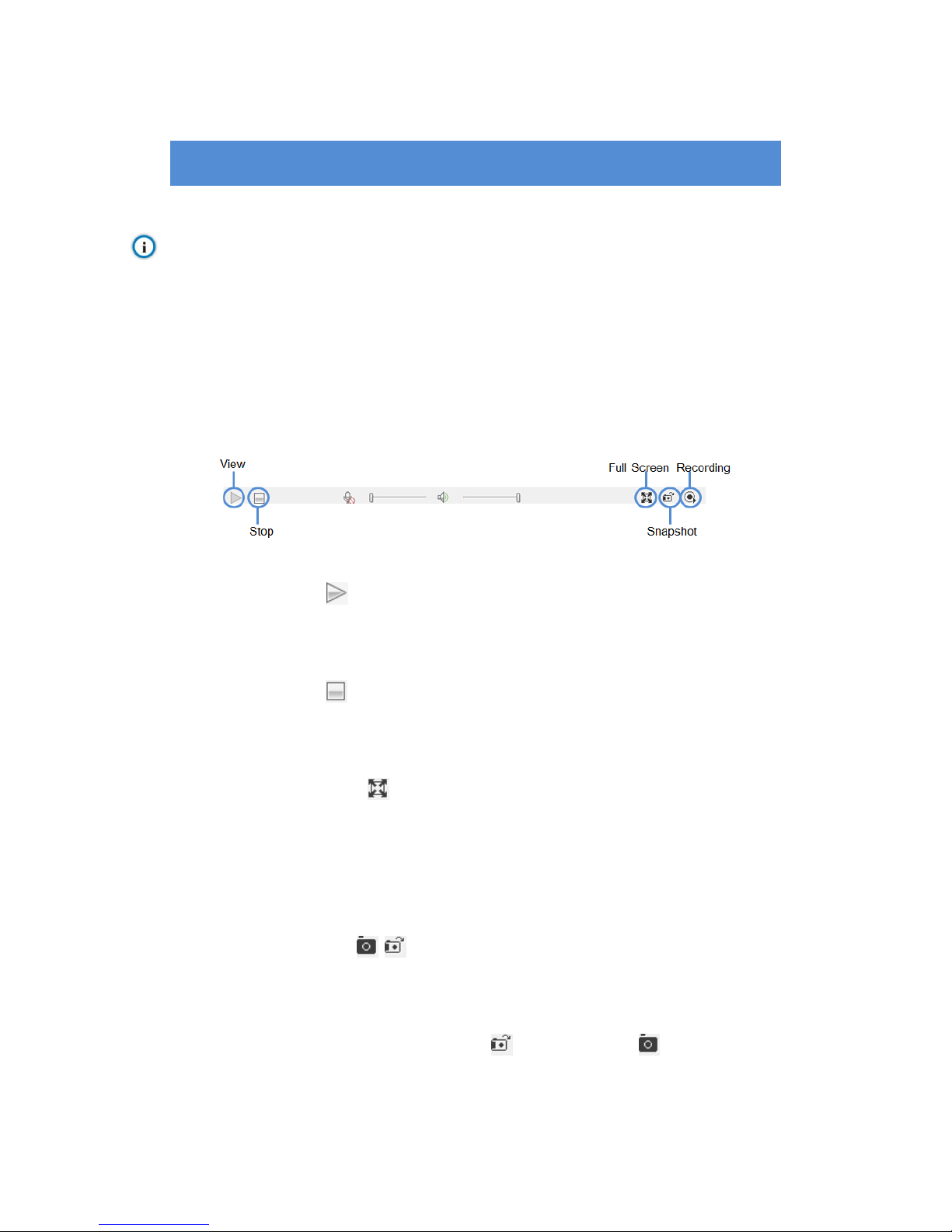
3.1.1 Toolbar Buttons on Main Menu
Picture3-1Toolbar Buttons on Main Menu
View
Click this button to play live video.
Stop
Click this button to stop live view.
Full Screen
Click this button to display full screen.
When Drag to Zoom is disabled, double click the live video to display full screen
directly, and double click again to exit.
Snapshot /
Click this button to snapshoot an image.
Snapshot includes PU Snapshot and Local Snapshot . User can set in
Parameter>Local Settin g.

7
Notes:
1) PU Snapshot: PU Snapshots an image and sends it to local client in .JPG format. The image
quality is good, but there is some time delay caused by network.
2) Local Snapshot: Client snapshots an image and save it locally. The image quality is ordinary,
but there isn’t any time delay.
Picture3-2Snapshot Setting
User can set or modify save path for PU Snapshot and Local Snapshot in
Parameter>Local Settin g, as shown in Picture 3-2.
Recording
Click this button to start recording and click again to stop recording. Recording is
saved on local PC. User can set or modify save path in Parameter>Local Setting.
3.1.2 Image Adjustment
3.1.2.1 Brightness
Due to low light situation, the image will look completely or partially dark and
hard to recognize. IPCCtrl provides the following functions to increase image
brightness and ensure surveillance quality.
Enable IR Lamp
In low light situation, IR lamp can be started to get better surveillance images.
Increase Image Brightne
SS

8
In Image Adjustment part, user can drag Brightness slide bar to adjust image
brightness.
Or, enable Camera Mode to make camera transfer to preset value in a defined
period of time.
Slower Shutter Speed
Camera shutter speed means the cycle of the sensor calculating light input
amount. Therefore, the slower the speed is, the brighter the image is.
Note: If the target object is moving fast, this met hod is not ap plicable.
Set Max. Auto Shutter and Min. Auto Shutter in Parameter>Video Parameter>Basic Setting.
Click (Manual) on Page 2 of function buttons to select shutter speed,
measured in second (s).
Increase Gain
Camera gain means the light sensitivity of a sensor. A high gain may reduce
light exposure for low light situation.
Note: However, the higher the gain is, the worse the image will be. User is advised to select Auto, applying
default values, or set Max. Auto Gain (range 6-42 dB) in Parameter>Video Parameter>Basic Setting
Enable
WDR
WDR can provide optimal exposure in intense backligh t con ditio ns.
On Page 2 of function buttons, click to enable WDR and to
disable WDR.
3.1.2.2 White Balance Adjustment
The basic conception of White Balance is “to make all colors white regardless
of the color temperature of the light source”. It can com pensate color rendition
in pictures taken in specific light source.
On Page 2 of function buttons, select White Balance Mode, Auto, Light or
Manual.
After selecting Manual, enter Red Gain and Blue Gain respectively to adjust
image colors.

9
3.1.2.3 Day/Night Mode
Day (Night) Mode means disabling (enabling) IR lamp, and the image shifts to
color (B/W), thus to get optimal images for day (sufficient light source) and
night (insufficient light source) cond itio ns.
Note: When a device without IR lamp enables Night Mode means the image shifts to B/W.
Day Mode
On Page 1 of function buttons, click (Day Mode) to disable IR lamp and
the image shifts to color.
Night Mode
Click (Night Mode) to enable IR lamp and the image shifts to B/W.
Auto
Click (Auto) and the system will shift Day/Night Mode automatically
according topre-set value. Notes for different devices are as follows:
Camera with IR lamp will shift to Day Mode or Night Mode automatically
according to IR Sensitivity, which can be set on Page 4 of function buttons.
Camera without IR lamp will shift to Day Mode or Night Mode automatically
according to Color to B/W value and B/W to Color value, which can be set on
Page 6 of function buttons.
Also, user can enable Camera Mode to make camera shift to Night Mode
automatically in a defined period of time.
3.1.2.4 Noise Reduction
When there are many noise points caused by environment and camera lens,
Noise Reduction function can be enabled to adjust images.
On Page 6 of function buttons, set Noise Reduction value and click to
save setting.
3.1.2.5 Auto Adjustment
Auto Adjustment applies default settings of the camera block, which are
suitable for most conditions.
On Page 1 of function buttons, click (All auto adjustments), and all
parameters will restore to default values.

10
Also, user can set Focus, Shutter and other parameter as Auto alone.
3.1.2.6 Video Freeze
On Page 5 of function but ton s, select t hi s functi on and t he vid eo w ill disp lay th e
last frame image before clicking. Click to disable freeze.
3.1.2.7 Drag to Zoom
Definition: Drag to Zoom function centers the selected area and zooms in the
area to full screen.
Enable:Right click the image and click Drag to Zoom on the popup menu to
enable the function; or check Drag to Zoom on the bottom of Page 1 of
function buttons.
Start:Drag an area (left to right) with mouse t o zoom in and center it.
Cancel:
Drag a reverse rectangle ( ri ght to left) with mouse to cancel zoom and
center.
Disable: Right click the image and click Drag to Zoom on the popup menu to
disable the function; or uncheck Drag to Zoom on the bottom of Page 1 of
function buttons.
Picture3-3Drag to Zoom
3.2 Motion Detection
Detect movements in the defined area. Once the movement exceeds the defined sensitivity,
an alarm will be triggered by IPCCtrl.
3.2.1 Set Area
Motion detection of Full Area and maximum 4 user-defined ar eas

11
1) Check Parameter>Video Parameter>Intelligent Alarm to set motion detection area.
2) Check En abl e Int e lli gent Alarm, and select Motion Detection. Detect ion area can be
full area or specific area. If user selects specific area, the user should define
detection area on the below image.
3) Click a squareand it will turn purple red. Start from this square and draw an area to
be the detection area, which will turn purple red.
4) Click under the view window or click to reset the area.
3.2.2 Clear Area
Start from an undefined square and draw an area that contains the defined area, or
click the defined squares one by one to clear setting. Save to make settings
effective.
3.2.3 Disable Function
To disable this function, uncheck the checkbox Enable Intelligent Alarm.
3.3 Privacy Mask
Mask sensitive and private part of the image so as to keep sensitive information private.
3.3.1 Set Area
The image is divided into 16 columns and 12 rows of small squares. The maximum
masking area can be 24 squares. The maximum number of Privacy Mask area is
4.
1) Check Parameter>Video Parameter>Privacy Mask to set privacy mask area.
2) Check Enable Privacy Mask.
3) Click a square and it will turn purple red. Start from this square and draw an area to
be the masking area, which will turn purple red.
4) Click under the view window or click to reset the area.
3.3.2 Clear Area
Start from an undefined square and draw an area that contains the defined area, or
click the defined squares one by one to clear setting. Save to make settings
effective.
3.3.3 Disable Function
To disable this function, uncheck the checkbox Enable Privacy Mask.
3.4 Clipping Area Encode
After user defines the encoding area, the system will encode and display the clipping area
only, so as to save system resources and network bandwidth.

12
In the interface Parameter>Video Parameter>Clipping Area Encode, drag an area with
mouse, click under the view window or click to reset the area.
3.5 ROI Encode
Only encode specific area to ensure normal surveillance and constant resolution of key area
under poor network. The resolution of the area must be greater than 704×576 and less than
the current resolution.
In the interface Parameter>Video Parameter>ROI Encode, drag an area with mouse, click
under the view window or click to reset the area.
Note: When ROI Encode is enabled, if user modifies image resolution or aspect ratio (stand
screen/widescreen), the device will quit ROI Encode automatically.
3.6 *Snapshot
Click to enter snapshot management interface. User can perform operations on
snapshots in SD card, such as view, delete and download.
Note: If the Snapshot interface is disabled, please confirm the SD card is inserted and then reboot client.
Operation Steps
1) Search snapshots: search those pictures within the defined duration from the SD
card.
2) On the snapshot list, select searched picture and perform operations such as view,
delete and download.
3.7 *Recording
Click to enter recording management interface. User can perform operations on
recordings in SD card, such as playback, delete and download. (A SD card must be inserted
in the camera.)
Note: If the Recording interface is disabled, please confirm the SD card is inserted and then reboot client.
Note: Record Mode includes:S tart Recordi ng When Disconnected, Recording All the Time, and Stop
Recording, configurable in Parameter>Recording Parameter.

13
Picture3-4Recording
3.7.1 Playback
1) Select Recording Duration from Calendar.
2) If there is background color on a date, it means there is recording on that day.
Select duration of the date and the video will be displayed directly in the right
window.
3.7.2 Download
Select Recording Duration from calendar and download recording to local PC,
download path configurable.
3.8 Upgrade
3.8.1 Firmware Upgrade
Contact dealer for upgrade file.
Method1
1) Enter IPCCtrl interface Parameter>System Maintenance> Upgrade, as shown in
Picture 3-5.

14
Picture3-5Firmware Upgrade
2) Select local upgrade file (<*.pkg> or <*.img> format).
3) During upgrading, please do nothing but waiting.
4) After upgrading, please download ActiveX control again. After finishing it, reboot
browser.
Note: Please click “Upgrade” during system upgrading, and the upgrade file is usually in <*.pkg> or <*.img>
format.
Method2
1) RunIPCSearch.
2) Click to upgrade firmware of cameras of the same model
simultaneously.
3.8.2 IPCCtrlUpgrade
After firmware upgrade, please login web client again. The page will prompt to
download a new ActiveX control. After downloading it, client upgrade will be
completed. Login again to enter the latest IPCCtrl.
Note: For detailed operation instructions of IPCCtrl, please refer to the help document.

15
4. Parameter
4.1 Network Access
2.2 Initial Configuration has introduced how to modify parameters via IPCSearch to make
camera access network. Cam era ac cept s m ulti ple n etwork access methods (via Ethernet and
PPPoE). The following introduces how to configure camera network parameters in IPCCtrl.
4.1.1 Ethernet
Open Parameter>Network Setting>Ethernet Parameter, as shown in Picture 4-1 to
configure IP address, subnet mask and default gateway.
Picture4-1Ethernet Parameter
4.1.2 PPPoE
Open Parameter>Network Setting>PPP
OEParameter, as shown in Picture 4-2 to
enter user name and password, and save.
Picture4-2PPPoE Parameter
4.2 Register to VMS
OpenParameter>System Setting>Register to VMS as shown in Picture 4-3 to enter VMS
address and port. Save settings and reboot device.

16
Picture4-3Register to VMS
4.3 *BNC Output
Camera with BNC output can output analog image directly when local display function is
enabled.
Open Parameter>Video Parameter>C amera Parameter, select ‘Start’ from the BNC Output
drop-down list and set the CVBS Video Mode, as shown below.
Picture4-4BNC Output

17
4.4 User Management
Admin user has the authorization to modify passwords of IPCCtrl admin user and guest user.
Modification method:
1) Open Parameter>System Setting>User Management
2) Check the chec kbox of the item to be modified, the password area will be
enabled and editable.
3) Enter new password.
4) Confirm new password.
5) Click Save to validate setting, and Reset to quit modification.
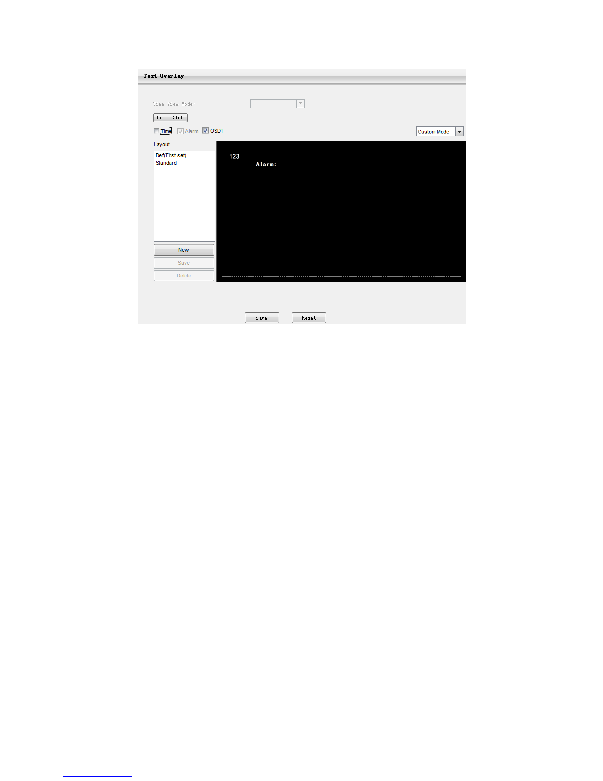
4.5 Text Overlay
Display preset text on the surveillance window, configuration steps as follows:
1) Open Parameter>Video Parameter>Text Overlay
2) Check Edit Text checkbox, as Picture 4-5 shows.
3) User ca n creat e and s ave mu ltiple OS D layout s. Cl ick Creat e and in put lay out nam e.
Select this layout from the list and edit it.
4) Check text types to be overlaid, time and user-defined OSD selectable.
Note: Different models may support different numbers of OSD. Configuration is subject to actual camera
model.
5) Double cl ic k user-defined OSD to input text content. Each OSD supports maximally
3 lines of text. User can check Align Right checkbox to align texts on the right, or
the default setting is “align left”.
6) Drag text to the ideal position in the view window.
7) Click Save to validate settings, and Reset to quit edit.
18
Picture4-5Text Overlay
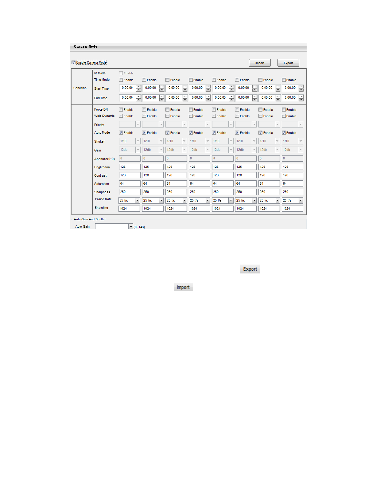
4.6 Camera Mode
Open path: Parameter>Video P arame ter>Camera Mode
After enabling Camera Mode, user can define maximally 8 different non-overlapping
durations, and all parameters will be adjusted to the preset values automatically.
4.6.1 Configure Parameter
4.6.1.1 Night Mode
After enabling this function, device will shift toNight Mode in the defined
duration automatically. The IR lamp will be enabled and the image will turn
B/W.
4.6.1.2 Shu tter, Gain, Auto
Shutter and Gain values configurable
Or enable Auto mode to apply set Shutter and Gain automatically.
4.6.1.3 Brightness, Contrast, Saturation, Sharpness
Brightness, Contrast, Saturation and Sharpness values configurabl e
Brightness, Contrast, Saturation and Sharpness range: 0-255.
4.6.1.4 Frame Rate, Encoding Rate
Frame Rate and Encoding Rate configurable
19
Picture4-6Camera Mode
4.6.2 Import/Export Configuration
After completing configuration of camer a mode, cl ic k to export and save
the configuration; click to import local configuration file instead of
manual configuration.
4.7 Dual-Stream
Camera supports dual-stream encodin g. Dua l-stream means the same video source is
encoded in 2 strea ms of video w ith different r esolut ions. U ser can s elect d iffere nt resolu tion to
view or record according to the bandwidth conditions.
Open Parameter>Video Parameter>Main Stream Encode, as shown in Pictu re 4-7 to check
Enable Sec. Stream checkbox. After enabling , user can conf i gure sec ondary str ea m
parameters in Parameter>Video Parameter>Secondary Stream Encode.

20
Picture4-7Main Stream Encoding
Note: For detailed operation instructions of the client IPCCtrl, please refer to the help document.

5. Appendix: Glossar y of Terms
Term Explanation
720P
Resolution of 1280*720 pixels
CIF
Resolution of 352*288 pixels
QCIF
Resolution of 176*144 pixels
PU
Periphery Unit, such as camera and encoder used for
video surveillance
ROI
Region Of Interest
Key Frame
Interval
Key Frame defines the important frame when change
happens in a video. This frame will be completely
encoded. Key Frame I nterv al defines the maximum frames
during the interval between key frames. If the video
changes
quite frequently, shorter Key Frame Interval will
make video more real, but it will take more bandwidth.
Quantization
Set Min. and Max. Quantization,and image compression
quantization will fluctuate in the range.
During image compression, larger
quantization brings
higher compression ratio and higher distortion ratio. On
the contrary, smaller quantization brings lower
compression ratio and better image recovery
, but
meanwhile takes more bandwidth.
 Loading...