


DIGITAL READY TV
WWW.KEC.CO.KR
MODEL: 29GG400
INSTRUCTION MANUAL

FEATURES
640 480 Resolution !
Flickerless picture and NTSC image conversion to progressive scan!
You can view an analog broadcasts with the best picture quality .
Receive digital broadcasts by connecting with a ATSC set-top box!
High-performance adaptive 4H comb filters and vertical peaking create vivid pictures ever for the sub display window.
Motion adaptive spatial and temporal noise reduction(3D-NR) reduces a lot of noise
in the picture!
Scan velocity modulation circuit improves the contour between black and white pictures!
ABC Circuit(Automatic Brightness Control) always enables you to see the best picture regardless of the surrounding brightness conditions.
A digital sound processor.
Sound output power equal to a mini component.
BTSC(MTS M) Stereo signal decoder!
Spatial surround effect for a spectacular listening experience!
Loudness effect a grand bass sound.
AVC(Automatic Volume Correction) equalizes varying sound volume levels.
Independent volume and source control for headphones!
EXCELLENT SOUND QUALITY
EXCELLENT PICTURE QUALITY
3
EXCELLENT PICTURE AND SOUND QUALITY, MULTIPLE FUNCTION
READY TELEVISION FOR DIGITAL BROADCASTING
TABLE OF CONTENTS
FEATURES 3~5
PRECAUTIONS
6~8
LOCATION OF CONTROLS
9~10
USE OF THE REMOTE CONTROLLER
11~12
ANTENNA CONNECTION
13~14
POWER SUPPLY
15
VIDEO / AUDIO CONNECTION
16~18
STARTING OPERATION
19
PICTURE ADJUSTMENT
20~21
SOUND ADJUSTMENT
22~25
CLOCK SETTING
26~28
SETUP
29~31
PICTURE-IN-PICTURE OPERATION
32~35
FUNCTION
36~38
DOUBLE WINDOW
39~42
COMPATIBILITY WITH PERSONAL COMPUTER
43~45
RECEIVING DIGITAL BROADCASTS
46
V-CHIP FUNCTION
47~56
SLEEP FUNCTION
57
DISPLAY FUNCTION
57
QUICK VIEW FUNCTION
57
MUTE FUNCTION
57
RECEPTION DISTURBANCE
58
TROUBLE-SHOOTING GUIDE
59
PRODUCT SPECIFICATIONS
60
BEFORE USING THIS PRODUCT
MISCELLANEOUS
APPLICATION
PERFORMANCE

4
5
MISCELLANEOUS FUNCTIONSMISCELLANEOUS FUNCTIONS
Closed Caption Decoder : A Built-In Closed Caption Decoder(CCD) detects broadcasts
with encoded closed caption signals and displays their content on the screen.
Built-In V-Chip(Violence Chip) : This "Blocking V-Chip" Allows adults to block television
programs, movies, and videos which they feel are inappropriate for children.
Power saving function : The power consumption in the stand-by state is below 3 watts!
DOUBLE WINDOW
PERSONAL
COMPUTER INPUT
WIDE
BOOSTER
TILT
CLOCK AND
TIMER
SLEEP
AUTOMATIC
POWER-OFF
DISPLAY
QUICK VIEW
PIP
CHANNEL INDEX
STROBE
Watch main and sub picture simultaneously!
It can display a 640
480 VGA PC signal!
Watch TV at wide display state.
When the antenna input signal is weak, booster amplifies the
power of signal!
compensates for the picture display for tilting to either the left or
right because of the geomagnetic effects.
Set the time, minutes and then use like a clock and timer!
The television automatically turns off after the set sleep time.
Turned off automatically after 15 minutes in the absence of picture signal!
Display the channel number, picture and sound state, mts and
clock!
Switches the current channel to the previously viewed channel.
Two tuner PIP allows simultaneously display of VIDEO and TV,
TV and TV, 2 VIDEO sources.
Check other broadcasting pictures in sequence while watching
the main picture!
View the action frame by frame in still quick hots!

6
7
PRECAUTIONSPRECAUTIONS
Don’t open the rear cover.
This may expose you to very high voltages and other hazards.
Avoid changing the direction of the TV set in a state of
power-on, any color-blur may happen.
In such case, plug it off and plug it on after an hour.
Avoid places that has much moisture and dust.
Place TV set on a flat and stable spot.
Separate TV set from magnetic materials like speaker, telephone.
Take due care not to use this TV close to other electric apparatus.
Select an area where sunlight or bright indoor illumination
will not fall directly on the picture screen.
Keep TV set away from an iron.
Don’t place heavy objects on the TV.
Don’t cover air holes with a towel or any materials.
When there is thunder and lightning or when you don't watch
for a long time, pull the power plug out.
Don’t pull the power cord out.
Don’t use a volatile solvents like benzene in cleaning.
Clean TV with a piece of dry cloth.

8
LOCATION OF CONTROLS
9
PRECAUTIONS
FRONT PANEL VIEW(LIST OF KEY SWITCHES, CONNECTORS)GRAPHICAL SYMBOLS EXPLANATION
This lightning flash with arrowhead symbol, within an
equilateral triangle is intended to alert the user to the
presence of uninsulated "dangerous voltage" within
the product's enclosure that may be of sufficient magnitude to constitute a risk of electric shock to persons.
The exclamation point within an equilateral triangle is
intended to alert the user to the presence of important
operating and maintenance (Servicing) instructions in
the literature accompanying the appliance.
CAUTION
RISK OF ELECTRIC SHOCK
DO NOT OPEN.
CAUTION : TO REDUCE THE RISK OF
ELECTRIC SHOCK, DO NOT
REMOVE COVER (OR BACK)
NO PARTS INSIDE.
REFER SERVICING TO
QUALIFIED SERVICE PERSONNEL.
123456789101112 13 14 15
1. ABC Sensor
2. Headphone Terminal
3. R Sound Input Terminal(3)
4. L Sound Input Terminal(3) : MONO
5. Video Input Terminal(3)
6. S-VHS Input Terminal(3)
7. Channel Down(
) Button
8. Channel Up(
) Button
9. Volume Down(
) Button
10.Volume Up(
) Button
11. Menu Button
12. TV/Video Button
13. Remote Controller Sensor
14. Stand-by Indicator
15. Power Button

THE USE OF THE REMOTE CONTROLLERLOCATION OF CONTROLS
10
11
REAR PANEL VIEW
Point to the remote controller sensor of the TV set.
The maximum operatable distance is approximately 20 feet from the remote controller
sensor, and not more than 30
to either side of the center.
The operation of the remote controller is most effective when there's no obstruction
between it and the remote controller sensor.
The duration of the batteries is approximately 6 months to 1 year.
Replace the batteries when the remote operation becomes unstable.
BATTERY INSTALLATION
Open up the cover.
Correctly install the batteries, observing (+/-) polarity as shown in the compartment.
Do not use a combination of old and new batteries or different type of batteries.
If batteries become weak, remove and replace them soon.
When battery leakage occurs, clean the battery compartment with a soft cloth and
replace the batteries.
2R
G
B
2 RGB IN
2
ANT
PC IN
2
2R
G
B
2 RGB IN
2
ANT
PC IN
2
123456789
1. Antenna Input(75 ohm)
2. Video/Audio Output Terminals
3. Video/Audio Input Terminals(1)
4. Video/Audio Input Terminals(2)
5. S-VHS Input Jack(2)
6. Component Video Input Terminals(DVD IN)
7. Audio Input Jacks(In Case of DVD, RGB, PC Mode)
8. R, G, B Input Terminals
9. Personal Computer Input Terminal
(D-Sub Connector)

ANTENNA CONNECTION
THE FUNCTIONS OF THE REMOTE CONTROLLER
12
13
1. P.C Mode Selection Button
2. Video Mode Selection Button
(VIDEO1
VIDEO2 VIDEO3 YUV RGB TV)
3. Power Button
4. Surround Button
5. Double Window Button
6. Mute Button
7. Quick View Button
8. Channel Up(
) / Down( ) Button
9. Volume Up(
) / Down( ) Button
10. Menu Button
11. Sleep Button
12. Wide Display Button
13. Sound Standard Button
14. Picture Standard Button
15. 10 Digit Keys
16. CATV 100 Channel Selection Key
17. State Display Button
18. Channel Add/Delete Button
19. Mono
Stereo SAP Selection Button
20. Picture State Control Button
21. Automatic Brightness Control Button
22. PIP On/Off Button
23. PIP TV VIDEO1 VIDEO2 VIDEO3 YUV
RGB Selection Button
24. PIP Position Selection Button
25. PIP Window Size Selection Button
26. Main
Sub Window Swap Button
27. PIP Channel Up(
) and Down(
) Button
28. V-CHIP Button
29. PIP Channel Index Button
30. PIP Strobe Button
31. PIP Still Button
POWER
VIDEO
DOUBLE
MUTE
SLEEP
WIDE
P.STD
DISPLAY
ABCPICTUREMTSADD/DEL
POSITION
V-CHIP STILL INDEX
STROBE
SIZE SWAP CH
TV/VIDEO
S.STD
Q.VIEW
MENU
VOL
CH
CH
VOL
P.C
SURROUND
1234
5678
90
100
PIP
2
3
1
4
6
10
9
11
13
18
19
16
22
24
31
25
28
5
7
8
12
14
15
17
21
20
27
26
23
30
29
A. Combination VHF/UHF Antennas
B. Separated VHF/UHF Antennas
VHF ANTENNA UHF ANTENNA
300-ohm
twin-lead
300-ohm
twin-lead
75-ohm
coaxial cable
ANT/
CABLE
75Ω
IN OUT
COMBINER
(not supplied)
REAR OF TV
or
VHF/UHF ANTENNA
300/75-ohm
ADAPTER
(Not supplied)
300-ohm
twin-lead
75-ohm coaxial cable
ANT/
CABLE
75Ω
or
VHF/UHF ANTENNA
REAR OF TV
OUTDOOR ANTENNA CONNECTION
Use one of the following two diagrams if you connect an outdoor antenna.
A. Using a VHF/UHF combination outdoor antenna.
B. Using separate VHF AND/OR UHF outdoor antenna.
Connect an outdoor antenna cable LEAD-IN to the coaxial cable connector on the rear
of the TV set.
15
ANTENNA CONNECTION
14
POWER SUPPLY
220V INPUT 110V INPUT
INSERT 110V ADAPTER INTO AC POWER PLUG.
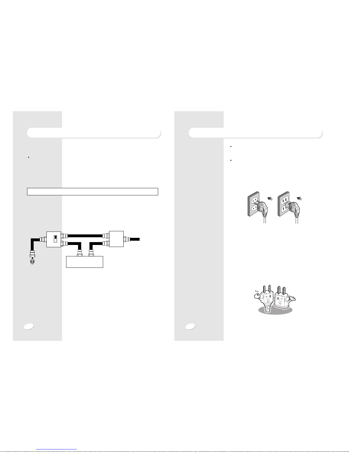
Cable TV line
TV
OUT IN
Cable TV converter/
descrambler
Two-set
signal
splitter
(not supplied)
RF switch (not supplied)
A
OUT IN
B
"A" position on the RF switch (not supplied)
:You can view all unscrambled channels using the TV's channel keys.
"B" position on the RF switch (not supplied)
:You can view the scrambled channels via the converter/descrambler using the con-
verter's channel keys.
NOTE : An RF switch equipped with position A/B (not provided) is required.
CABLE TV(CATV) CONNECTION
Some cable TV companies offer premium pay channels.
Since the signals of these premium pay channels are scrambled, a cable TV converter /
descrambler is generally provided to the subscriber by the cable TV company. This converter / descrambler is necessary for normal watching of the scrambled channels.
In case that the power cord is 110V AC, Insert the AC cord
plug into a standard 110V polarized AC outlet.
In case that the type of power cord is like as shown below,
insert the AC cord plug into the AC outlet. The input power
supply of this television is automatically regulated.
It is designed for convenient use in any 110V/220V power
source without switching an input voltage selector.

17
16
VIDEO /AUDIO CONNECTION
1. A/V OUT : Connect this A/V output terminals to another monitor input.
2. A/V 1 IN : Push the video button in sequence until VIDEO 1 appears on the picture.
Source input for composite video and audio signal of VCR, LDP(Laser Disc Player) or
set-top box.
3. A/V 2 IN : Push the video button in sequence until VIDEO 2 appears on the picture.
Source input for composite video and audio signal of VCR, LDP(Laser Disc Player) or
set-top box.
2R
G
B
2 RGB IN
2
ANT
PC IN
2
75
COXIAL
CABLE
VIDEO /AUDIO CONNECTION
AUDIO
HEADPHONE
OR
EARPHONE
S-VHS
VIDEO
R-AUDIO-L VIDEO 3 IN S-VHS
(MONO)
VCR/VDP/LDP/CAMCORDER/DVD
GAME-PLAYER
15PIN D-SUB
CONNECTOR
15
610
11 15
Please use the front terminals(VIDEO 3) for a GAME-PLAYER or CAMCODER.
S-VHS Input has priority over VIDEO 3 input.
Push the video button in sequence until VIDEO 3 appears on the picture.
Listen to the sound of main picture or sub picture with headphone or earphone.
19
18
STARTING OPERATION
1. Push the power button on the front panel or on the remote controller.
If power plug is inserted into an AC outlet, the stand-by indicator will be red.
2. Select the channel you want to watch by CH
/ button or 10 digit keys.
Channels can be selected directly by using 10 digit keys.
For example, to select channel 5, press “0” first, then press “5”.
For channel 120 in CATV mode, press 100 button first, then press “2”, then “0”.
3. Adjust the volume of sound.
NOTE : Certain channels have been pre-set at the factory.
It may be necessary to add or delete some channels.
See “MENU / SETUP / ANTENNA / AUTOPROGRAM” on page 29 for adding
channels in memory.
VIDEO /AUDIO CONNECTION
4. S-VHS IN : At either video 2 or video 3 mode, insert S-VHS cable from set-top box or
VCR into S-VHS terminal.
And the display will change from video 2 to S-VHS 2 or video 3 to S-VHS 3.
S-VHS input has priority over video 2 input.
5. DVD IN : Insert A/V cables from DVD player. Be Careful in connecting the jacks for
Y,CB,CR.
6. L,R : In case of DVD, RGB or PC mode, input the audio signals into this L,R JACKS if
necessary.
7. RGB IN : Insert A/V cables from DVD player or set-top box.
8. PC IN : Connect personal computer to the TV set via a D-SUB connector.
Set PC with 640
480 mode.
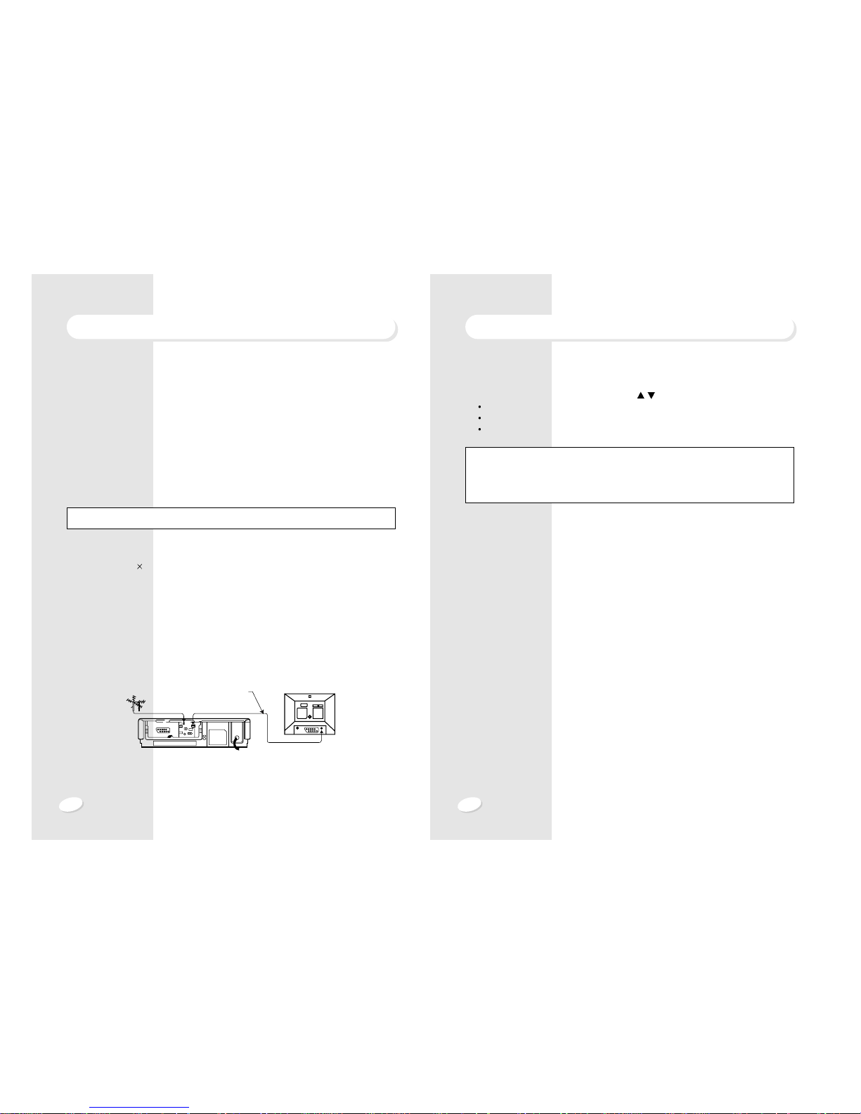
9. YOU CAN ALSO CONNECT A HOME VCR TO TV.
Connect the antenna lead-in cable from antenna to the RF IN socket of VCR.
and then connect the coaxial cable from the RF OUT socket of the VCR to the antenna
socket of TV set.
ANTENNA To "RF IN"
To antenna socket
To "RF OUT"
Coaxial cable
NOTE : The SYNC signal is on G SIGNAL and the input frequency is 15.734KHZ.
21
20
PICTURE ADJUSTMENT
MANUAL PICTURE ADJUSTMENT
Adjust the picture state one by one, using
VOL + and CH
/ button. Pressing
PICTURE button on the remote controller,
the same display will appear.
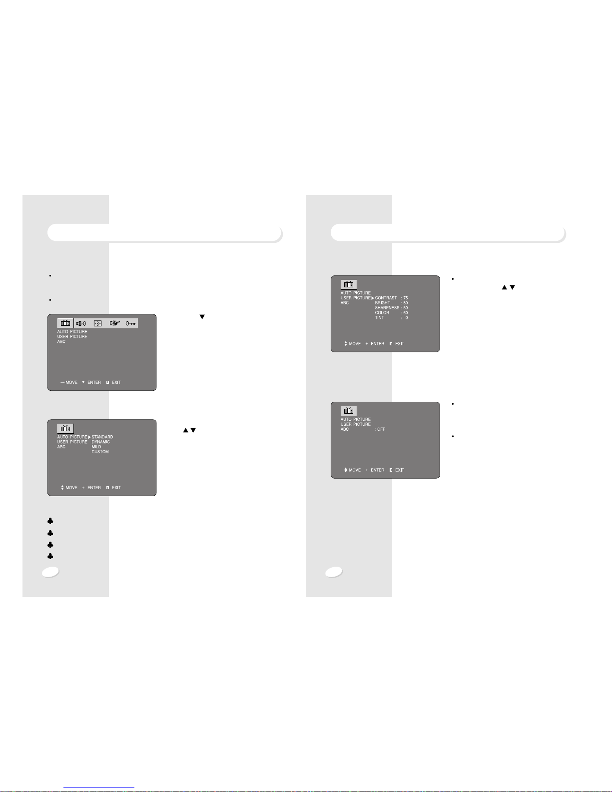
ABC(AUTOMATIC BRIGHTNESS AND CONTRAST CONTROL)
If you set ABC on, the brightness and contrast will automatically be adjusted to optimum levels according to the surroundings.
Pressing ABC button on the remote controller, the same function will operate.
PICTURE ADJUSTMENT
AUTOMATIC PICTURE ADJUSTMENT
By pressing the P.STD button on the remote controller, sequentially select any one of 4
picture standard pre-sets.
Press menu button and then select PICTURE icon by VOL -/+KEY.
1. Press CH
button
2. Select the picture state, using VOL + and
CH
/ button.
STANDARD : Select this mode to watch TV at standard state.
DYNAMIC : Select this mode to watch in a room with bright illumination.
MILD : Select this mode when the room is dark or to lessen eye fatigue.
CUSTOM : Select this mode to view the picture to your set picture state preference.
23
22
SOUND ADJUSTMENT
MANUAL SOUND ADJUSTMENT
Adjust the sound state one by one, using
VOL + and CH
/ button.
LOUDNESS :
Loudness effects for a grand bass sound.
AVC(
AUTOMATIC VOLUME CORRECTION
) :
different sound sources fairly do not have
the same volume level.
This result in annoying volume changes.
AVC solves this problem by equalizing the
volume levels.
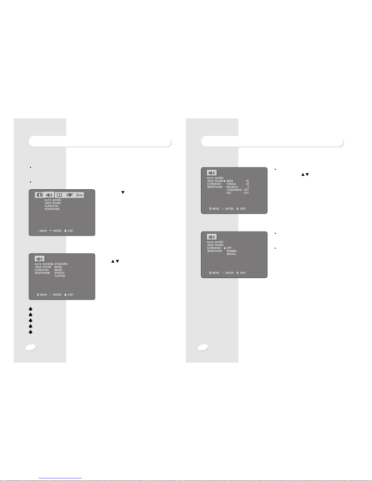
SURROUND EFFECTS
1. If the incoming signal is mono, pseudo stereo effects is active. So, normal mode is the
same amplitude and phase as spatial mode.
2. For stereo signal, stereo base width enlargement is effective. The spatial surround
effects provides a spectacular listening environment !
SOUND ADJUSTMENT
AUTOMATIC SOUND ADJUSTMENT
By pressing the S.STD button on the remote controller, sequentially select any one of 4
SOUND standard pre-sets.
Press menu button and then select SOUND icon by VOL -/+ Key.
1. Press CH
button
2. Adjust the Sound state, using VOL + and
CH
/ button.
STANDARD : Select this mode to listen to TV at standard state.
MUSIC : Select this mode to listen to music.
MOVIE : Select this mode when viewing a movie.
SPEECH : Select this mode to here voices clearly.
CUSTOM : Select this mode to listen to the sound at your set sound state prefer-
ence.

25
24
SOUND ADJUSTMENT
STEREO SOUND SYSTEM
When the power is switched on or channel changes, “ [[S]], ]” symbols are automatically displayed, depending on the current broadcast signal.
If the receiving signal is weak, noise may be heard.
In such case, press MTS button and set the sound mode mono for better sound reception.
SOUND ADJUSTMENT
HEADPHONE
Adjust the volume of sound by VOL + and
CH
/ button.
STEREO SOUND SYSTEM
This TV has a built-in BTSC system(Zenith
DBX System) decoder to receive stereo
broadcast and SAP(Secondary Audio
Program) such as a bilingual broadcast.
Whenever MTS button is pressed, the reception mode will change as below.
MONO
STEREO
SAP
The “ [[S]], ] ” symbols indicate that a broadcasting station is transmitting a multiplex
sound broadcast.
[[S]]
STEREO SYMBOL
] SAP SYMBOL

27
26
The On/Off timer lets you use alarm and automatic off-functions .
Set ON TIMER’S time and minutes, using
VOL+ and CH
/ button.
Set OFF TIMER’S time and minutes,
using VOL+ and CH
/ button.
If you have not yet set the television’s clock, the message “CLOCK STOPPED” will be
displayed when activating the timer.
The message “ON” appears to indicate that the timer function is already operating. And
notice the color of stand-by indicator becomes green.
CLOCK SETTINGCLOCK SETTING
Set the time and minutes and use as a clock and timer!
Set the current time before you set the automatic On/Off timer.
The current time will be displayed by pressing Display button on the remote controller.
Press menu button and then select CLOCK icon by VOL -/+ Key.
1. Press CH
button.
2. Set the current time and minutes,using
VOL + and CH
/ button.

29
28
ANTENNA SELECTION
CATV
TV
In this mode, you can change the broadcast mode between TV (For regular VHF/UHF
channel) and CATV (For cable channel).
Press menu button and select set-up icon by VOL -/+ Key.
1. Press CH
button.
2. Change the broadcast mode by VOL +
button.
SET UPCLOCK SETTING
When the power is off(stand-by mode)
after timer is set, the color of stand-by
indicator changes from green to orange.
If on timer and off timer is set at the same
time and minutes, ON TIMER has priority
over off timer when power is off
You can activate timer function and channel, using VOL + and CH
/ button.
SLEEP TIMER
Select a sleep time period from 15 to 90 minutes.
The television automatically is turned off after the set sleep time has elapsed.
Whenever sleep button is pressed, the time period change as shown below
OFF
15 30 45 60 90.
AUTOMATIC POWER -OFF OPERATION
Set is turned off automatically after 15 minutes in the absence of picture signal.
 Loading...