

Page 1

KeContact
P30 x-series
Charging station
Configuration manual V 4.00
Translation of the original instructions
Page 2

Document:V 4.00 / Article No.: 98412
Filename: P30x_confen.pdf
Pages: 38
© KEBA
Specifications are subject to change due to further technical developments. Details presented may be subject to correction.
All rights reserved.
KEBA AG Headquarters:
Gewerbepark Urfahr, 4041 Linz, Austria, Phone: +43 732 7090-0, Fax: +43 732 7309-10,
keba@keba.com
For information about our subsidiaries please look at www.keba.com.
Page 3

P30 x-series Table of contents
Configuration manual V4.00
3
© KEBA
Table of contents
1 Introduction ................................................................................................................
5
1.1 Purpose of the document.................................................................................
5
1.2 Requirements...................................................................................................
5
1.3 Intended use ....................................................................................................
6
1.4 Guarantee ........................................................................................................
6
1.5 Notes on this document ...................................................................................
7
1.5.1 Contents of the document..................................................................
7
1.5.2 Not contained in this document .........................................................
7
1.6 Further documentation.....................................................................................
7
2 Safety notes ................................................................................................................
9
2.1 Representation.................................................................................................
9
2.2 General safety instructions ..............................................................................
10
2.3 Safety information for personal safety .............................................................
11
3 System overview ........................................................................................................
12
3.1 Network interfaces ...........................................................................................
12
3.1.1 LAN....................................................................................................
13
3.1.2 WLAN ................................................................................................
13
3.1.3 WLAN Access Point (WLAN Hotspot) ...............................................
14
3.1.4 GSM...................................................................................................
15
3.2 Design of a local charging network (master/slave) ..........................................
16
3.2.1 Displays and signals ..........................................................................
17
3.2.2 Direct connection of master and slave...............................................
17
3.2.3 Connection via router or switch .........................................................
17
3.2.4 Ports for communication in the charging network..............................
19
4 Configuration..............................................................................................................
20
4.1 Connection panel .............................................................................................
20
4.2 DIP switch settings...........................................................................................
20
4.3 Configuration via web interface........................................................................
21
4.3.1 Main menu .........................................................................................
23
4.3.2 User menu .........................................................................................
25
4.4 Enabling the DHCP server...............................................................................
26
4.5 Configuration in series via USB stick ...............................................................
26
5 Functions ....................................................................................................................
28
5.1 Load management in the local charging network ............................................
28
Page 4

P30 x-seriesTable of contents
Configuration manual V4.00
4
© KEBA
5.1.1 Equal allocation mode .......................................................................
28
5.1.2 Current limiting...................................................................................
28
5.2 RFID authorization ...........................................................................................
28
5.2.1 Displays and signals ..........................................................................
29
5.2.2 RFID authorization without OCPP backend connection ....................
30
5.2.3 RFID authorization with OCPP backend connection .........................
30
5.2.4 Start charging procedure with RFID authorization.............................
31
5.3 OCPP backend ................................................................................................
31
5.4 UDP interface...................................................................................................
32
6 Diagnosis and troubleshooting ................................................................................
33
7 Maintenance................................................................................................................
34
7.1 Software update...............................................................................................
34
7.1.1 Software update via web interface.....................................................
35
7.1.2 Software update via USB stick (x-series only)...................................
35
Index ............................................................................................................................
36
Page 5
P30 x-series Introduction
Configuration manual V4.00
5
© KEBA
1 Introduction
Information
This document refers to the following software version:
From software version 1.5 and higher
Before configuring, check if the charging station is a P30 x-series with the
specified or a later version of the software.
The device variant can be determined by the product name on the nameplate. The software version can be read out via the web interface. For more
information, see the operating instructions.
1.1 Purpose of the document
This document describes the configuration of the P30 x-series charging station.
Information
This document is an extension to the supplied manuals of the P30 x-series
charging station. You must comply with all instructions and safety notes in
these manuals!
1.2 Requirements
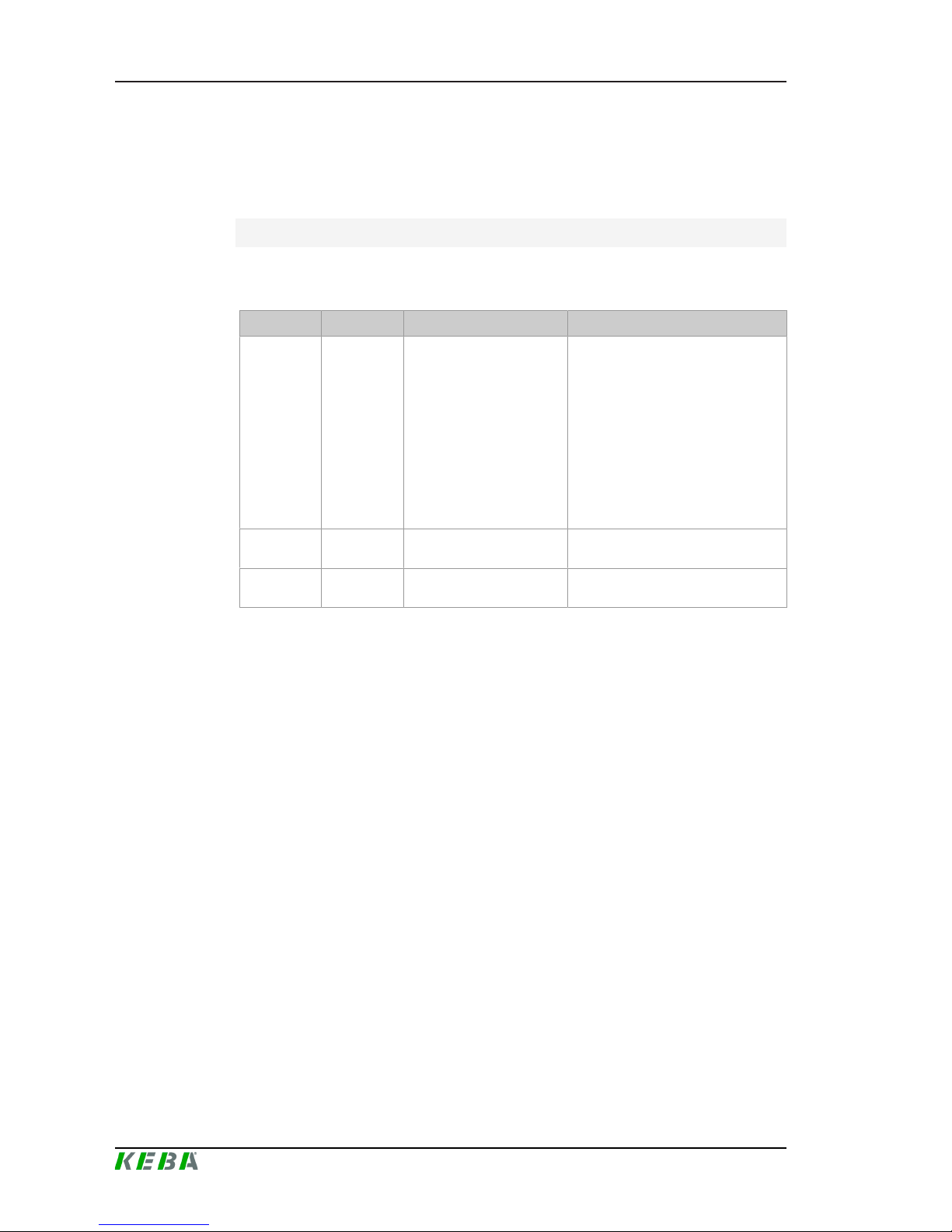
This document contains information for persons with the following requirements:
Target group Required knowledge and abilities
End customer
Knowledge of:
● the mode of operation of the charging station,
● the displays and operating elements of the charging station.
Start-up technician
Electrician with suitable basic technical basic education
Knowledge of:
● current valid safety information,
● the mode of operation of the charging station,
● the displays and operating elements of the charging station,
● basics of network technology,
● the troubleshooting,
● the setting options on the charging station.
Page 6

P30 x-seriesIntroduction
Configuration manual V4.00
6
© KEBA
Target group Required knowledge and abilities
Service technician
Electrician with suitable basic technical basic education
Knowledge of:
● current valid safety information,
● the mode of operation of the charging station,
● the displays and operating elements of the charging station,
● basics of network technology,
● diagnostic options,
● Systematic fault analysis and rectification,
● the setting options on the charging station.
Content that only addresses one target group is marked accordingly.
1.3 Intended use
The charging station is intended for charging electric vehicles. The connection of other devices (such as power tools) is not allowed.
The charging station is suitable for indoor and outdoor use. The charging
station has to be installed on a wall or in a floor-mounted column. The respective national regulations must be observed with regard to the installation
and connection of the charging station.
The intended use of the device always includes the compliance with the environmental conditions for which this device was developed.
The charging station has been developed, manufactured, tested and documented in accordance with the appropriate safety standards. If the instructions and safety instructions described for the intended use are observed,
the product will normally not pose a risk to the health of persons or damage
to property.
The instructions contained in this manual must be followed precisely. Failure
to do so could result in the creation of potential sources of danger or the disabling of safety devices. Apart from the safety instructions given in this manual, the safety precautions and accident prevention measures appropriate to
the situation in question must also be observed.
1.4 Guarantee
WARNING!
Only the maintenance work expressly permitted by KEBA may be performed. Any other manipulations to the device will also result in loss of warranty.
Page 7

P30 x-series Introduction
Configuration manual V4.00
7
© KEBA
Only the intended covers may be opened. If one of the covers is sealed by a
lead seal, it is not permitted to be opened by unauthorized persons. If the
lead seal is broken, the device loses its specific suitability and may no longer
be put into operation due to the resulting incorrect marking.
The front part (4 Torx screws) may not be opened. Opening the front part will
break the warranty seal and void the warranty. For a warranty claim, there is
a duty of proof of the customer that the defect – which led to the defect of
the device – already existed at the time of delivery. If the warranty seal is
broken, this proof can no longer be provided, whereby the warranty claim expires.
After an unauthorized opening of the charging station, product safety can no
longer be guaranteed. A device with broken warranty seals or removed lead
seals may no longer be put into operation. The necessary steps for replacement or repair of the charging station by the manufacturer must be initiated.
1.5 Notes on this document
The manual is part of the product. It is to be retained over the entire life cycle
of the product and should be forwarded to any subsequent owners or users
of the product.
1.5.1 Contents of the document
● P30 x-series Charging station
● Commissioning of the charging station
● Configuration of the charging station
1.5.2 Not contained in this document
● Disassembly of the charging station
● Operating behavior of the charging station
● Operation of the charging station
● Troubleshooting
1.6 Further documentation
Manuals and additional information can be found in the download area on
the KEBA website at
http://www.keba.com/de/emobility/service-support/downloads/downloads
available:
Page 8
P30 x-seriesIntroduction
Configuration manual V4.00
8
© KEBA
Designation Target group
User manual
● End customer
● Electrician
● Start-up technician
● Service technician
Installation manual
● Electrician
● Start-up technician
● Service technician
FAQ
● End customer
● Electrician
● Service technician
USB Configuration Guide
● Programmer
● Start-up technician
● Service technician
UDP Programmer's Guide ● Programmer
Page 9

P30 x-series Safety notes
Configuration manual V4.00
9
© KEBA
2 Safety notes
2.1 Representation
At various points in this manual, you will see notes and precautionary warnings regarding possible hazards. The symbols used have the following
meaning:
DANGER!
indicates an imminently hazardous situation, which will result in death or serious bodily injury if the corresponding precautions are not taken.
WARNING!
indicates a potentially hazardous situation, which can result in death or serious bodily injury if the corresponding precautions are not taken.
CAUTION!
means that if the corresponding safety measures are not taken, a potentially
hazardous situation can occur that may result in slight bodily injury.
Caution
means that damage to property can occur if the corresponding safety measures are not taken.
ESD
This symbol reminds you of the possible consequences of touching electrostatically sensitive components.
Safety information
Describes important safety-related requirements or informs about essential
safety-related coherences.
Information
Identifies practical tips and useful information. No information that warns
about potentially dangerous or harmful functions is contained.
Page 10

P30 x-seriesSafety notes
Configuration manual V4.00
10
© KEBA
2.2 General safety instructions
Caution
● The connection panel is never permitted to be left open unattended. Before leaving the charging station, the connection panel cover must be
mounted.
● A repair of the charging station is not permitted and may only be carried
out by the manufacturer.
● A damaged charging station must be switched off immediately and replaced.
● No unauthorized modifications and modifications may be made to the
charging station.
● No markings (such as safety signs, warnings, wire markings ...) may be
removed from the charging station.
● The charging station does not have its own power switch. The charging
station is de-energized via the circuit breaker of the building installation.
● Pull the charging cable out of the plug holder only by the plug and not by
the cable.
● No extension cords may be used.
● The charging cable may not be not damaged mechanically (kinked,
pinched or driven over) and the contact area is not allowed to come into
contact with sources of heat, dirt or water.
● Visually inspect for damage prior to charging. In particular, the following
must be checked:
Check the contact area of the charging plug for dirt and moisture, check
the charging cable for cuts or abrasions of the insulation, check the cable outlet or charging socket of the charging station for tightness.
Not observing the safety instructions can result in risk of death, injuries and
damage to the device! The device manufacturer assumes no liability for resulting claims!
Page 11
P30 x-series Safety notes
Configuration manual V4.00
11
© KEBA
2.3 Safety information for personal safety
WARNING!
Danger of personal injury due to electric shock!
Installation, commissioning, maintenance or retrofitting of the charging station must be performed by correctly trained, qualified and authorized electricians1) who are fully responsible for the compliance with existing standards
and installation regulations. For details, see the installation manual.
1)
Persons who, due to their special training, expertise and experience as
well as knowledge of current standards, are able to assess the work performed and the possible hazards.
Page 12
P30 x-seriesSystem overview
Configuration manual V4.00
12
© KEBA
3 System overview
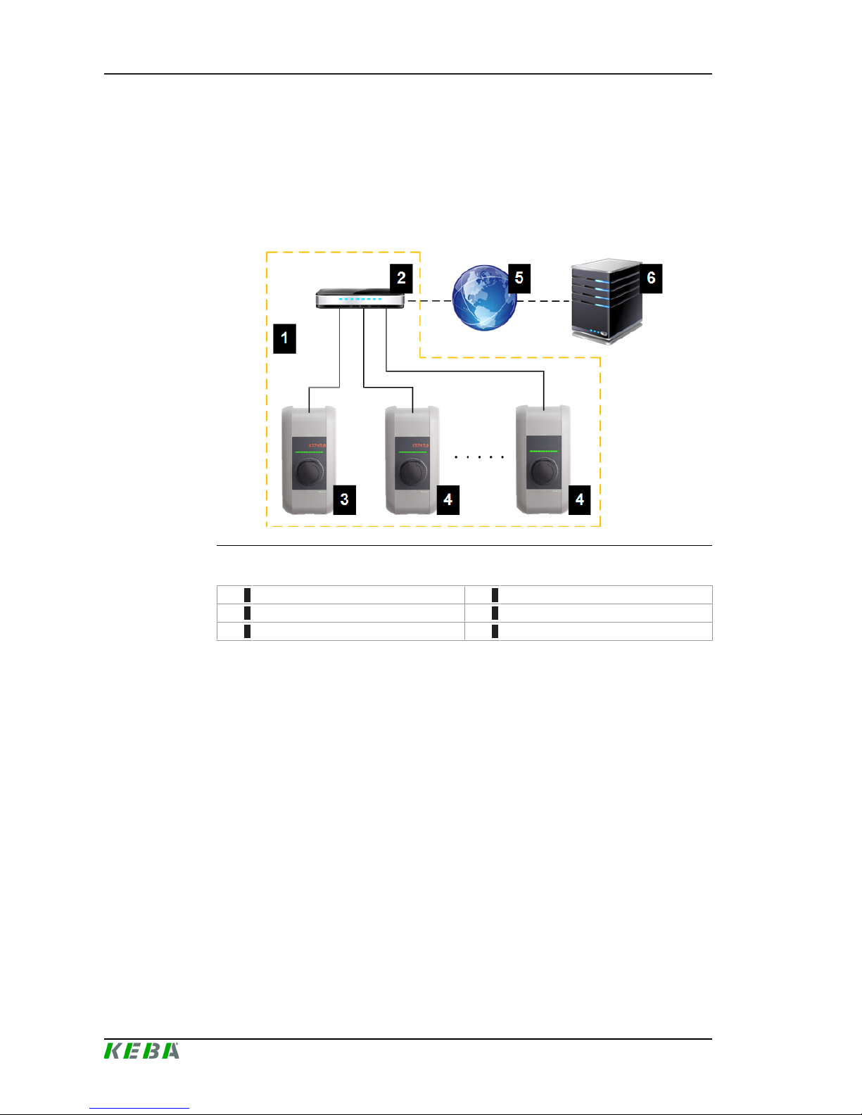
With the P30 x-series charging station, several charging stations can be interconnected and a master/slave network can be realized. This makes
charging with an intelligent load management possible. In addition, a connection to a higher-level OCPP backend can take place. The charging station is equipped with different network interfaces for these functions.
Illustration3-1: Example network setup
1 ... Local charging network 2 ... Router/Switch
3 ... Master charging station (x-series) 4 ... Slave charging station (c-series)
5 ... Internet 6 ... OCPP backend
Only P30 x-series can be operated as master charging stations; only P20/30
c-series can be operated as slave charging stations.
The following chapters describe which network interfaces the master charging station provides and how to set up a master/slave network.
3.1 Network interfaces
The master charging station provides the following network interfaces (e.g.
for connection to an OCPP backend, ...):
● LAN
● WLAN
● WLAN access point
● GSM (optional)
Slave charging stations can only be connected via LAN to a master charging
station.
Page 13

P30 x-series System overview
Configuration manual V4.00
13
© KEBA
3.1.1 LAN
The master charging station can be connected to a router via the integrated
LAN interface. The router provides a connection to an OCPP backend over
the Internet.
Connection: Ethernet1 connection (LSA+)
Via the LAN interface, the master charging station can also be connected to
other charging stations, whereby a charging network can be realized.
Information
The Ethernet2 connector [X3] (RJ45) is for debugging purposes only and
may not be used to connect to a network.
The Ethernet1 connector [X4] (LSA +) and the Ethernet2 connector [X3]
(RJ45) are connected in parallel on the PCB and can not be used at the
same time! The connection that is not used must be unplugged.
3.1.2 WLAN
The master charging station can be connected to a router via the integrated
WLAN interface. If the router is connected to the Internet, a connection to an
OCPP backend can be made.
Page 14

P30 x-seriesSystem overview
Configuration manual V4.00
14
© KEBA
The technical data of the WLAN module can be found in the "Installation
Manual".
3.1.3 WLAN Access Point (WLAN Hotspot)
The master charging station can be connected to a mobile device via the integrated WLAN access point (WLAN hotspot). With the mobile device, the
web interface can be easily accessed and the configuration of the charging
station can be performed.
The access data and the IP address of the WLAN access point are listed on
the configuration label. The configuration label is in a pouch affixed to the
manual set.
The following steps are necessary to perform the configuration via a mobile
device:
1) Connect a mobile device to the WLAN access point.
2) Access the IP address of the WLAN access point in a web browser on
the mobile device.
3) Perform configuration via the web interface, see 4.3 Configuration via
web interface.
Page 15

P30 x-series System overview
Configuration manual V4.00
15
© KEBA
3.1.4 GSM
Certain device variants have a GSM module. A master charging station with
GSM can connect to an OCPP backend over the cellular network. The mobile communications provider may charge additional fees (depending on the
tariff) for running data transmissions.
For the connection to an external OCPP backend via GSM, a SIM card must
be installed during commissioning. In addition, GSM must be activated as
connection to the OCPP backend and the access data of the mobile service
provider must be set in the configuration.
The technical data of the GSM interface and the SIM card can be found in
the "Installation Manual".
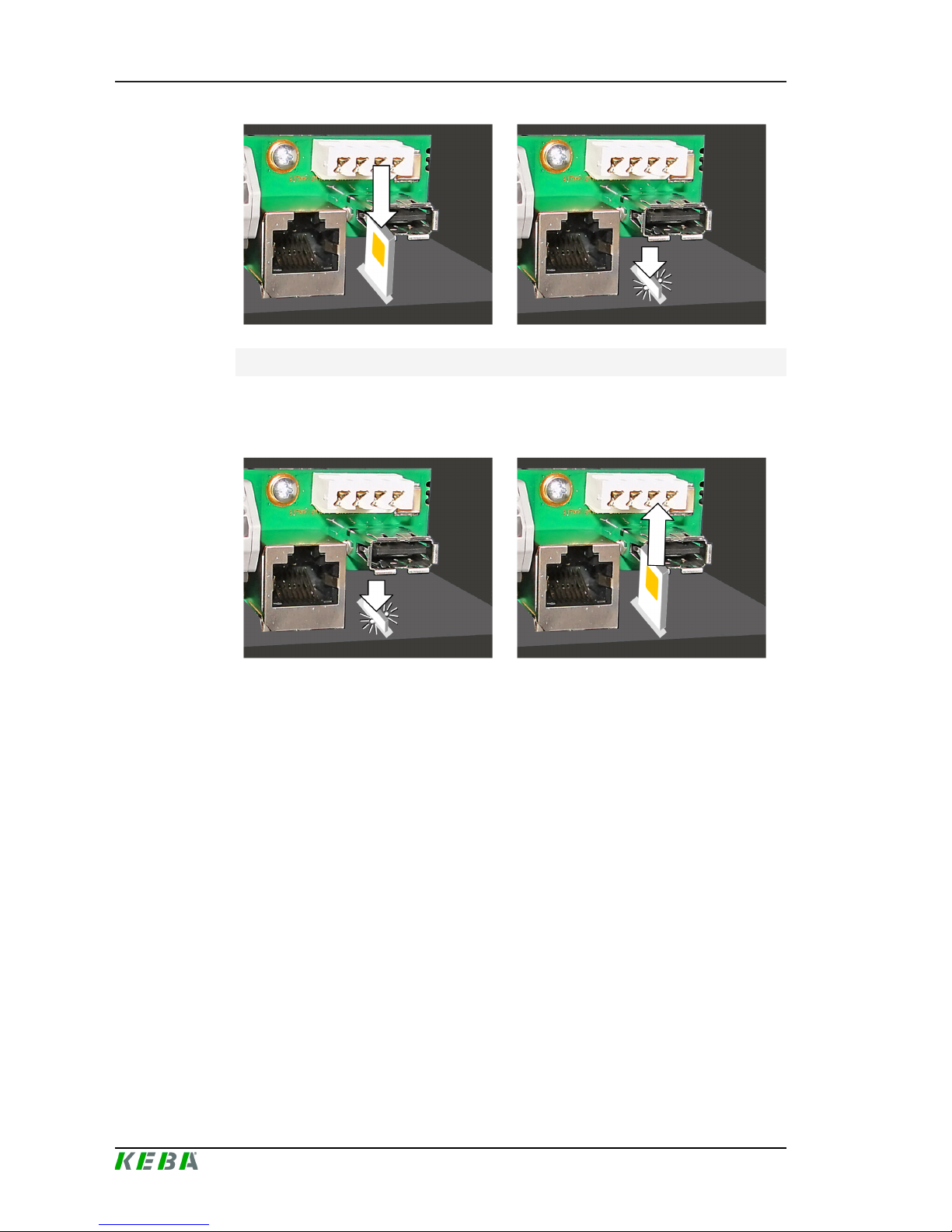
Preparing the GSM connection
The SIM card is inserted in the GSM module. The slot for the SIM card is located in the connection panel of the charging station. To access this button,
the housing cover and the connection panel cover must be removed.
Illustration3-2: Insertion slot
Inserting the SIM card
1) If still present, remove the indicated sticker above the SIM insertion slot.
2) Lightly press the SIM card into the slot until the spring mechanism locks.
Page 16
P30 x-seriesSystem overview
Configuration manual V4.00
16
© KEBA
Removing the SIM card
1) By lightly pressing the SIM card with your finger, the spring mechanism
is activated and the SIM card is ejected.
2) Remove the SIM card.
3.2 Design of a local charging network (master/slave)
A local charging network includes a P30 x-series as master and up to 15 cseries (P20 and/or P30) as slaves.
Depending on the number of slave charging stations, the design of a local
charging network is implemented differently:
● 1 slave charging station: Direct connection
The slave charging station is connected directly to the master charging
station.
● Multiple slave charging stations: Connection via router or switch
The slave charging stations are connected to the master charging station
via a router or switch.
To enable communication between master and slave charging stations, the
charging stations must be configured in the web interface, see 4 Configura-
tion.
Page 17
P30 x-series System overview
Configuration manual V4.00
17
© KEBA
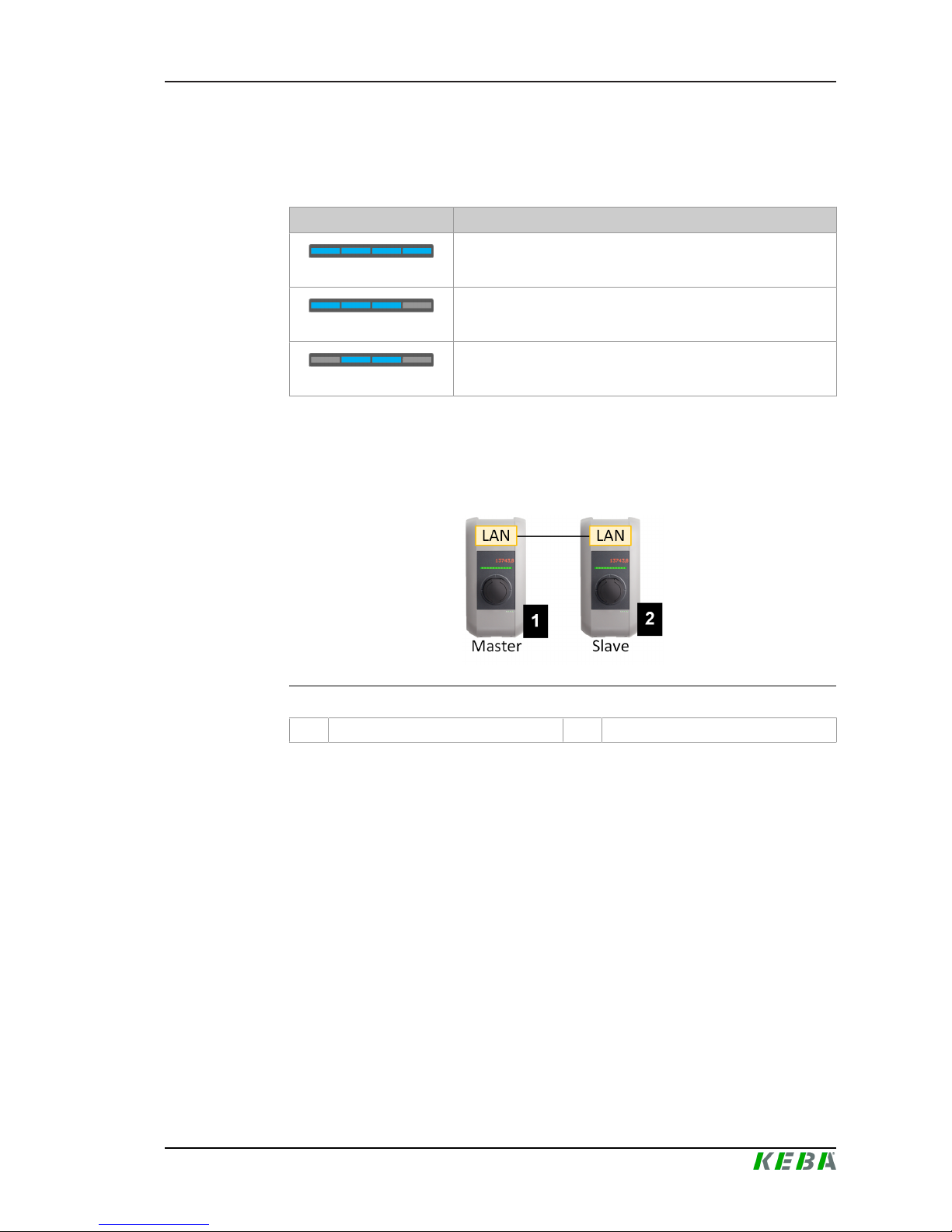
3.2.1 Displays and signals
The display on the front of the charging station provides information about
which communication connection is established.
Display Description
blue | blue | blue | blue
Communication is possible throughout the network.
The master charging station and the OCPP backend are reachable.
blue | blue | blue | -
Communication between master and slave charging stations is
possible.
The OCPP backend is not reachable or missing.
- | blue | blue | -
Communication between master and slave charging stations is
not possible.
The OCPP backend is not reachable.
3.2.2 Direct connection of master and slave
A single slave charging station can be connected directly to the master
charging station via LAN.
Illustration3-3: Direct connection of master and slave
1 P30 x-series (master) 2 P20/P30 c-series (slave)
In this case, the master charging station must be configured as a DHCP
server. The IP address is then assigned to the slave charging station by the
master charging station.
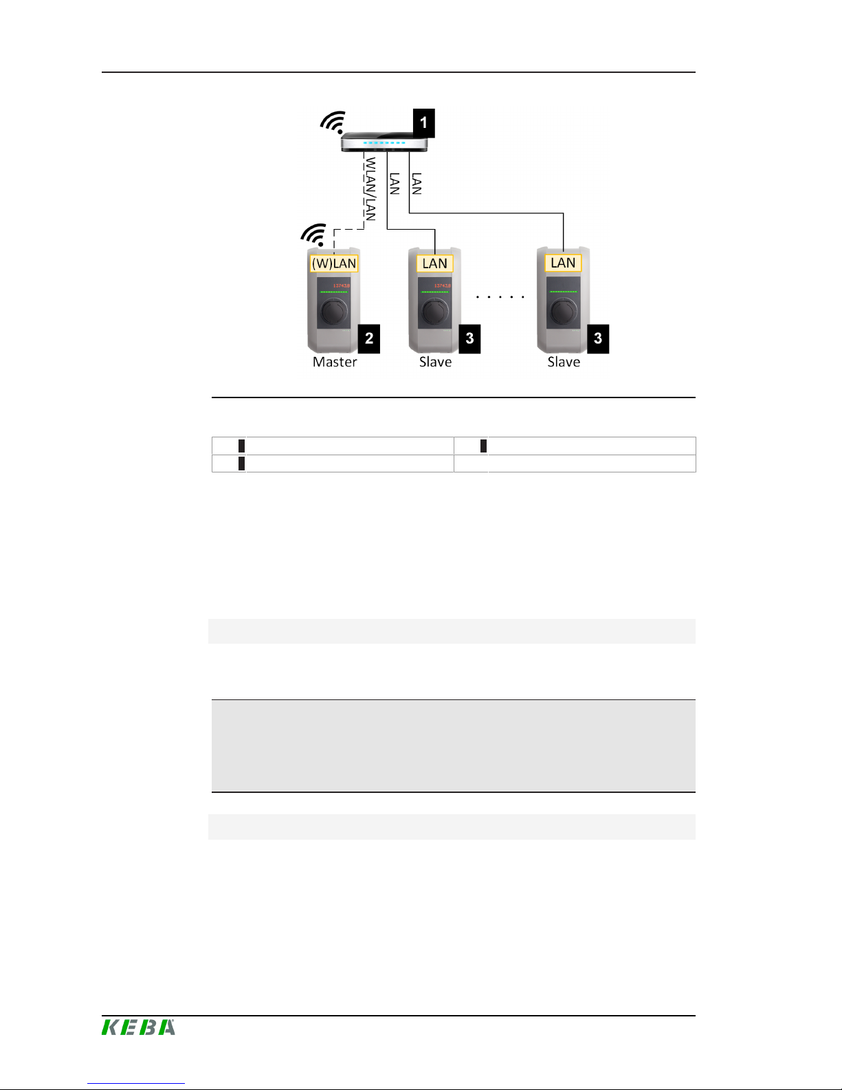
3.2.3 Connection via router or switch
If there are multiple slave charging stations, these must be connected to the
master charging station via a router or switch.
Page 18
P30 x-seriesSystem overview
Configuration manual V4.00
18
© KEBA
Illustration3-4: Connection via router or switch
1 ... Router/Switch 2 ... P30 x-series (master)
3 ... P20/P30 c-series (slave)
The interfaces used when connecting to the router or switch are dependent
on the type of charging station.
● Slave charging station: The connection of the slave charging station to
the router/switch is always made via LAN.
● Master charging station: The master charging station can be connected to the router/switch via LAN or WLAN.
Using a router
In a network connection using a router, the router automatically provides the
functionality of a DHCP server in most cases.
Information
If the IP addresses are assigned externally (for example, by routers with activated DHCP server), the IP addresses must not be in the following range:
192.168.25.xxx
Using a switch
For a network connection using a switch, the master charging station must
be configured as a DHCP server. The IP addresses are then assigned by
the master charging station.
Page 19

P30 x-series System overview
Configuration manual V4.00
19
© KEBA
3.2.4 Ports for communication in the charging network
For the correct communication in the charging network, the ports below must
be enabled network-internally.
Information
If necessary, contact your network administrator to enable the ports.
Port Protocol Definition Description
49153 TCP Within the network Socket of the charging station
15118 TCP Within the network
Link connection between the charging stations (SDP)
15118 UDP Within the network
Link connection between the charging stations (SDP)
68 TCP Within the network
Transfer of the software update
(Bootps)
68 UDP Within the network
Transfer of the software update
(Bootps)
67 TCP Within the network
Transfer of the software update
(Bootps)
67 UDP Within the network
Transfer of the software update
(Bootps)
Page 20

P30 x-seriesConfiguration
Configuration manual V4.00
20
© KEBA
4 Configuration
This chapter describes the necessary configuration for the correct operation
of the charging stations. The following steps are necessary for this:
● Set the DIP switch on the charging station
● Configuration (via the web interface or via USB stick)
Depending on the network configuration, activation of the DHCP server on
the master charging station may be necessary.
4.1 Connection panel
In the connection panel of the charging station are important interfaces and
controls for the configuration of the charging station. To access, the housing
cover and the connection panel cover must be removed.
Illustration4-5: Connection panel
DSW1 ... DIP switch configuration DSW2 ... DIP switch addressing
Service ... Service button LED ... Status LED
X1 ... Enable input X2 ... Switch contact output
X3 ... Ethernet2 connection (RJ45) X4 ... Ethernet1 connection (LSA+)
SIM ... Slot for SIM card (GSM module is
optional)
USB ... USB interface
Shd ... Ground for Ethernet1 connection
4.2 DIP switch settings
This DIP switch setting must be made for each master and slave charging
station to enable charging station communication.
Page 21

P30 x-series Configuration
Configuration manual V4.00
21
© KEBA
Information
Possible damage to the DIP switches!
The DIP switches are rocker switches and not slider switches. The DIP
switches must be pressed and must never be slid.
ON/OFF position of the rocker switches
The illustration shows the position of the rocker switches for the setting ON
and OFF
The DIP switches are located under the connection panel cover. The following figure shows only the affected DIP switches, others are not shown. The
following setting must be made on the DIP switch DSW2:
Activation of communication - DSW2-5
Function Figure
Activation of communication
Information
Changes to the DIP switch settings only become effective after a restart of
the charging station!
To restart, press the "Service button" until the first signal tone sounds (approx. 1 second) or switch off the charging station for a short time via the
line circuit breaker.
4.3 Configuration via web interface
The necessary settings (main menu "Configuration") for the communication
between the charging stations are configured in the web interface. The configuration for the entire charging network is done via the master charging
station.
Page 22
P30 x-seriesConfiguration
Configuration manual V4.00
22
© KEBA
A network connection is required to access the web interface of the master
charging station. The network connection can be made via LAN, WLAN,
WLAN access point or GSM (e.g. with PC or mobile device).
The web interface of the master charging station can be accessed by entering the IP address of the master charging station in a web browser.
The IP address of the master charging station is determined differently depending on the connection type.
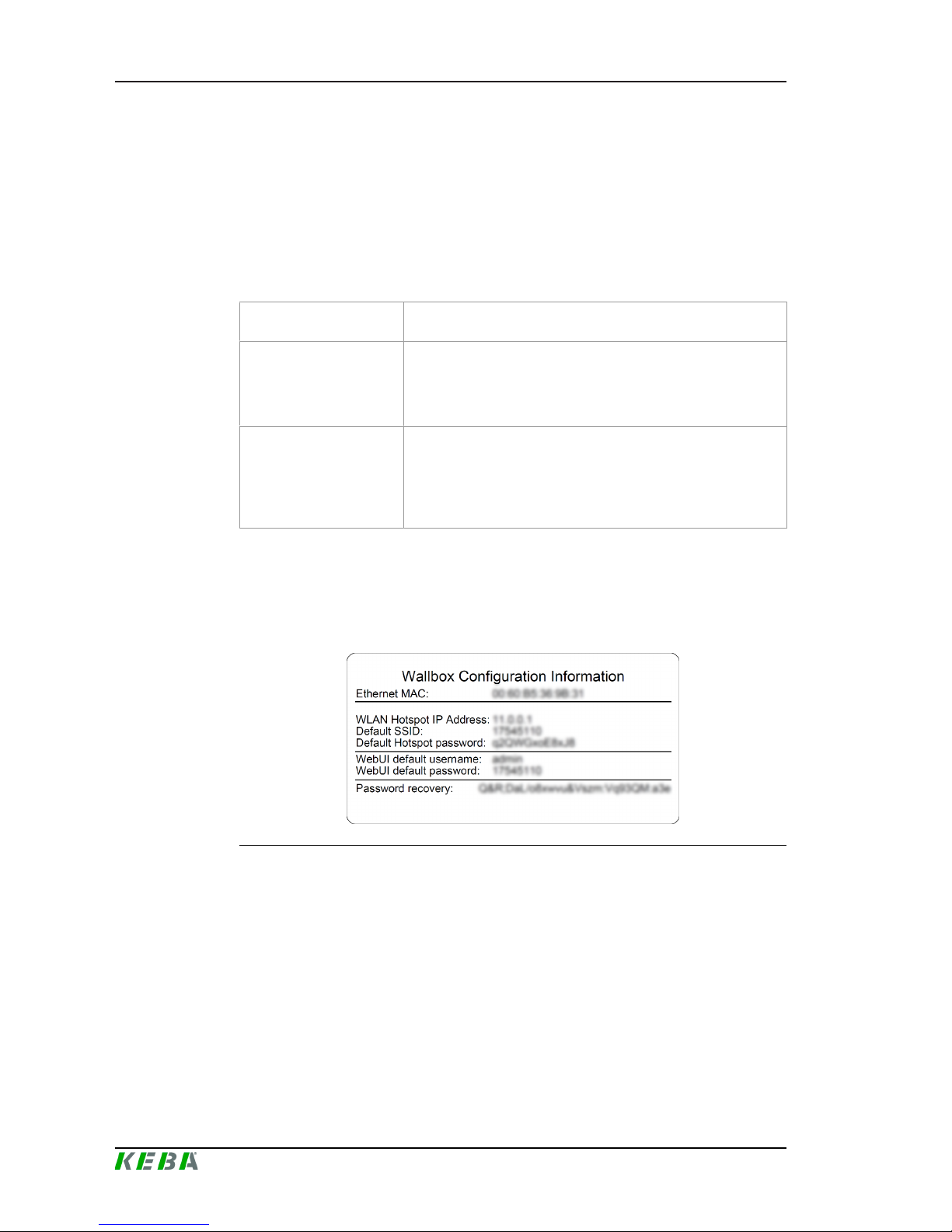
WLAN access point
The IP address of the WLAN access point is printed on the configuration label.
Router with integrated
DHCP server
The charging station automatically receives an IP address via
the DHCP server of the router. The IP address is displayed on
the charging station display when the charging station is
(re)started. The IP address can also be determined via the
router.
Master charging station
with local DHCP server
The local DHCP server has been activated for the master
charging station, which automatically gives the master charging
station the following IP address: 192.168.42.1
The DHCP server of the charging station is deactivated in the
delivery state and can be activated via the configuration.
A login is required to use the web interface.
The login data for the first login in the web interface is printed on the configuration label. The configuration label is in a pouch affixed to the manual set.
For security reasons, change the password after the initial login.
Illustration4-6: Configuration label
After successful login, the start page of the web interface opens.
Page 23

P30 x-series Configuration
Configuration manual V4.00
23
© KEBA
Illustration4-7: Web interface start page
1 ... Main menu 2 ... User menu
The following chapters provide an overview of the possibilities of the web interface. A detailed description of the individual configuration options can be
found directly next to the respective configuration entry.
4.3.1 Main menu
The main menu is divided into the following areas:
● Status
● System
● Configuration
Status
The area shows basic information about the configured charging stations
(such as: serial number, IP address, ...). Clicking on the respective IP address opens the KeContact "Information Center" in a new browser window. It
displays charge information such as total power, charge session power,
power, voltage, current, state, and basic log. The scope of the displayed information is variant-dependent.
System
The area offers the following options:
● Software update
● GSM signal test
● Logging
● Restart system
Software update
Page 24
P30 x-seriesConfiguration
Configuration manual V4.00
24
© KEBA
The currently installed software versions are displayed. A software update
can also be performed here.
GSM signal test
Here, the connection to the set GSM network can be testet.
Logging
Different log messages of the master charging station are displayed.
Restart system
The master charging station can be restarted using this button.
Configuration
The basic configuration of the charging stations is carried out in this area.
Information
The DIP switch settings are independent of the web interface configuration
and can not be overwritten by software.
The area offers the following options:
● Device
● Network connection
● WLAN hotspot
● OCPP
● Load management
Information
The settings made are only applied after the "Apply" button has been
pressed.
Device
The basic settings for the master/slave network (such as authorization, slave
charging stations, ...) are configured here.
The number of slaves must be entered for a charging network. For this purpose, all attached slave charging stations must be entered into the configuration with their respective serial numbers. Otherwise, the slave charging
station will not be recognized by the master charging station in the network.
The serial number is printed on the rating plate of the slave charging station.
The source for time synchronization of the charging station (e.g. time server
or OCPP backend) can also be set here.
Page 25

P30 x-series Configuration
Configuration manual V4.00
25
© KEBA
Information
If there is a time difference of more than 60 seconds, an automatic time
synchronization is performed. Thereafter, the charging station is restarted.
Network connection
The network communication can be selected and configured here.
WLAN hotspot
The WLAN hotspot can be enabled or disabled.
OCPP
All the necessary configurations for connecting to an OCPP backend can be
found in this part.
Load management
The desired current limits can be set here.
4.3.2 User menu
The user menu contains important information and settings for the user. It is
divided into the following areas:
● Help
● Licenses
● User settings
● Logout
User settings
This section allows you to make changes to the web interface user name
and associated password. The "recovery key" is also displayed here, which
can also be found on the configuration label. If you have forgotten the web
interface password, you can reset it with the displayed recovery key.
Information
The recovery key must be kept for the entire life of the product!
Page 26

P30 x-seriesConfiguration
Configuration manual V4.00
26
© KEBA
4.4 Enabling the DHCP server
To simplify the setup of a charging network, the master charging station can
be configured as a DHCP server. This function is required for the network
configuration when the master and one slave are connected directly or when
a network connection is implemented via switch.
The DHCP server of the master charging station is deactivated in the delivery state and can be activated via the configuration in the web interface.
4.5 Configuration in series via USB stick
If you are configuring several master charging stations with the same settings, a created configuration can be saved on a USB stick and thus transferred to other master charging stations.
This requires a (via the web interface) preconfigured master charging station, an empty FAT32 formatted USB stick and a PC.
The following steps are required:
● Read out configuration
● Adapting the configuration
● Import configuration
Read out configuration
In order to be able to transfer the configuration of a master charging station
to additional master charging stations, the USB stick must be connected to
the USB interface (in the connection panel) of the operationally ready and already configured charging station. The charging station automatically transfers the configuration to the USB stick and displays the process on the display. When finished, the charging station indicates that the USB stick can be
removed by displaying "remove usb" .
Information
Do not remove the USB stick during the writing process! Otherwise it can
not be used for another configuration.
Adapting the configuration
If necessary, the configuration saved on the USB stick can be adapted manually. The configuration was saved on the USB stick in the directory CFG as
*.conf file. This file can be opened and customized with a text editor on the
PC.
For more information, see the "USB Configuration Guide" (available online).
Page 27

P30 x-series Configuration
Configuration manual V4.00
27
© KEBA
Import configuration
To load the configuration into another master charging station, the USB stick
must be plugged in to the desired charging station. The configuration will be
imported automatically and adopted after a restart.
The configuration file (P30.conf) on the USB stick can be used to configure
multiple charging stations. If the saved configuration is only valid for exactly
one master charging station, the serial number of the charging station must
be added to the name of the saved configuration file.
P30_[serial number].conf
Page 28

P30 x-seriesFunctions
Configuration manual V4.00
28
© KEBA
5 Functions
The following chapters describe special functions of the charging station.
5.1 Load management in the local charging network
Load management in a local charging network allows multiple KeContact
charging stations to operate on a common supply. The maximum power allowed by the supply line is divided by the master charging station.
5.1.1 Equal allocation mode
If the parallel active charging stations in a local charging network request
more power than the power supply provides (set maximum current), the
available charging current is divided evenly across all charging sessions.
Charging current per charging station = set maximum current / number
of charging stations
If insufficient power is available for an additional charging process in the
charging network (set minimum current is underrun), the new charging
process will be queued. Every 15 minutes, an active charging session is
paused in sequence, queued to the back of the queue, and the next charge
session in the queue continues.
5.1.2 Current limiting
The current limiting for the charging station can be regulated in various
ways.
● Setting by means of DIP switches locally on each charging station
● Specification by master charging station for the entire charging network
● Specification via UDP connection for the entire charging network
If a current limit is specified via several different types, then the lowest preset
value is used for the currently valid current limit.
5.2 RFID authorization
Certain device variants are equipped with an RFID reader, which enables
the authorization of a charging process with RFID cards in accordance with
ISO 14443 and ISO 15693. The RFID authorization only allows a charging
session to be started if an identification takes place by means of an RFID
card.
The following chapters will first explain the displays and signals and then describe the procedure for authorization using RFID.
Page 29

P30 x-series Functions
Configuration manual V4.00
29
© KEBA
In the case of a local charging network without a higher-level OCPP backend, all RFID cards must be taught in at the master charging station and the
authorization function activated via its web interface. Up to 1024 RFID cards
can be stored. After teaching in, the permitted RFID cards are stored at the
master charging station and are enabled by the latter throughout the entire
charging network. It is not possible to teach in RFID cards at a slave charging station.
When connecting to an external OCPP backend, all RFID cards must be
taught in at the OCPP backend and the authorization function must be activated. Any number of RFID cards can be stored. It is not possible to teach in
the RFID card directly at a charging station.
Behavior in the event of connection failures
In order to be able to temporarily authorize charging sessions in case of connection failures, the following behavior has been implemented:
The first 1024 RFID cards are relayed from the OCPP backend to the master
charging station where they are stored locally. If the connection to the
higher-level OCPP backend terminates, the master charging station authorizes these stored RFID cards throughout the network until the connection is
reestablished.
In addition, the first taught-in 20 RFID cards are relayed from the master
charging station to each slave charging station. If the connection to the master charging station is terminated, these stored RFID cards are authorized by
the individual slave charging stations until the connection is restored.
5.2.1 Displays and signals
During RFID authorization, the charging station can display different light
patterns on the LED bar and emit acoustic signals.
LED bar
Signal Description Status
Flashing green
In standby mode of the
charging station (idle
mode), all 4 segments of
the LED bar flash green.
No authorization is required for a charging
session.
Flashing blue
In standby mode of the
charging station (idle
mode), all 4 segments of
the LED bar flash blue.
An authorization is required for a charging
session. Authorization necessary, either with
RFID card or by an external input.
Illuminated orange
All 4 segments of the LED
bar light up once in orange.
The RFID card is invalid.
Page 30

P30 x-seriesFunctions
Configuration manual V4.00
30
© KEBA
Acoustic signals
Signal Description
Single tone RFID card has been read
Rising tone sequence RFID card has been accepted
Falling tone sequence RFID card has been rejected (no authorization)
5.2.2 RFID authorization without OCPP backend connection
The authorization function must be activated in the configuration of the master charging station.
Teaching in a master RFID card
To teach in a master card, no charging session may be active and no vehicle
may be plugged into the charging station. To access the Service button, the
housing cover and the connection panel cover must be removed.
1) Press and hold the "Service button" in the connection panel until the
second signal tone is sounded (approx. 10s).
The charging station will then automatically perform a restart, deleting all
previously taught-in cards, if necessary.
2) The charging station will be available again after 30 seconds.
3) After the waiting time, a master card can be taught in for 30 seconds by
holding it in front of the RFID reader.
A successful programming process is confirmed by a rising tone sequence.
Teaching in a slave RFID card
To teach in a slave card, no charging session may be active and no vehicle
may be plugged into the charging station.
1) Hold the master card in front of the RFID reader and wait for the rising
tone sequence.
2) Then hold the slave card to be programmed in front of the RFID reader
within 10 seconds and wait for the signal tone.
3) Confirm the teach-in process by holding up the master card again within
5 seconds. The process is completed with a rising tone sequence.
5.2.3 RFID authorization with OCPP backend connection
If the charging station or a charging network is controlled by an OCPP backend, please note the following:
● Teach in cards:
All RFID cards must be "centrally taught in" at the OCPP backend.
● "Authorization" in configuration to "ON":
Each authorization request is relayed to the OCPP backend.
Page 31

P30 x-series Functions
Configuration manual V4.00
31
© KEBA
● "Authorization" in configuration to "OFF":
A charging process can only be started without holding up an RFID card
if the predefined token set in the configuration is recognized and accepted by the OCPP backend.
Information
For information on the functionality and the required settings of the OCPP
backend, refer to the specific manual of the system used.
5.2.4 Start charging procedure with RFID authorization
1) Plug the vehicle into the charging station.
2) Hold the RFID card, which was previously taught in, in front of the RFID
reader.
3) The rising tone sequence and the green flashing LED bar indicate that
the RFID card has been accepted. The charging session is started.
Information
Enable input [X1]
For special device variants, the enabling of a charging session can also be
controlled via the enable input [X1] (for connecting external components
such as a timer, photovoltaic system or home control). If this function has
been activated in the DIP switch settings, enabling a charging session will
additionally require a correct signal on the enabling input. Further information can be found in the "Installation Manual".
5.3 OCPP backend
The charging station offers the option of being connected to a central management system via the Open Charge Point Protocol (OCPP). OCPP, as an
open application protocol, makes it possible to connect any central management system to the charging station regardless of the manufacturer or supplier.
When connecting to an OCPP backend, note the following:
● It is recommended that the master charging station on the network be
assigned a static IP address based on the MAC address of the device.
● Since the OCPP backend is usually not in the same network, the charging station must be assigned a "public IP address" which is routed to the
internal IP address (NAT).
● The firewall must be configured so that a communication between the
charging station and the OCPP backend is possible.
Page 32
P30 x-seriesFunctions
Configuration manual V4.00
32
© KEBA
● For a connection via VPN, the IP address of the VPN must be specified
in the configuration for the downlink.
● In the case of a GSM connection, it may be necessary for the required
ports to be activated by the cellular service provider.
Ports for communication via OCPP
For communication with an OCPP backend, the following ports must be enabled in the network:
Port Protocol Definition Description
Custom
(1025 -
65535)
TCP
Can be reached externally
(incoming)
OCPP Charge Point Service: This
service is related to the OCPP
backend.
● The port can be freely selected
or it is specified by the OCPP
backend. However, the port
may only be located in the
range from 1025 to 65535.
● The selected port must be
configured on the charging
station.
Custom TCP
Access to external (outgoing)
Port at which the OCPP backend
can be reached.
123 UDP Incoming and outgoing
Port for the timer server of the
charging station.
5.4 UDP interface
The charging station offers the possibility of passing information and receiving commands via the UDP protocol. This can be used, for example, for integration into a SmartHome. Information on this can be found in the UDP Programming Guide on the KEBA website.
Page 33

P30 x-series Diagnosis and troubleshooting
Configuration manual V4.00
33
© KEBA
6 Diagnosis and troubleshooting
The FAQs on the KEBA website help to rectify possible errors that might occur:
http://www.keba.com/de/emobility/service-support/faqs/faqs-inbetriebnahmetechniker
Page 34

P30 x-seriesMaintenance
Configuration manual V4.00
34
© KEBA
7 Maintenance
7.1 Software update
It is recommended to always keep the charging station up-to-date, as it contains functional enhancements and bug fixes. A software update is available
on the KEBA website (http://www.keba.com/de/emobility/service-support/
downloads/downloads).
The information and instructions for the current software package from the
associated release notes must also be observed.
Information
A software update may only be performed if no vehicle is plugged in at the
charging station.
Caution
The power supply may not be interrupted during the software update!
This can lead to the destruction of the software on the charging station and
thus make further operation impossible.
Information
The software update can take up to an hour. The update process is indicated by a slow orange flashing of the LED bar.
After the software update, the charging station restarts automatically. The
LED bar will flash blue or green, depending on the authorization setting.
Software update at charging network
A software update for a charging network must be performed at the master
charging station. The master charging station relays the new firmware to the
connected slave charging stations via the software update. When connected
to an OCPP backend, the software update for the entire charging network
can also be performed via the OCPP backend.
Page 35
P30 x-series Maintenance
Configuration manual V4.00
35
© KEBA
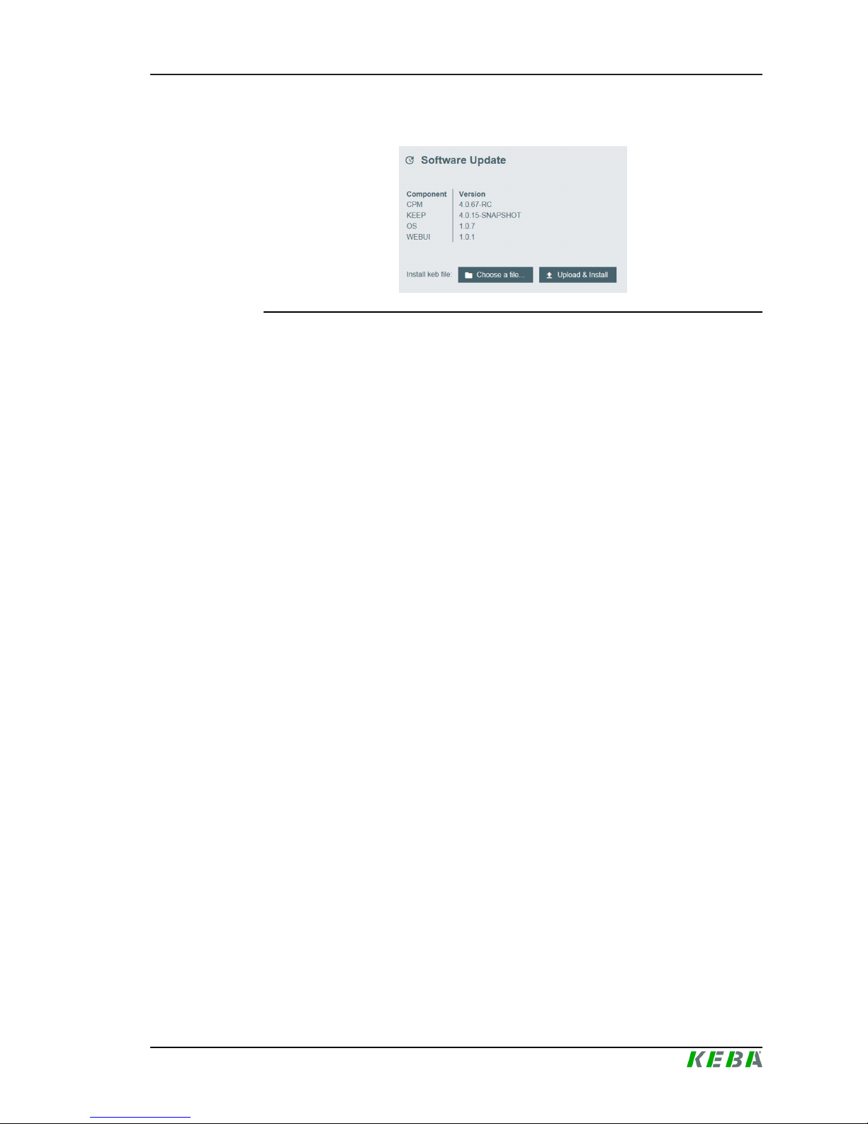
7.1.1 Software update via web interface
Illustration7-8: Web interface software update
To perform a software update via the web interface, the following steps are
necessary:
1) Download the current software for the charging station (* .keb file).
2) Log into the web interface of the charging station.
3) In the menu bar under "System" select the item "Software Update".
4) Upload the current software using the "Choose a file ..." button.
5) Start the update process with the "Upload & Install" button.
7.1.2 Software update via USB stick (x-series only)
To perform a software update via a USB stick, the following steps are necessary:
1) Download the current software for the charging station (* .keb file).
2) Plug the USB stick into a PC.
3) Format the USB stick with FAT32.
4) Create a new directory on the USB stick with the name "UPD".
5) Copy the downloaded *.keb file into the "UPD" directory.
6) Connect the USB stick to the USB interface of the charging station. The
update starts automatically.
Page 36

P30 x-seriesIndex
Configuration manual V4.00
36
© KEBA
Index
C
Charging network ....................................16
Direct connection ................................ 17
Load management.............................. 28
Ports for communication ..................... 19
Router ................................................. 17
Software update.................................. 34
Switch ................................................. 17
Configuration
DHCP server....................................... 26
DIP switch........................................... 20
USB stick ............................................ 26
Web interface...................................... 21
Configuration in series............................. 26
Current limiting ........................................28
D
DHCP server ...........................................26
DIP switch ............................................... 20
E
Equal allocation mode .............................28
G
GSM ........................................................15
L
LAN ......................................................... 13
Load management .................................. 28
M
Master charging station ...........................16
N
Network interfaces
GSM.................................................... 15
LAN..................................................... 13
WLAN .................................................13
WLAN Access Point (Hotspot)............ 14
O
OCPP backend........................................ 31
Ports for communication ..................... 32
R
RFID authorization .................................. 28
Acoustic signals .................................. 30
Connection failures ............................. 29
LED bar............................................... 29
Master RFID card ............................... 30
OCPP backend ................................... 30
Slave RFID card ................................. 30
Start charging procedure .................... 31
Router...................................................... 17
S
Slave charging station .............................16
Software update ......................................34
Switch...................................................... 17
U
UDP interface ..........................................32
USB stick................................................. 26
W
Web interface ..........................................21
WLAN ......................................................13
WLAN Access Point (Hotspot) ................ 14
Page 37

Page 38

KEBA AG Headquarters
Gewerbepark Urfahr
4041 Linz / Austria
www.keba.com
 Loading...