

Page 1
KeContact P20/P30
Standsä ule –
Installationsanleitung
Floor-mounted column –
Installation guide
Colonne –
Notice d'installation
Instruc ciones de i nstalación
del poste
Colonnina portante –
Istruzioni per l'installazione
Standzuil – Installatiehandleiding
Deutsch
(4)
English
(10)
Français
(16)
Español
(22)
Italiano
(28)
Nederlands
(34)
Coluna vertic al –
Instruções de instalação
安装架 - 安装说明书
スタンドサポート – 設置説明書
© KEBA 2012-2016
Specifications are subject to change due to ongoing technical development. Errors and
omissions excepted. All rights reserved.
All intellectual property, including trademarks and copyrights, is the property of the respective owner. Any unauthorized use of such intellectual property is expressly forbidden.
KEBA AG, Postfach 111, Gewerbepark Urfahr, A-4041 Linz
KeContact P20/P30 - Floor- mounted column, v2.40, #90333
Português
(40)
中文
(46)
日本語
(52)
Page 2
V1
2 KeCont act P20/P3 0 - Floor-mounted column, v2.40, #90333
© KEBA 2012-2016
Page 3
V2
KeCont act P20/P3 0 - Floor-mounted column, v2.40, #90333 3
© KEBA 2012-2016
Page 4

DE
Standsäule
–
Installationsanleitung
!
WARNUNG!
Sicherheitshinweise
Nichtbeachtung der Sicherheitshinweise kann zu Lebensgefahr, Verletzungen und
Schäden am Gerät führen! KEBA AG lehnt jede Haftung für daraus resultierende
Ansprüche ab!
l Elektrische Gefahr!
Die Montage, erste Inbetriebnahme und Wartung der Stromladestation darf nur
von einer einschlägig ausgebildeten, qualifizierten und befugten Elektrofachkraft durchgeführt werden, der dabei für die Beachtung der bestehenden Normen und Installationsvorschriften verantwortlich ist.
l Halten Sie die angeführten Vorgaben für die Standortauswahl und die bauli-
chen Voraussetzungen ein!
Abweichungen zu den Standortvorgaben können zu Tod, schweren Körperverletzungen oder Sachschäden führen, wenn die entsprechenden Vorsichtsmaßnahmen nicht getroffen werden!
Gebrauch dieses Handbuches
Dieses Installationshandbuch wendet sich ausschließlich an qualifiziertes Personal1.
Diese Anleitung ist eine Ergänzun g zum „KeContact P20/P30 Installationshandbuch“. Alle im
Handbuch enthaltenen Hinweise und Anweisungen zu Standortauswahl, Montage und zum
Anschlus s der Stromladestatio n müssen b eachtet werden!
Bestimmungsgemäßer Gebrauch
Alternativ zur Montage der KeContact P20/P30 Stromladestation auf einer Wand, steht eine
Standsäule zur freist ehenden Montage im Innen- oder Außenb ereich zur Verfügung.
Je nach Ausführung und Anzahl der Stromladestationen (Standsäule V1 oder V2) muss eine
unterschiedliche Anzahl von Anschlusskabel und Leerrohre im Betonfundament berücksichtigt werden.
Wird die Stromladestation mit einer steckbaren Versorgungsleitung installiert (z .B. für Demonstrationszwecke), ist für die Versorgun gsleitung eine ausreichende Zugentl astung sowie
ein Kantenschutz vorzusehen.
Für die Montage der Standsäule sind die jeweiligen nationalen Vorschriften zu beachten.
Gewicht: 12,5 kg (ohne Stromladestation)
1
Personen die aufgrund fachlicher Ausbildung, Kenntnis und Erfahrung sowie Kenntnis der einschlägigen Nor-
men, die übertragenen Arbeiten beurteilen und mögliche Gefahren erkennen können.
4 KeCont act P20/P3 0 - Floor-mounted column, v2.40, #90333
© KEBA 2012-2016
Page 5
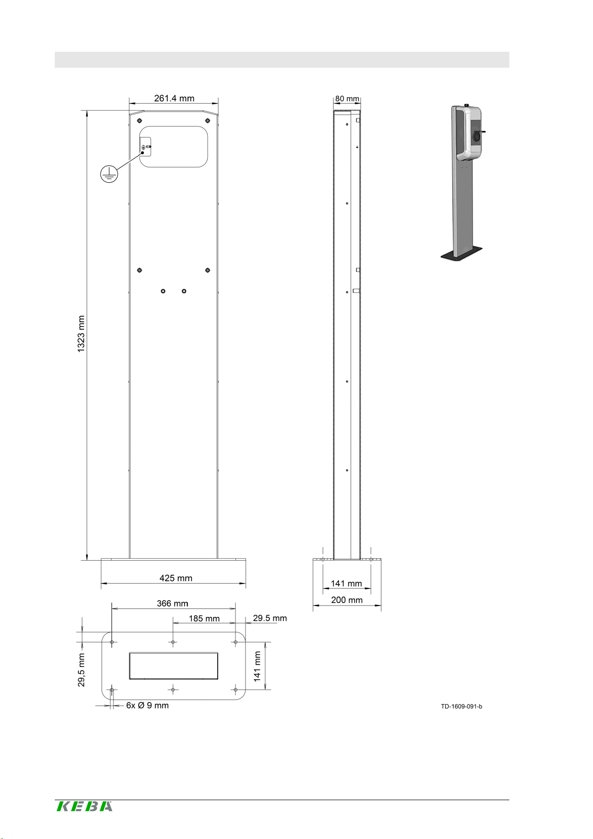
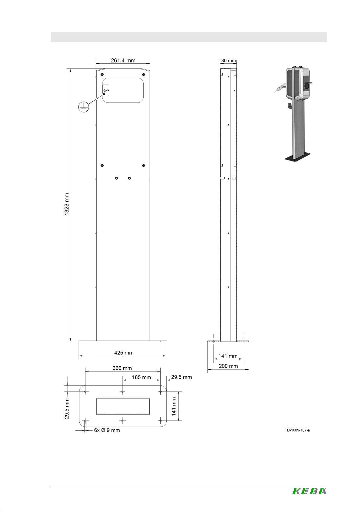
Übersicht
Standsäule
V1
Standsäule
V2
WARNUNG!
Standsäule V1
DE
Die Stan dsäule V1 ist für die Montage von einer
KeCont act P20/P 30 Strom ladestation au f der
Standsäule geeignet.
Die Standsäule V2 ist für die Montage von zwei
KeCont act P20/P 30 Strom ladestationen auf der
Standsäule geeignet.
Standsäule V2
!
l Elektrische Gefahr!
Die Standsäule V2 muss immer mit
zwei Stromladestationen bestückt
werden! Kabelöffnungen in der
Standsäule dürfen nicht offen bleiben.
KeCont act P20/P3 0 - Floor-mounted column, v2.40, #90333 5
© KEBA 2012-2016
Page 6
DE
Anforderungen an den Standort
Allgemeines:
· Alle Standortanforderungen für die Stromladestation aus dem „KeContact P20/P30
Installationshandbuch“ müssen beachtet werden!
· Bei der Montage der Standsäule auf Parkplätzen oder in Tiefgaragen ist bauseits ein
geeigneter Anfahrschutz vorzusehen.
Betonfundament:
· Die Berechnung, Auslegung und Herstellung des Betonfundaments liegt im Verantwortungsbereich des Standortherstellers.
· Für die Aufstellung ist waagrechter, ebener und tragfähiger Untergrund erforderlich.
Um eine sichere und dauerhafte Verankerung zu gewährleist en, empfehlen wir die Aus-
führung eines Betonfundaments:
65cm (L) x 50cm (B), Tiefe = mind. Frostgrenze jedoch > 40cm, frostsicher gegründet.
Beton: C3 0/37 LP für XC4, XD1, XF 4 bzw. C25/30 LP für XC4, XD1, XF2
Betonstahl: BSt 500 S; BSt 500 M
· Der Untergrund muss das Ablaufen von eventuell in den Sockel gelangendem Wasser
ermöglichen.
· Alle Kabel müssen genau in der Mitte des Betonfundamentes aus dem Boden geführt
werden und für die weitere Montage eine Überlänge von ca. 1,5 m aufweisen.
· Bei der Herstellung des Betonfundaments sind die Kabel mit geeigneten Mitteln gegen
Beschädigungen zu schützen (z.B. mit einem Schutzschlauch). Der Schutzschlauch
muss eine Überlänge von ca. 25 cm über dem Betonfundament aufweisen.
· Eine Aufstellung der Standsäule auf Asphalt ist nicht zulässig!
Verankerung am Boden
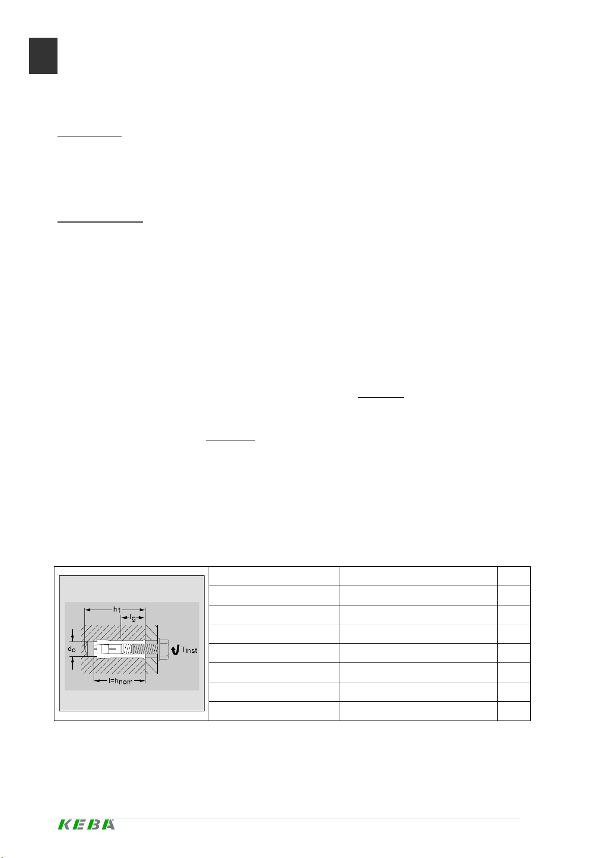
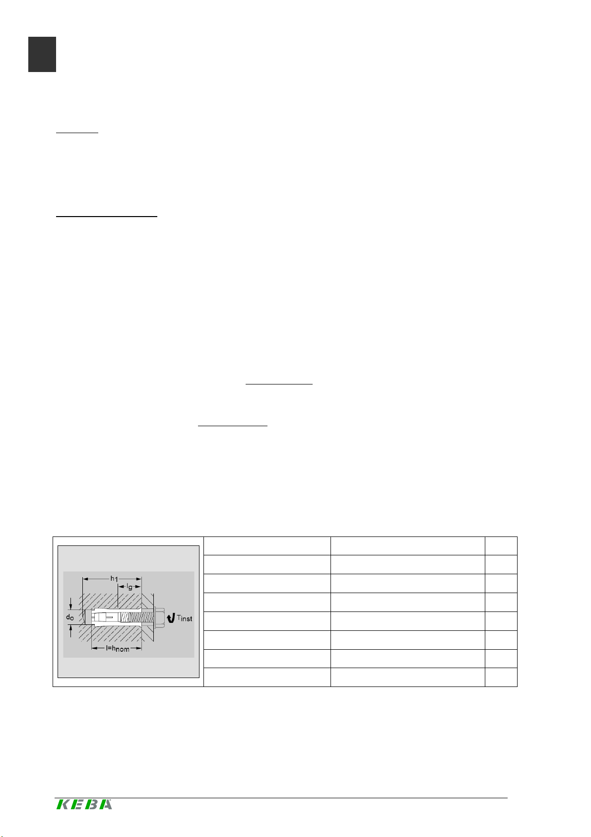
Zum Verankern müssen die beigelegten Dübel verwendet werden (6 Stück Kompaktdübel
Hilti HKD-ER M8x30).
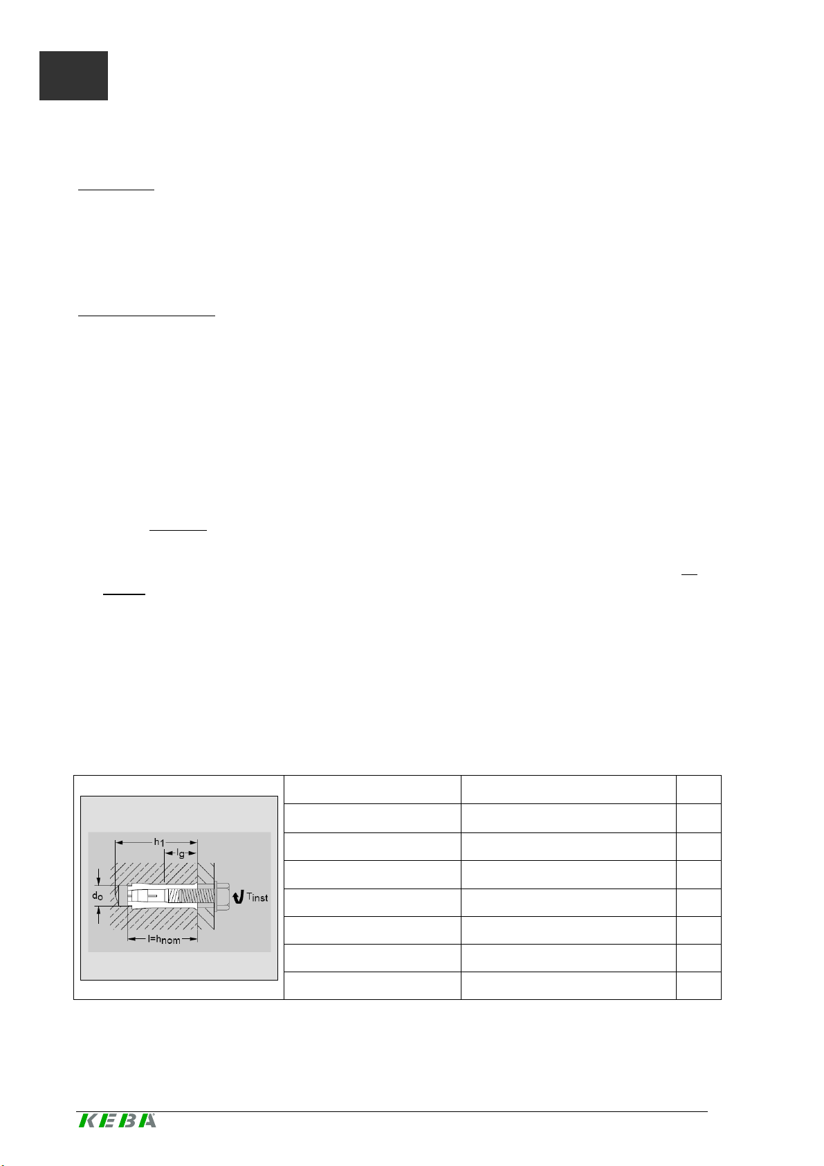
Technische Daten
Ankergrund Normbeton ab Festig ke itsklasse
C20/25-C 5 0/60
Empfohl en e L ast Zug N (ungerissener Beton) 4
Pro Dübel Querzug V (ungerissener Beton) 3,9 kN
Erforderlicher Randabstand 10,5
Drehmoment Tinst ≥8 Nm
Boh rlochdurchmesser do 10 mm
Bohrlochtiefe h1 33 mm
Spezifikation Kompaktdübel Hilti HKD-ER M8x30. Quelle: Fa. Hilti
M8
cm
6 KeCont act P20/P3 0 - Floor-mounted column, v2.40, #90333
© KEBA 2012-2016
Page 7
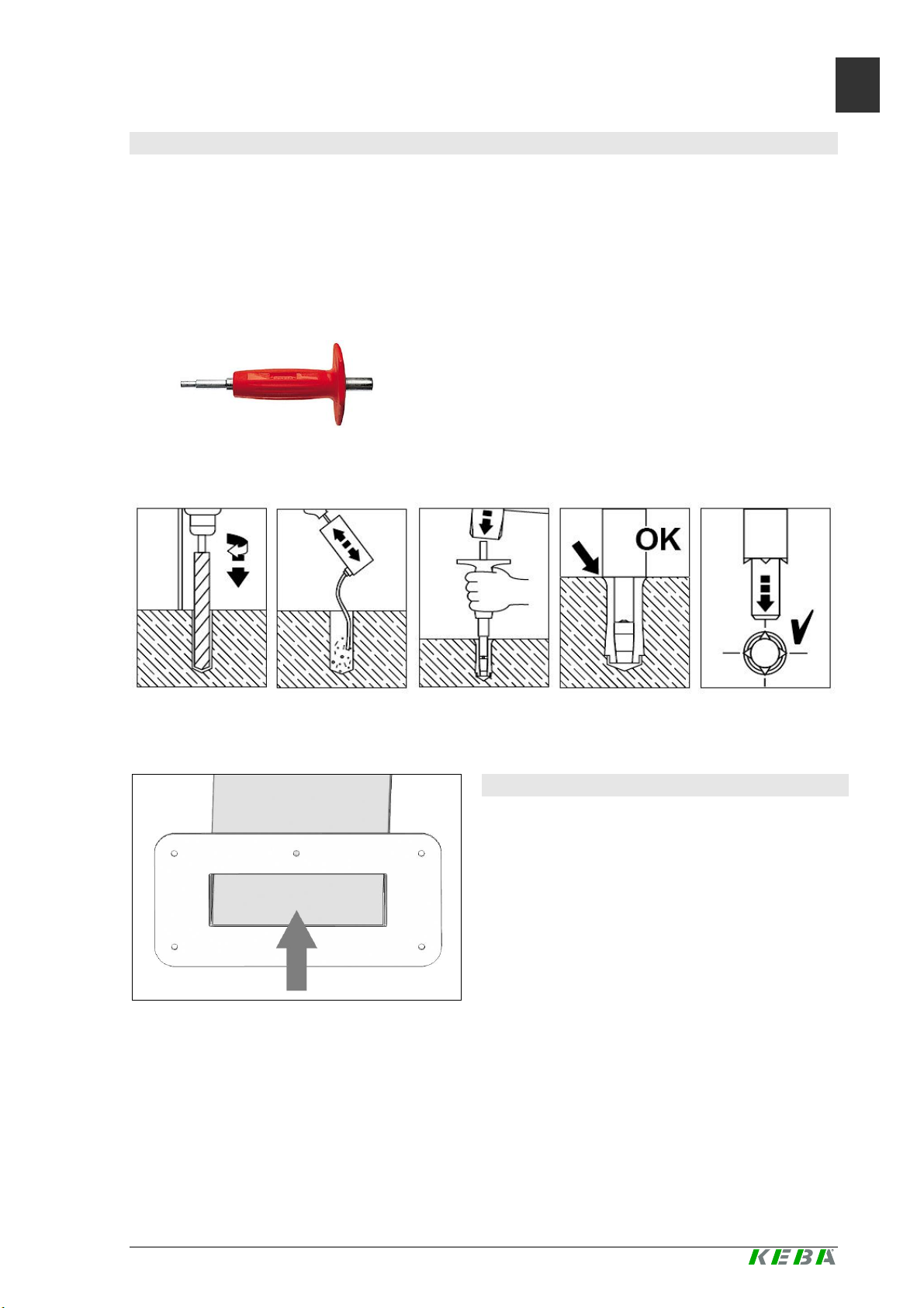
Bohrungen durchführen
Kabel einfädeln
► Zeichnen Sie die 6 Bohrungen mit Hilfe der Bodenplatte der Standsäule auf dem
Betonfu ndament an.
Stellen Sie sicher, dass sich die Anschlusskabel genau unter der Öffnung der
Bodenplatte der Standsäule befinden.
► Bohren Sie die 6 Befestigungslöcher:
Durchmesser: 10 mm
Bohrlochtiefe: 33 mm
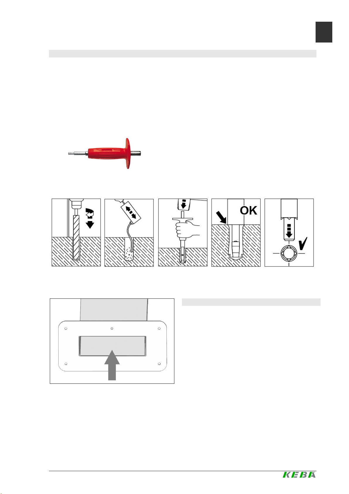
► Schlagen Sie die beigepackten Dübel mit dem Hilti HSD-G Hand-Setzwerkzeug (nicht
im Lieferumfang) so weit ein, dass sie mit dem Boden eben abschließen.
Hilti HSD-G Hand-Setzwerkzeug. Quelle: Fa. Hilti
Beachten Sie auch die folgende Anleitung:
DE
Anleitung zum Setzen der Dübel. Quelle: Fa. Hilti
Stands äul e von unten
► Fädeln Si e die Anschlussk abel von unten
durch die Standsäule nach oben zur
Kabelöffnung.
KeCont act P20/P3 0 - Floor-mounted column, v2.40, #90333 7
© KEBA 2012-2016
Page 8

DE
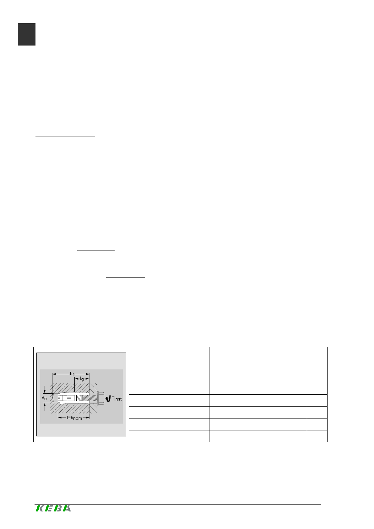
Verankerung
Erdung
Kantenschutz entfernen
Verankerung
► Positionieren Sie die Standsäule ü ber
dem Kabela uslass.
► Verankern Sie die Standsäule mit den
6 Sechskantschrauben am Fundament.
► Schließen Sie (falls erforderlich) die
Erdung am Erdungspunkt der Standsäule
an.
Erdungspunkt
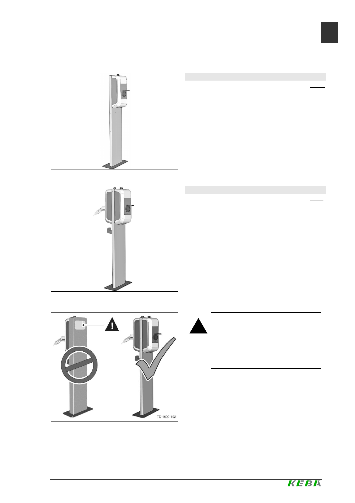
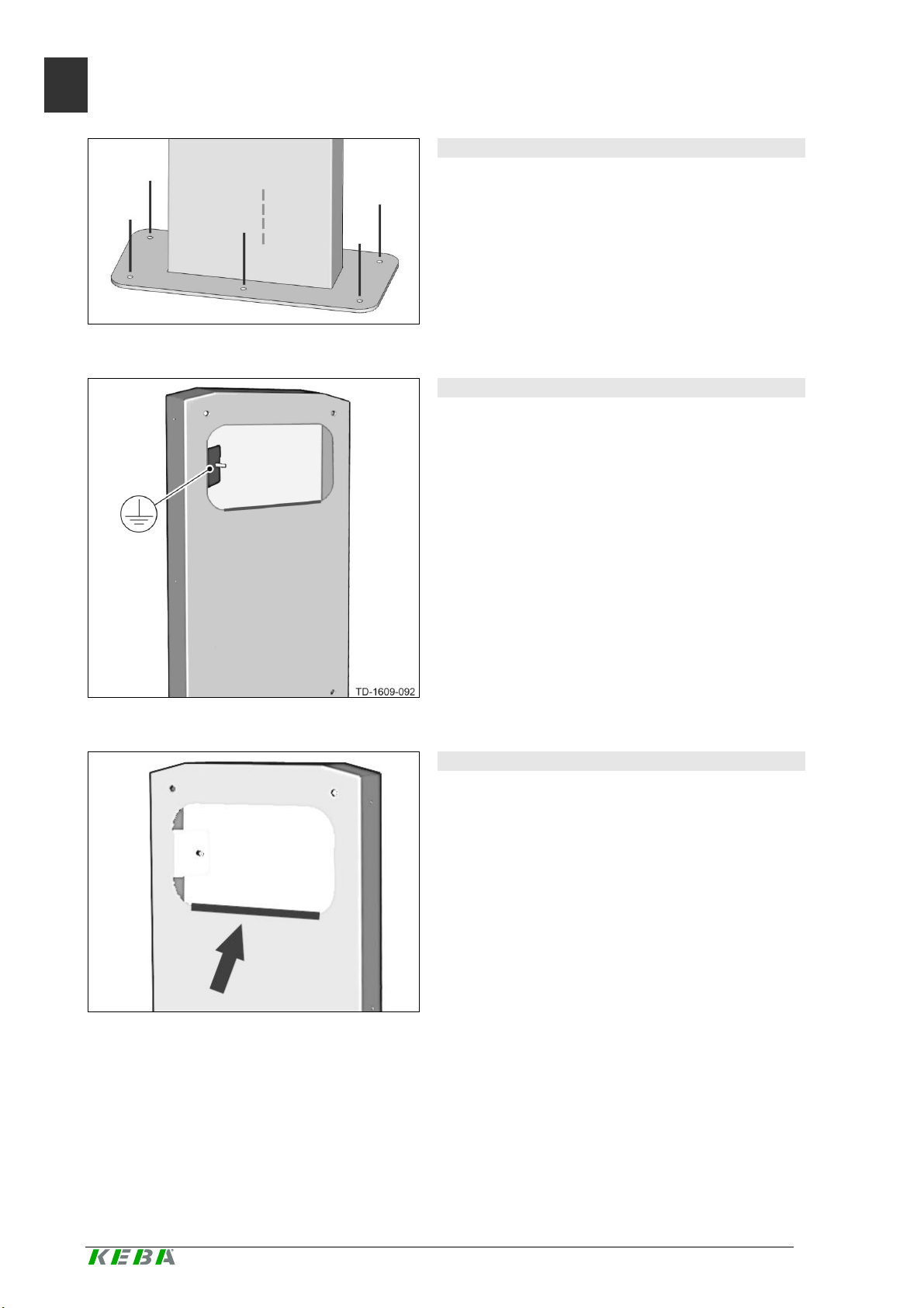
Kantens c hut z en tfernen
► Entfern en Sie den Kantenschutz an der
Kabelöffnung der Standsä ule erst
unmitt elbar vor der Montage der
Stromladestation (siehe Abbildung).
8 KeCont act P20/P3 0 - Floor-mounted column, v2.40, #90333
© KEBA 2012-2016
Page 9

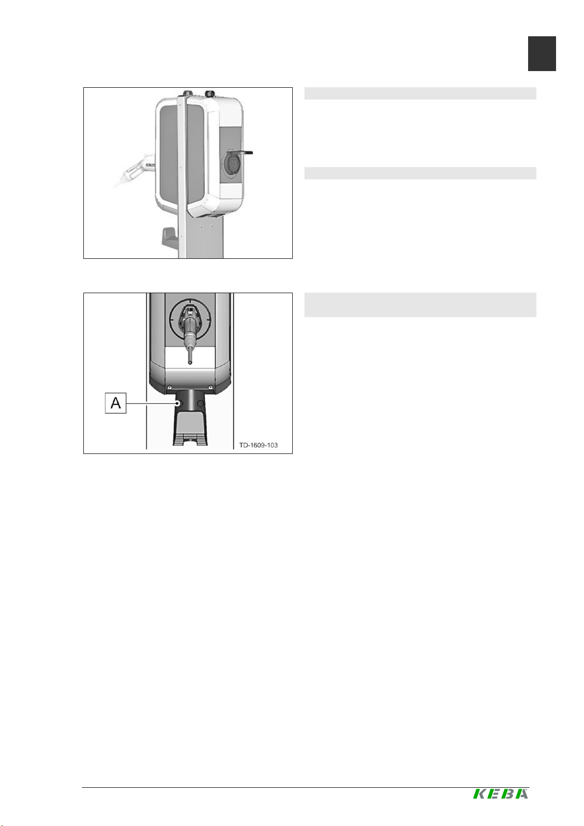
Beispiel Standsäule V2
Stromladestationen montieren
Halterung für Ladekabel montieren (Option)
DE
► Montieren Sie die Stromladestationen mit
den beiliegenden Schrauben auf der
Standsäule.
Anschluss und Inbetriebnahme
► Führen Sie den elektrischen Anschluss
und die Inbetriebnahme ents prechend der
Anleitung im „KeContact P20/P30
Installationshandbuch“ durch.
► Montieren Sie die Halterung für das
Ladekab el unterhalb der Str omladestation
mit zwei Schrauben [A] an der
Standsäule.
Halterung für Ladekabel
KeCont act P20/P3 0 - Floor-mounted column, v2.40, #90333 9
© KEBA 2012-2016
Page 10
EN
Floor
-
mounted column
-
Installation guide
!
WARNING!
Safety instructions
Not observing the safety instructions can result in risk of death, injuries and damage to the device! KEBA AG assumes no liability for claims resulting from this!
l Electrical hazard!
The installation, commissioning and maintenance of the charging station may
only be performed by correctly trained, qualified and authorized electricians
who are fully responsible for the compliance with existing standards and installation regulations.
l Observe the instructions given for selecting the location and the construction-
al requirements!
If the specifications for the location are not observed, this can result in death,
serious physical injury or equipment damage if the corresponding precautionary measures are not met!
Use of this manual
This installation manual is intended for qualified personnel only2.
This guide is a supplement to the "KeContact P20/P30 Installation Manual." The information
and instructions in the manual about selecting the location, installation and connection of the
charging station must be adhered to.
Intended use
A floor-mounted column for free-standing installation in inside or outside areas is available as
an alternative to mounting the KeContact P20/P30 charging station on a wall.
Depending on the desi gn and number of charging stations (V1 or V2 floor-mounted columns)
the relevant number of empty pipes and connection cables should be taken into consideration in the concrete foundation.
If the charging station is installed with a plug-in power supply line (e.g., for demonstration
purposes), you should ensur e that there is sufficient tension relief and edge protection for the
power supply lin e.
The respective national regulations must be observed with regard to the installation of the
floor-mounted columns.
Weight: 12.5 kg (without charging station)
2
Persons who, due to their special training, expertise and experience as well as knowledge of current standards,
are able to assess the work performed and the possible hazards.
10 KeCont act P20/P3 0 - Floor-mounted column, v2.40, #90333
© KEBA 2012-2016
Page 11

Overview
V1 floor
-
mounted column
V2 floor
-
mounted column
WARNING!
V1 floor-mounted column
EN
The V1 floor-mounted c olumn is designe d for
the inst allation of one KeContact P20/P30
charging station on the column.
The V2 floor-mounted c olumn is designe d for
the inst allation of two KeContact P20/P3 0
charging stations on the column.
V2 floor-mounted column
!
l Electrical hazard!
The V2 floor-mounted column must
always be fitted with two charging
stations! There can be no open cable openings in the column.
KeCont act P20/P3 0 - Floor-mounted column, v2.40, #90333 11
© KEBA 2012-2016
Page 12
EN
Location requirements
General:
· All of the location requirements for the charging station in the "KeContact P20/P30
Installation manual" must be adhered to!
· When mounting the floor-mounted columns in parking spaces or parking garages, appropriate anti-collision protection must be provided by the customer.
Concre te fo undation:
· The calculation, design and manufacture of the concrete founcation lies in the scope of
responsibility of the producer of the sit e.
· A horizontal, level and sound foundation is required for installation.
To ensure safe and permanent anchoring, we recommend creating a concrete founda-
tion:
65cm (L) x 50cm (W), depth = min. frost limit but > 40cm, frost-free.
Concrete: C30/37 LP for XC4, XD1, XF4 or C25/30 LP for XC4, XD1, XF2
reinforced concrete: BSt 500 S; BSt 500 M
· The base must permit the running off of any water that has entered the base.
· All cables must be laid precisely in the centre of the concrete foundation from the base
and must have an excess length of approx. 1.5 m for the remaining installation activities.
· During the production of the concrete foundation, the cables must be protected against
damage using appropriate measures (e.g., a protective tube). The protective tube must
have an excess length of approx . 25 cm above the concrete foundation.
· Mounting the column on asphalt is not allowed!
Anchoring to the base
The enclosed dowels must be used for a nchoring (6 x Hilti HKD-ER compact dowels M8x30).
Technical data
Anchorage grou nd Standard concrete with a strength
class of C20/25-C50/60 or greater
Recomm en d ed l oad Tension N (uncracked concrete) 4
Per dowel Transversal sh ear V (uncracked con-
crete)
Required clearance 10,5
Torque Tinst ≥8 Nm
Drill-hole diameter do 10 mm
Drill-hole depth h1 33 m m
Specifications for compact dowels Hilti HKD-ER M8x30. Source: Hilti
M8
3,9 kN
cm
12 KeCont act P20/P3 0 - Floor-mounted column, v2.40, #90333
© KEBA 2012-2016
Page 13

Making drillholes
Thread in cable
► Mark the 6 holes on the concrete foundation using the baseplate of the floor-mounted
column .
Make sure that the connection cable is located precisely underneath the opening in the
baseplate.
► Drill the 6 mounting holes:
Diameter: 10 mm
Drill-hole depth: 33 mm
► Hammer the enclosed dowels using the Hilti HSD-G manual setting tool (not included
in the scope of delivery) so that they are flush with th e floor.
Hilti HSD-G manual setting tool. Source: Hilti
Please also obser ve the following instructions:
EN
Instructions on inserting the dowels. Source: Hilti
Floor-mounted column from below
► Thread the connection cables from the
bottom through the column upwards
throug h the cable opening.
KeCont act P20/P3 0 - Floor-mounted column, v2.40, #90333 13
© KEBA 2012-2016
Page 14

EN
Anchoring
Grounding
Remove edge protection
Anchoring
► Position the column directly over the
cable outlet.
► Anchor t he column to the foundation
using the 6 hexagon bolts.
► If necessary, connect the earthing to the
column's grounding point.
Grounding point
Remove edge protection
► Remove the edge protection on the cable
opening of the column immediately before
installing the charging station (see figure).
14 KeCont act P20/P3 0 - Floor-mounted column, v2.40, #90333
© KEBA 2012-2016
Page 15
V2 floor-mounted column example
Mounting the charging stations
Mount the holder for the charging cable
EN
► Mount the charging stations on the
column using the enclosed screws.
Connecting and commissioning
► Perform the electrical connection and
commissioning in accordance with the
instructions in the "KeContact P20/P30
Installation manual."
(option)
► Mount the holder for the ch arging cable
on the floor -mounted colum n below the
charging station using two screws [A].
Holder for charging cable
KeCont act P20/P3 0 - Floor-mounted column, v2.40, #90333 15
© KEBA 2012-2016
Page 16

FR
Colonne
–
Notice d'installation
!
AVERTISSEMENT
!
Consignes de sécurité
Le non-respect des consignes de sécurité peut entraîner la mort, des blessures ou
l’endommagement de l’appareil ! KEBA AG décline toute responsabilité pour les
demandes qui en résulteraient !
l Danger électrique !
l Tenir compte des informations suivantes dans le choix du site et respecter les
Le montage, la première mise en service et la maintenance de la station de recharge doivent être confiés uniquement à un électricien compétent, qualifié et
autorisé qui porte l’entière responsabilité du respect des normes et des prescriptions d’installation existantes.
conditions structurelles !
Toute différence peut entraîner la mort, des blessures graves ou des dommages matériels si les mesures de sécurité correspondantes ne sont pas
prises !
Utilisation de ce manuel
Ce manu el d’instal lation s’adresse exclusivem ent au personnel qualifié3.
Cette notice complète le "Manuel d'installation KeContact P20/P30". Respecter les con-
signes et les instructions du manuel en ce qui concerne le choix du site, le montage et le
raccordement de la station de recharge !
Utilisation conforme
L'alternative au montage mural de la station de recharge KeContact P20/P30 est le montage
isolé sur colonne à l'intérieur ou à l'extérieur.
Selon le modèle et le nombre de stations de recharge (colonne V1 ou V2), le nombre de
câbles de raccor dement et de gaines dans la fo ndation en béton varie.
Si la station de recharge est installée avec un câble d'alimentation enfichable (par ex. à des
fins de dém onstration), prévoir une décharge de traction suffis ante et une protectio n de bord
pour le câble d'alimentation.
Respecter la réglementation nationale en vigueur pour le montage de la colonne.
Poids : 12,5 kg (sans station de recharge)
3
Personnes qui, en raison de leur formation technique, de leurs connaissances, de leur expérience et de leur
connaissance des normes en vigueur, sont capables d'évaluer les travaux qui leur sont confiés et d'identifier les
dangers potentiels.
16 KeCont act P20/P3 0 - Floor-mounted column, v2.40, #90333
© KEBA 2012-2016
Page 17

Aperçu
Colonne V1
Colonne V2
AVERTISSEMENT
!
Colon ne V1
FR
La colo nne V1 convient au montage d'une station de recharge KeContact P20/P30.
La colonne V2 convient au montage de deux
stations de recharge KeCo ntact P20/P30.
Colon ne V2
!
l Danger électrique !
La colonne V2 doit toujours être
équipée de deux stations de recharge ! Les ouvertures de câble de
la colonne ne doivent pas rester
ouvertes.
KeCont act P20/P3 0 - Floor-mounted column, v2.40, #90333 17
© KEBA 2012-2016
Page 18
FR
Exigences sur site
Généralités
· Respecter toutes les exigences relatives au site pour la station de recharge qui
figurent dans le "Manuel d'installation KeContact P20/P30" !
· Si la colonne est installée dans un parking ou dans un garage souterrain, prévoir une
protection contre les collisions adaptée.
Fondation en béton
· Le constructeur du site est responsable de l'élaboration, de la conception et de la cons-
truction de la fondation en bét on.
· L'installation exige un support horizontal, plan et résistant.
Pour garantir un ancrage sûr et durable, construire une fondation en béton ingélive dont
les caractéristiques sont les suivantes :
65 cm (l ongueur) x 50 cm (largeur), profondeur = au moins limite du gel mais > 40 cm.
Béton : C30/37 LP pour XC4, XD1, XF4 ou C25/30 LP pour XC4, XD1, XF2
Béton armé : BSt 500 S ; BSt 500 M
· La fondation doit permettre l'évacuation de l'eau éventuellement présente dans la se-
melle.
· Tous les câbles doivent ressortir du sol exactement au milieu de la fondation en béton et
dépasser d'env. 1,5 m pour poursuivre le montage.
· Lors de la construction de la fondation en béton, protéger les câbles contre les dom-
mages à l'aide d'accessoir es adaptés (par ex. une gaine). La gaine doit dépasser de la
fondation en béton d'env. 25 cm.
· L'installation de la colonne sur l'asphalte n'est pas autorisée !
Ancrage au sol
Pour l'ancrage, utiliser les chevilles fournies (6 chevilles compactes Hilti HKD-ER M8x30).
Caractéristiques techniqu es
Support d'ancrage Béton normalisé à part ir de la classe
Charge recommandée Traction N (béton non fissuré) 4
Par cheville Traction transversale V (béton non fissuDistance du bord nécessaire 10,5
Couple de serrage Tinst ≥8 Nm
Diamètre de perçage do 10 mm
de résistance C20/25-C50/60
3,9 kN
ré)
M8
cm
Prof ond eur d e perçage h1 33 m m
Spécifications des chevilles compactes Hilti HKD-ER M8x30. Source : Sté Hilti
18 KeCont act P20/P3 0 - Floor-mounted column, v2.40, #90333
© KEBA 2012-2016
Page 19

Exécution des perçages
Enfilage des câbles
► Sur la fondation en béton, tracez les 6 perçages à l'ai de du socle de la colonne.
Assurez-vous que les câbles de raccordement se trouvent exactement sous l'ouverture
du socle de la colonne.
► Percez les six trous de fixation :
Diamètre: 10 mm
Profondeur du perçage: 33 mm
► Insérez les chevilles fournies avec l'outil de pose manuel Hilti HSD-G (non fourni)
jusqu'à ce qu'elles touchent le sol.
Outil de pose manuel Hilti HSD-G. Source : Sté Hilti
Respectez également les instructions suivantes :
FR
Instruct ions pour la pose des chevilles. Source : Sté Hilti
Colonne vue du dessous
► Enfilez les câbles de raccordement dans
la colonne par le bas jusqu'à l'ouverture
du haut.
KeCont act P20/P3 0 - Floor-mounted column, v2.40, #90333 19
© KEBA 2012-2016
Page 20

FR
Ancrage
Masse
Retrait de la protection de bord
Ancrage
► Placez la colonne sur la sortie de câble.
► Fixez la colonne à la fondation avec les 6
vis hexagonales.
► Raccordez (au besoin) la masse au point
de masse de la colonne.
Point de masse
Retrait de la protection de bord
► Retirez la protection de bord de
l'ouverture de câble de la colonne juste
avant le montage de la station de
recharge (voir l'illustration).
20 KeCont act P20/P3 0 - Floor-mounted column, v2.40, #90333
© KEBA 2012-2016
Page 21

Exemple de colonne V2
Montage des stations de recharge
Support pour câble de recharge (option)
FR
► Montez les stations de recharge sur la
colonne à l'aide des vis fournies.
Raccordement et mise en service
► Effectuez le raccordement électrique et la
mise en service conformément aux
instructions fournies dans le "Manuel
d'installation KeContact P20/P30".
► Montez le support du câble de recharge
sur la colonne sous la station de recharge
à l'aide de deux vis [A].
Support pour câble de rech arge
KeCont act P20/P3 0 - Floor-mounted column, v2.40, #90333 21
© KEBA 2012-2016
Page 22

ES
In
strucciones de instalación del poste
!
¡ADVERTENCIA!
Indicaciones de seguridad
El incumplimiento de las indicaciones de seguridad puede comportar peligro de
muerte, lesiones personales y daños en el equipo. KEBA AG rechaza cualquier
responsabilidad relacionada con los derechos derivados de dicho incumplimiento.
l ¡Riesgo eléctrico!
El montaje, la primera puesta en servicio y el mantenimiento de la estación de
carga eléctrica deben ser realizados exclusivamente por personal técnico
competente, cualificado y autorizado, totalmente responsable del cumplimiento de las disposiciones de instalación y las normas existentes.
l Cumpla las pautas indicadas para la selección de la ubicación y las condicio-
nes constructivas.
Las discordancias respecto a las pautas de ubicación pueden provocar la
muerte, lesiones personales o daños materiales si no se toman las medidas de
precaución adecuadas.
Uso de este manual
Este manual de instalación está dirigido exclusivamente a personal cualificado4.
Estas instrucciones son un complemento para el "Manual de instalación de KeContact
P20/P30 (U)". Deben respetarse todas las indicaciones e instrucciones contenidas en el manual en relación a la selección del emplazamiento, el montaje y la conexión de la estación de
carga eléctrica.
Uso conforme a lo previsto
Como alter nativa al montaje de la estación de carga eléctrica KeContact P20/P30 en una
pared, también h ay disponible un poste para el montaje independient e en interiores o ex teriores.
Dependiendo de la ejecución y el número de estaciones de carga eléctrica (postes V1 o V2),
se deberá considerar una cantidad diferente de cables de conexión y tubos vacíos en la base de horm igón.
Si la est ación de carga eléctrica se instala con un cable de al imentación enchufable (p.ej.
para realizar demostraciones), dicho cable se deberá proteger debidamente contra tensiones mecánicas y se deberá dotar de un protector de cantos.
El montaje del poste está sujeto a las normativas nacionales en vigor.
Peso: 12,5 kg (sin estación de carg a eléctrica)
4
Personas que, gracias a su formación especializada, conocimientos y experiencia, así como conocimiento de
las respectivas normas, son capaces de evaluar las tareas que les han sido encomendadas y de reconocer los
peligros poten cial es.
22 KeCont act P20/P3 0 - Floor-mounted column, v2.40, #90333
© KEBA 2012-2016
Page 23

Visión ge neral
Poste V1
Poste V2
¡ADVERTENCIA!
Poste V1
ES
El poste V1 está diseñado para montar una
estación de carga eléctrica KeContact P20/P30.
El poste V2 está diseñado para montar dos
estaciones de carga eléctrica KeContact
P20/P30.
Poste V2
!
l ¡Riesgo eléctrico!
El poste V2 debe equiparse siempre
con dos estaciones de carga eléctrica. Las aberturas para cables del
poste no deben permanecer abiertas.
KeCont act P20/P3 0 - Floor-mounted column, v2.40, #90333 23
© KEBA 2012-2016
Page 24

ES
Requisitos del emplazamiento
Generalidades:
· Deben respetarse todos los requisitos relativos al emplazamiento de la estación de
carga eléctrica que se especifican en el "Manual de instalación de KeContact
P20/P30 (U)".
· En caso de montar el poste en una plaza de aparcamiento o en un garaje subterráneo,
se deberá montar una protección antichoques adecuada en el l ado de obra.
Base de hormigón:
· El cálculo, diseño y construcción de la base de hormigón es responsabilidad del fabrican-
te del emplazamiento.
· La instalación debe realizarse en una superf icie horizontal, plana y de suficiente capaci-
dad.
A fin de garantizar un anclaje seguro y duradero, se recomienda crear una base de hor-
migón con las siguientes características: 65 cm (L) x 50 cm (A), profundidad = límite de
heladas mín., pero > 40 cm, cimentación protegida contra heladas.
Hormigón: C30/37 LP para XC4, XD1, XF4 o C25/30 LP para XC4, XD1, XF2
Acero de armadura: BSt 500 S; BSt 500 M
· La base debe permitir el desagüe del agua que pudiera llegar hasta el zócalo.
· Todos los cables deben salir del suelo exactamente por el centro de la base de hormigón
y deben t ener un sobran te de longitud de aprox. 1,5 m para los trabajos de montaje posteriores.
· Al crear la base de hormigón, los cables deben protegerse con medios adecuados para
que no resulten dañados (p.ej. con una manguera de protección). Esta manguera de protección debe sobresalir aprox. 25 cm de la base de hormigón.
· ¡No está permitido instalar el poste en asfalto!
Anclaje al suelo
Para realizar el anclaje deben utilizarse los tacos suministrados (6 tacos compactos Hilt i
HKD-ER M8x30).
Datos técnicos
Superficie de anclaje Hor migón normalizado con clase de
resistencia C20/25-C50/60
Carga recome ndada Tracción N (hormigón sin fisuras) 4
Por taco Tracción transversal V (hormigón sin
fisuras)
Distan ci a nec esar ia en los bordes 10,5
Par de apriete Tinst ≥8 Nm
Diámetro de los agu jeros do 10 mm
Profundidad de los ag ujeros h1 33 mm
Especificaciones de los tacos compactos Hilti HKD-ER M8x30. Proveedor: H ilti
24 KeCont act P20/P3 0 - Floor-mounted column, v2.40, #90333
M8
3,9 kN
cm
© KEBA 2012-2016
Page 25

Realización de los agujeros
Introducción de los cables
► Marque los 6 agujeros en la base de hormigón utilizando como plantilla la placa base
del poste.
Asegúrese de que los cables de conexión estén exactamente debajo de la abertura de
la placa base del poste.
► Perfore los 6 agujeros:
Diámetro: 10 mm
Profundidad: 33 mm
► Introduzca los tacos suministrados con la herramienta de inserción manual Hilti HSD-G
(no incluida en el volumen de suministro) hasta que estén a ras con el suelo.
Herramienta de inserción manual Hilti HSD-G. Proveedor: Hilti
Tenga en cuenta también las instrucciones siguientes:
ES
Instrucciones de colocación de los tacos. Proveedor: Hilti
Vista inferior del poste
► Intr oduzca los cables de conexión en el
poste por abajo y condúzcalos hacia la
abertura para cables que hay en la parte
superior.
KeCont act P20/P3 0 - Floor-mounted column, v2.40, #90333 25
© KEBA 2012-2016
Page 26

ES
Anclaje
Puesta a tierra
Extracción del protector de cantos
Anclaje
► Coloque el poste encima de la salida de
cables.
► Ancle el poste al fundamen to utilizando
los 6 tonil los hexagonales.
► Si fuera necesario, conecte la puesta a
tierra al punto de puesta a tierra d el
poste.
Punto d e p uesta a tierra
Extracción del protector de cantos
► No extraiga el protector de cantos de la
abertura para cables del poste hasta justo
antes de montar la estación de carga
eléctrica (véase la ilustración).
26 KeCont act P20/P3 0 - Floor-mounted column, v2.40, #90333
© KEBA 2012-2016
Page 27

Ejemplo del poste V2
Montaje de las estaciones de carga eléctrica
Montaje del soporte del cable de carga
ES
► Monte las estaciones de carga eléctrica
en el post e utilizando los tornillos
suministrados.
Conexión y puesta en servicio
► Realice la conexión eléctrica y la puesta
en servicio de acuerdo con las
instrucciones del "Manual de instalación
de KeContact P20/P30".
(opción)
► Monte el soporte del cable de carga en el
poste, de bajo de la estación de carga
eléctrica, con dos tornillos [A].
Soporte para el cabl e de carga
KeCont act P20/P3 0 - Floor-mounted column, v2.40, #90333 27
© KEBA 2012-2016
Page 28

IT
Colonnina portante
–
Istruzioni per l'installazione
!
AVVERTENZA!
Norme di sicurezza
La mancata osservanza delle norme di sicurezza può causare danni all'apparecchio, lesioni o anche la morte! KEBA AG declina qualsivoglia responsabilità per i
danni da ciò derivanti!
l Pericolo elettrico!
Il montaggio, la prima messa in funzione e la manutenzione della stazione di rifornimento elettrico devono essere eseguiti esclusivamente da un elettrotecnico qualificato, autorizzato e opportunamente addestrato, il quale è pienamente
responsabile per il rispetto delle norme e delle disposizioni di installazione vigenti.
l Osservare le prescrizioni per la scelta del luogo d'installazione e i requisiti
costruttivi!
La mancata osservanza delle norme del posto può causare danni materiali,
nonché lesioni gravi o addirittura mortali, qualora non vengano adottate le misure cautelative opportune!
Uso del presente manuale
Il presente manuale di install azione è rivolto esclusivamente a personale qualificato5.
Il presente manuale è un'integrazione del "Manuale di installazione KeContact P20/P30 (U)“.
Tutte le avvertenze e le istruzioni contenute nel pr esente manuale per la scelta del luogo
d'installazione, il montaggio e il collegamento della stazione di rifornimento elettrico devono
essere osservate!
Uso previsto
In alternativa al montaggio della stazione di rifornimento elettrico KeContact P20/P30 a parete, è disponibile anche una colonnina portante per il montaggio indipendente in ambienti interni o esterni.
A seconda della versio ne e del numero delle stazioni di rifornimento elettrico (colonnina V1 o
V2) è necessario considerare un numero differente di cavi di collegamento e canaline nelle
fondazioni in cemento.
Se la stazione di rifornimento elettrico viene installata con un cavo di collegamento a spina
(ad es. per scopi dimostrativi), per il cavo di alimentazione deve essere previsto uno scarico
della tr azione sufficiente e un parabordi.
Per il montaggio della colonnina portante osservare le norme nazionali vigenti.
Peso: 12,5 kg (senza stazione di rifor nimento elettrico)
5
Persone che, grazie al la formazione tecnica ricevuta, al know-how e alle esperienze acquisite, nonché alla propria conoscenza delle norme vigenti, sono in grado di giudicare i lavori assegnati e di riconoscere possibili pericoli.
28 KeCont act P20/P3 0 - Floor-mounted column, v2.40, #90333
© KEBA 2012-2016
Page 29

Panoramica
Colonnina portan
te V1
Colonnina portante V2
AVVERTENZA!
Colonnina portante V1
IT
La colonnina V1 è adatta per i l montaggio di
una stazi one di rifornim ento elettrico KeContact P20/ P3 0.
La colonnina V2 è adatta per i l montaggio di
due stazioni di rifornimento elettrico KeContact P20/ P3 0.
Colonnina portante V2
!
l Pericolo elettrico!
La colonnina V2 deve essere sempre equipaggiata con due stazioni di
rifornimento elettrico! Le aperture
per cavi nella colonnina non devono
essere lasciate aperte.
KeCont act P20/P3 0 - Floor-mounted column, v2.40, #90333 29
© KEBA 2012-2016
Page 30

IT
Requisiti per il luogo d'install azione
Informazioni generali:
· Tutti i requisiti pe r il luogo d 'installazione de lla stazione di rifornime nto elettrico
riportati nel "Manuale di installazione KeContact P20/P30" devono essere osservati!
· Per il montaggio della colonnina portante in parcheggi o garage sotterranei, il committen-
te deve prevedere una protezione antic ollisione ade guata.
Fondazione in cemento:
· Il calcolo, la progettazione e la realizzazione di una fondazione in cemento rientrano
nell'ambito di responsabilità del costruttore del luogo di installazione.
· Per l'installazione è necessario un fondo orizzontale, piano e con un'adeguata capacità di
carico.
Per garantire un ancoraggio sicuro e duraturo, consi gliamo l'esecuzione di una fondazio-
ne in cemento: 65cm (L) x 50cm (B), profondità = almeno limite del gelo, comunque > 40
cm, resistente al gelo.
Cemento: C30/37 LP per XC4, XD1, XF4 o C25/30 LP per XC4, XD1, XF2
Acciaio d'armatura: BSt 500 S; BSt 500 M
· Il fondo deve consentire il deflusso dell'acqua che può accumularsi nello zoccolo.
· Tutti i cavi devono essere condotti fuori dal pavimento esattamente al centro della fonda-
zione in cemento e devono presentare una sovralunghezza di ca. 1,5 m per il successivo
montaggio.
· Durante la realizzazione della fondazione in cemento i cavi devono essere protetti da
possibili danni con mezzi adeguati (a d es. con un tubo flessibile di protezione). Il tubo
flessibile di protezione deve presentare una sovralunghezza di ca. 25 cm al di sopra della
fondazione in cemento.
· L'installazione della colonnina sull'asfalto non è ammessa!
Ancora ggio al pavim e nt o
Per l'ancoraggio devono essere utilizzati i tasselli forniti in dotazione (6 tasselli compatti Hilti
HKD-ER M8x30).
Dati tecnici
Base di ancoraggio Cemento a norma di classe di resi-
stenza C20/25-C50/60 o superiore
Carico raccomandato Trazione N (calcestruzzo non fessurato) 4
Per tassello Trazione trasversale V (calcestruzzo non
fessurato)
Distanz a richiesta dai bordi 10,5
Coppia di serraggio Tinst ≥8 Nm
Diametro dei fori do 10 mm
Profondità dei fori h1 33 mm
Specifica Tasselli compatti Hilti HKD-ER M8x30. Fonte: Ditta Hilti
30 KeCont act P20/P3 0 - Floor-mounted column, v2.40, #90333
© KEBA 2012-2016
M8
3,9 kN
cm
Page 31

Esecuzione di fori
Inserimento dei cavi
► Disegnare i 6 fori mediante la piastra di base della colonnina portante sulla fondazione
in cemento.
Assicurarsi che i cavi di collegamento si trovino esattamente sotto l'apertura della
piastra di base della colonnin a.
► Praticare i 6 fori di fiss aggio:
Diametro: 10 mm
Profondità dei fori: 33 mm
► Inserire i tasselli in dotazione con l'attrezzo a espansione manuale HSD-G Hilti (non
compreso in dotazione) finché questi sono a filo con il pavimento.
Attrez zo a espansione manuale HSD-G Hilti. Fonte: Ditta Hilti
Osservare anche le seguenti istruzioni:
IT
Istruzioni per l'inserimento dei tasselli. Fonte: Ditta Hilti
Colonnina vista d al basso
► Introdurre i cavi di collegamento dal
basso attraverso la colonnina verso l'alto
fino all'a per tura per cavi.
KeCont act P20/P3 0 - Floor-mounted column, v2.40, #90333 31
© KEBA 2012-2016
Page 32

IT
Ancoraggio
Messa a terra
Rimozione del pa
rabordi
Ancoraggio
► Posizionare la colonnina sull'uscita dei
cavi.
► Ancorar e la colonnina alla fondazione con
le 6 viti a testa esagonale.
► Collegare (se necessario) la messa a
terra al punto di messa a terra della
colonnina.
Punto di messa a terra
Rimozione del parabordi
► Rimuovere il parabordi sull'apertura per
cavi della colonnina solo poco prima del
montag gio della stazione di ri fornimento
elettrico (vedi figura) .
32 KeCont act P20/P3 0 - Floor-mounted column, v2.40, #90333
© KEBA 2012-2016
Page 33

Esempi o per la colonnina V2
Montaggio delle stazioni di rifornimento
Montaggio del supporto per cavo di carica
IT
elettrico
► Montare le stazioni di rifornimento
elettrico sulla colonnina con le viti fornite
in dotazione.
Collegamento e messa in servizio
► Eseguir e l'allacciamento elettrico e la
messa in servizio in base alle istruzioni
contenute nel "Manuale di installazione
KeCont act P 2 0/P30“.
(opzione)
► Montare il supporto per il cavo di carica al
di sotto della stazione di rifornimento
elettrico sulla colonnina mediante due viti
[A].
Supporto per cavo di carica
KeCont act P20/P3 0 - Floor-mounted column, v2.40, #90333 33
© KEBA 2012-2016
Page 34

NL
Standzuil
–
insta
llatiehandleiding
!
WAARSCHUWING!
Veiligheidsinstructies
Het niet in acht nemen van de veiligheidsinstructies kan tot levensgevaar, letsel en
beschadiging van het apparaat leiden! KEBA AG aanvaardt geen enkele
aansprakelijkheid voor daaruit resulterende aanspraken!
l Elektrisch gevaar!
l Houdt u zich aan de aangegeven criteria voor de keuze van de opstelplaats en
Het stroomlaadstation mag uitsluitend door een hiervoor opgeleide,
gekwalificeerde en bevoegde elektromonteur gemonteerd, voor het eerst in
bedrijf genomen en onderhouden worden. Deze is verantwoordelijk voor de
naleving van de bestaande normen en ins talla tievoorschriften.
de bouwkundige voorwaarden!
Afwijken van de standaardcriteria kan leiden tot de dood, ernstig letsel of
materiële schade, als de vereiste voorzorgsmaatregelen niet worden getroffen!
Gebruik van dit handboek
Dit instal latiehandbo ek is uitsluitend geschreven voor gekwalificeerd personeel6.
Deze handleiding is een aanvulling op het “Installati ehandboek KeCo ntact P20/P30” Al le
aanwijz ingen en instructi es over de keuze van de opstelplaats, de montage en de aansluiting
van het stroomlaadstation moeten worden op gevolgd!
Beoogd gebruik
Als alternatief voor de montage van het KeContact P20/P30-stroomlaadstation aan een muur
is een standzuil beschikbaar voor de vrijstaande montage binnen of buiten.
Afhankelijk van de uitvoeri ng en het aantal stroomlaadstations (standzuil V1 of V2) moet
rekeni ng worden gehouden met een verschillend aantal aansluitkabels en lege buizen in de
betonfundering.
Als het stroomlaadstation met een insteekbare voedingskabel wordt geïnstalleerd
(bijvoorbeeld voor demonstratiedoeleinden) moet worden gezorgd voor voldoende
trekontlasting en randbescherming van de voedingskabel.
Voor het monteren van de standzuil moeten de geldende nationale voorschriften in acht
worden ge nom en.
Gewicht: 12,5 kg (zonder stroomlaadstation)
6
Personen die op grond van hun vakopleiding, kennis en ervaring, en de kennis van de toepasselijke normen, de
aan hen opgedragen werkzaamheden kunnen beoordelen en mogelijke gevaren kunnen herkennen.
34 KeCont act P20/P3 0 - Floor-mounted column, v2.40, #90333
© KEBA 2012-2016
Page 35

Overzicht
Standzuil V1
Standzuil V2
WAARSCHUWING!
Standzuil V1
NL
De standzuil V1 is geschikt voor het monteren
van één KeContact P20/P30-stro omlaadstation
op de standzuil.
De standzuil V2 is geschikt voor het monteren
van twee KeContact P20/P30stroomlaadstations op de standzuil.
Standzuil V2
!
l Elektrisch gevaar!
De standzuil V2 moet altijd worden
voorzien van twee
stroomlaadstations!
Kabeldoorvoeren in de standzuil
mogen niet open blijven.
KeCont act P20/P3 0 - Floor-mounted column, v2.40, #90333 35
© KEBA 2012-2016
Page 36

NL
Eisen aan de opstelplaats
Algemeen:
· Er moet worden voldaan aan alle eisen die in het “Installatiehandboek KeContact
P20/P30” worden gesteld aan de plaats van opstelling!
· Als de standzuil op een parkeerplaats of in een parkeergarage wordt gemonteerd moet
ter plaatse worden gezorgd voor een geschikte stootbescherming.
Betonfundering:
· De berekening, de uitvoering en het aanleggen van de betonfundering valt onder de
verantw oordelijkheid van degene die d e opstelplaats bouwt.
· Voor de opstelling is een waterpas liggende, vlakke en sterke ondergrond vereist.
Om een veilige en blijvende verankering te garanderen adviseren we het aanleggen van
een betonfundering:
65cm (l) x 50cm (b), diepte = min. vorstgrens echter > 40cm, vorstveilig gegrond.
Beton: C30/37 LP voor XC4, XD1, XF4 resp. C25/30 LP voor XC4, XD1, XF2
Betonstaal: BSt 500 S; BSt 500 M
· De ondergrond moet zo worden gekozen dat water dat eventueel in de sokkel
terechtkomt, kan wegstromen.
· Alle kabels moeten zodanig worden gelegd, dat ze precies in het midden van de
betonfundering uitkomen en een uitstekende lengte van ca. 1,5 m voor de verdere
montage hebben.
· Bij het maken van de betonfundering moeten de kabels met geschikte middelen worden
beschermd tegen beschadigingen (bijvoorbeeld met een beschermslang). De
beschermslang moet een uitstekende lengte van ca. 25 cm boven de betonfundering
hebben.
· Het is niet toegestaan om de standzuil op asfalt op te stellen!
Veranker ing in de bodem
Voor de verankering moeten de m eegeleverde pluggen worden ge bruikt (6 stuks compacte
pluggen Hilti HKD-ER M8x30).
Technische gegevens
Ondergrond voor verankering Normbeton vanaf sterkteklasse
C20/25-C50/60
Aanbev ol en b el asting Trek N (ongescheurd beton) 4
Per plug Dwarstrek V (ongescheurd beton) 3,9 kN
Vereiste afstand tot rand 10,5
Aanhaalmoment Tinst ≥8 Nm
M8
cm
Diameter boorgat d o 10 mm
Diepte boorgat h1 33 mm
Specificatie compacte pluggen Hilti HKD-ER M8x30. Bron: Hilti
36 KeCont act P20/P3 0 - Floor-mounted column, v2.40, #90333
© KEBA 2012-2016
Page 37

Boringen aanbrengen
Kabel invoeren
► Teken de 6 boringen met behulp van de bodemplaat van de standzuil op de
betonfundering.
Controleer of de aansluitkabels zich precies onder de opening van de bodemplaat van
de standzuil bevinden.
► Boor de 6 bevestigingsgaten:
Diameter: 10 mm
Diepte boorgat: 33 mm
► Sla de m eegeleverde pluggen met de Hilti HSD-G-pluggentang (niet inbegrepen) zo
ver erin, dat ze de b odem vlak afsluiten.
Hilti HSD-G-pluggentang. Bron: Hilti
Lees ook de volgende handleiding:
NL
Handleiding voor het plaats en van plugg en. Bron: Hilt i
Standzu il v an on d eren
► Voer de aans luitkabels van ondere n door
de standzuil omhoog naar de
kabeldoorvoer .
KeCont act P20/P3 0 - Floor-mounted column, v2.40, #90333 37
© KEBA 2012-2016
Page 38

NL
Verankering
Aarding
Randbescherming verwijderen
Verankering
► Plaats de standzuil boven de kabeluitlaat.
► Veranker de standzuil met de
6 zeskantbouten in de fundering.
► Sluit (indien nodig) de aardi ng aan op het
aardingspunt van de standzuil.
Aardingspunt
Randbescherming ver wi jd eren
► Verwijder pas direct vóór de montage van
het stroomlaadstation de
randbes cherming aan de kabeldoorvoer
van de standzuil (zie afbeelding).
38 KeCont act P20/P3 0 - Floor-mounted column, v2.40, #90333
© KEBA 2012-2016
Page 39

Voorbeeld standzuil V2
Stroomlaadstati
ons monteren
Houder voor laadkabel monteren (optie)
NL
► Monteer de stroomlaadstations met de
meegeleverde bouten aan de standzuil.
Aansluiting en inbedrijfstelling
► Ga bij de el ektrische aansluiting en de
inbedrijfstelling te werk zoals beschreven
in het “Install atiehandboek KeContact
P20/P30”.
► Monteer de houder voor de laadkabel met
twee bout en [A] onder het
stroomlaadstation a an de standzuil.
Houder voor laadkabel
KeCont act P20/P3 0 - Floor-mounted column, v2.40, #90333 39
© KEBA 2012-2016
Page 40

PT
Coluna vertical
-
Instruções de instalação
!
AVISO!
Indicações de segurança
O não cumprimento das indicações de segurança pode causar perigo de morte,
lesões e danos no aparelho! KEBA AG recusa qualquer responsabilidade pelas
reclamações daí resultantes!
l Perigo elétrico!
A montagem, arranque inicial e manutenção da estação de carregamento
elétrico apenas devem ser realizadas por um técnico eletricista com a
formação adequada, qualificado e autorizado, que é responsável pelo
cumprimento das normas existentes e das instruções de instalação.
l Cumpra as especificações mencionadas para a seleção da localização e as
pré-condições estruturais!
As diferenças relativas às especificações da localização podem ca usar a
morte, lesões físicas graves ou danos materiais, se as respetivas medidas de
precaução não forem cumpridas!
Utilização deste manual
Este manual de instalação destina-se exclusivamente a pessoa técnico qualificado7.
Estas instruções são um suplemen to do "Manual de instalação KeContact P20/P30" D evem
ser cumpridas todas as indi cações e instruções incluídas no manual relativas à seleção da
localização, montagem e ligação da estação de carregamento elétrico!
Utili zação cor recta
Em alter nativa à montag em da estação de c arregamento elétrico KeContact P20/P30 numa
parede, é disponibilizada uma coluna vertical para a montagem livre em interiores ou
exteriores.
Conforme a versão e número da estação de carregamento elétrico (coluna vertical V1 ou
V2) dev e ser considerada uma qu antidade diferente de cabos de ligação e de condutas de
cabos na base em betão.
Se a estação de carregamento elétrico for instala da com um cabo de alimentação conetável
(p. ex. para finalidades de demonstração), e stá previsto um alívio de tração suficiente assim
como uma proteção de ares tas para o cabo de alimentação.
Para a montagem da coluna vertical devem ser tidas em consideração as r espetivas normas
nacionais.
Peso: 12,5 kg (sem estação de carregament o elétrico)
7
As pessoas que, devido à sua formação técnica, conhecimentos e experiência bem como conhecimentos sobre
as normas aplicáveis, conseguem avaliar o trabalho que lhes é transmitido e reconhecer possíveis perigos.
40 KeCont act P20/P3 0 - Floor-mounted column, v2.40, #90333
© KEBA 2012-2016
Page 41

Visão geral
Coluna vertical V1
Coluna vertical V2
AVISO!
Coluna vertical V1
PT
A coluna vertical V1 é adequada para a
montag em de uma estação de carregamento
elétrico KeContact P20/P30 na coluna vertical.
A coluna vertical V2 é adequada para a
montag em de duas estações de carregamento
elétrico KeContact P20/P30 na coluna vertical.
Coluna vertical V2
!
l Perigo elétrico!
A coluna vertical V2 deve ser
sempre equipada com duas
estações de carregamento elétrico!
As aberturas para cabos na coluna
vertical não devem permanecer
abertas.
KeCont act P20/P3 0 - Floor-mounted column, v2.40, #90333 41
© KEBA 2012-2016
Page 42

PT
Requisitos na localização
Geral:
· Devem ser tidos em consideração todos os requisitos da localização para a
estação de carregamento elétrico do "Manual de instalação KeContact P20/P30"!
· Em caso de montagem da coluna vertical em parques de estacionamentos ou em
garagens subterrâneas devem ser instalados protetores anti-colisão no local.
Base em betão:
· O cálculo, concepção e construção da base em betão é da responsabilidade do
fabrica nte das instalações.
· Para a instalação é necessária uma superfície nivelada, plana e com capacidade de
carga.
Para ass egurar uma fixação segura e perma nente, é recom endada a versão de uma
base em betão: 65cm (c) x 50cm (l), profundidade = pelo menos nível de gelo no solo, no
entanto > 4 0cm, base à prova d e gel o.
Betão: C30/37 LP für XC4, XD1, XF4 ou C25/30 LP par a XC4, XD1, XF2
aço de reforço: BSt 500 S; BSt 500 M
· A base deve possibilitar o escoamento da água acumulada eventualmente na base.
· Todos os cabos devem ser conduzidos exatamente no centro da base em betão do piso
e apresentar um excesso de comprimento de aprox. 1,5 m para a montagem posterior.
· Durante a construção da base em betão, os cabos devem ser protegidos com meios
adequados contra dan os (p. ex. com uma mangueira de proteção). A mangueira de
proteção deve apr esentar um excesso de comprimento de aprox. 25 cm através da base
em betão.
· Não é permitida uma instalação da coluna vertical no asfalto!
Fixaç ão n o pis o
Para a fix ação devem ser utilizadas as buchas fornecidas (6 unidades buchas compactas
Hilti HKD-ER M8x30).
Dados técnicos
Local de an coragem Betão standard a partir da classe de
resistência C20/25-C50/60
Carga recome ndada Tração N (betão sem fissuras) 4
Por bucha Tração transversal V (betão sem fissuras) 3,9 kN
Distância até ao bordo
necessária
Binário de aperto Tins t ≥8 Nm
Diâmetro do furo de p erfuração
do
Profundidade do furo de
perfuraç ão h1
Especificação bucha compacta Hilti HKD-ER M8x30. Fonte: Empresa Hilti
42 KeCont act P20/P3 0 - Floor-mounted column, v2.40, #90333
M8
10,5
cm
10 mm
33 mm
© KEBA 2012-2016
Page 43

Efetuar furos
Introduzir o cabo
► Assinal e os 6 furos com ajud a da placa do fundo da coluna vertic al sobre a base em
betão.
Certifique-se de que o cabo de ligação encontra-se exatamente sob a abertura da
placa do fundo da coluna vertical.
► Abra os 6 fur os de fixação:
Diâmetro: 10 mm
Profundidade do furo de perfuração: 33 mm
► Insira as buchas incluí das na embalagem com a ajuda da ferram enta de engaste
manual Hilti HSD-G (não incluída no âmbito de entrega), até ficar encostada de forma
alinhada com o piso.
Ferramenta de engaste manual Hilti HSD-G Fonte: Empresa Hilti
PT
Tenha em atenção as seguintes instruções:
Instruç ões sobre a colocação das buchas. Fonte: Empresa Hilti
► Introduza o cabo de ligação de baixo,
através da coluna vertical, para cima até
à abertura para cabos.
Coluna vertical vis ta de baixo
KeCont act P20/P3 0 - Floor-mounted column, v2.40, #90333 43
© KEBA 2012-2016
Page 44
PT
Fixação
Ligação à terra
Remover a proteção de arestas
Fixaç ão
► Posicione a coluna vertical sobre a saída
de cabos.
► Fixe a coluna vertical com os 6 parafusos
de cabeça sextavada no betão.
► Ligue (se necessário) a ligação à terra ao
ponto de ligação à terra da coluna
vertical.
Ponto de ligaç ão à terra
Remover a proteção de ar es t as
► Primeiro remova a proteção de arestas da
abertura para cabos da coluna vertical,
imediatamente antes da montagem da
estação de carregamento elétrico (ver
figura).
44 KeCont act P20/P3 0 - Floor-mounted column, v2.40, #90333
© KEBA 2012-2016
Page 45

Exemplo coluna vertical V2
Montar as estações de carregamento
Montar o suporte para o cabo de
PT
elétrico
► Monte as estações de carregamento
elétrico com os parafusos f or necidos na
coluna vertical.
Ligação e colocação em funcionamento
► Efetue a ligação elétrica e a colocação
em funcionamento de acordo com as
instruções do "Manual de instalação
KeCont act P 2 0/P30".
carregamento (opcional)
► Monte o suporte para o cabo de
carregamento sob a estação de
carregamento elétrico com dois parafusos
[A] na coluna vertical.
Suport e para o cabo d e carregamen to
KeCont act P20/P3 0 - Floor-mounted column, v2.40, #90333 45
© KEBA 2012-2016
Page 46

ZH
!
安装架 - 安装说明书
安全提示
警告!
未遵守安全提示可能导致生命危险、伤害及设备损坏!KEBA AG 拒绝承担任何由此导致
的索赔要求!
l 电气危险!
仅限经过相关培训、具备资质并经过授权的电气专业人员负责安装、首次调试及维护
充电站,其在执行前述作业时应遵守现有标准及安装规定。
l 务请遵循涉及安装位置选择和建筑物前提条件的各项指标!
如果未能采取相应预防措施,违背安装位置指标则可能导致死亡、重伤或财产损失!
本手册的用途
本安装手册仅供具备相关资质的人员使用8。
本说明书用于补充说明《KeCo nt act P 20/P30 安装手册》。务必遵守本手册中提及的与安装位
置选择、安装,以及充电站接口相关的提示和说明!
规定用途
本安装架可在室内或室外区域进行独立安装,并可替代在墙面上安装 KeContact P20/P30 充电
站。
必须根据充电站的设计和数量(V1 或 V2 安装架)考虑连接电缆和混凝土地基中空管道的不
同数量。
如果安装配备插入式电源线的充电站(例如,用于展示目的),则电源线应配备充分的应力消
除及边缘保护。
安装安装架时,应遵守各个国家的规定。
重量:12.5 kg(不包括充电站)
8
即,能够依据自身专业培训、知识和经验,以及对相关标准的了解评判所分配工作并能够辨别潜在危险的人员。
46 KeCont act P20/P3 0 - Floor-mounted column, v2.40, #90333
© KEBA 2012-2016
Page 47

概述
V1 安装架
ZH
V1 安装架
V1 安装架适用于将一台 KeContact P20/P30 充
电站安装在安装架上。
V2 安装架
V2 安装架适用于将两台 KeContact P20/P30 充
电站安装在安装架上。
V2 安装架
警告!
!
l 电气危险!
V2 安装架务必始终配备两台充电站!
安装架中的电缆开口不得保持敞开。
KeCont act P20/P3 0 - Floor-mounted column, v2.40, #90333 47
© KEBA 2012-2016
Page 48

ZH
安装位置要求
概述:
· 必须遵守《KeCo ntact P20/P 30 安装手册》中规定的与充电站相关的所有安装位置要求!
· 在停车场或地下车库安装安装架时,应在现场配备防撞保护。
混凝土地基:
· 混凝土计算、规划和制造责任应由安装位置的制造商承担。
· 放置时应确保基底水平、平坦且具有足够承载力。
为了保障安全且持久的锚固效果,我们建议混凝土地基采用如下设计:
65 cm (L) x 50 cm (B),深度 = 最低冰冻线 > 40 cm,防冻基底。
混凝土:C30/37 LP用于 XC4、XD1、XF4 或 C25/30 LP 用于 XC4、XD1、XF2
钢筋:BSt 500 S;BSt 500 M
· 基底必须能够排出渗入基座的水。
· 所有电缆必须精确位于混凝土地基中间并从底部将其引出,同时预留约 1.5 m 的余长以便
后续作业。
· 建造混凝土地基时,应采取适当的措施防止电缆受损(例如,使用保护软管)。保护软管
必须预留超出混凝土地基约 25 cm 的余长。
· 切勿将安装架置于沥青表面!
底部锚固
锚固时,必须使用随附的小钉(6 枚 Hilti HKD-ER M8x30 紧凑销钉)。
技术数据
锚地 强度等级 C20/25-C50/60 以上的标准混凝
土
建议负载 牵引力 N(混凝土开裂)
每枚销钉 横向牵引力 V(混凝土开裂)
所需边缘距离
扭矩 Tinst
孔直径 do
钻孔深度 h1
3,9 kN
≥8 Nm
10 mm
33 mm
M8
4
10,5
cm
Hilti HKD-ER M8x30 紧凑销钉规格。来源:Hilti 公司
48 KeCont act P20/P3 0 - Floor-mounted column, v2.40, #90333
© KEBA 2012-2016
Page 49
钻孔作业
► 借助安装架底板在混凝土地基上标记 6 个钻孔位置。
请确定连接电缆精确位于安装架的底板开口下方。
► 钻出 6 个固定孔:
直径:10 mm
钻孔深度:33 mm
► 使用 Hilti HSD-G 手动安装工具(未包含在供货范围内)尽可能深地敲入随附的销钉,
以便完整封闭底部。
Hilti HSD-G 手动安装工具。来源:Hilti 公司
另请关注下列说明书:
ZH
销钉安装说明书。来源:Hilti 公司
安装架底部视图
穿电缆
► 从底部将连接电缆穿过安装架并继续向上
直至穿过电缆开口。
KeCont act P20/P3 0 - Floor-mounted column, v2.40, #90333 49
© KEBA 2012-2016
Page 50

ZH
锚固
► 将安装架置于电缆出口上方。
► 使用 6 枚六角螺栓将安装架锚固在地
基上。
锚固
接地
► 将接地连接到安装架的接地点上
(如需要)。
接地点
拆除边缘保护
拆除边缘保护
► 安装充电站前,应首先拆除安装架电缆开
口上的边缘保护(参见图片)。
50 KeCont act P20/P3 0 - Floor-mounted column, v2.40, #90333
© KEBA 2012-2016
Page 51

V2 安装架示例
ZH
安装充电站
► 使用随附的螺栓将充电站安装在安装
架上。
连接和调试
► 完成电气连接并根据《KeContact
P20/P30 安装手册》中的说明执行调试。
安装充电电缆支架(选配件)
► 使用安装架上的两枚螺栓 [A] 将充电电缆
支架安装在充电站下方。
充电电缆支架
KeCont act P20/P3 0 - Floor-mounted column, v2.40, #90333 51
© KEBA 2012-2016
Page 52

日本語
!
スタンドサポート – 設置説明書
安全上の注意事項
警告 !
安全上の注意事項を守らないと、死亡や怪我、機器の損傷を引き起こすことがあります !こ
れを守らない結果生じた請求に対して KEBA AG は責任を負いません !
l 感電注意 !
充電器の設置、立ち上げと整備は正規の訓練を受け、資格をもつ認定された電気技師に
よってのみ行い、技師は制定されている基準と設置規定の遵守に対するすべての責任を
負います。
l 設置場所の選択ならびに建築上の要件については付属の説明書に従ってください !
もし設置場所の仕様に従わなかった場合、対応する予防処置がとられないと、死亡や重
傷、あるいは物的損害を招くことがあります !
l ペースメーカー等をご利用のお客様へ
本製品は、植込み型心臓ペースメーカに影響を与える可能性があります。
ペースメーカー等をご利用の方は、本製品を設置している場所には、可能な限り近づか
ないでください。近づいた場合は速やかにはなれてください。
本製品を使用する場合、充電中は充電ボックスやケーブルに密着することが無いように
してください。
本設置説明書の使い方
本設置説明書は有資格者のみを対象としています9。
本説明書は「KeContact P20/P30 設置説明書」を補足するものです。本説明書に記載された
充電器の設置場所の選択、設置および接続に関するすべての注意事項および指示に従う必要
があります !
規定に基づいた使用
KeCont act P 2 0/P30 充電器を壁に設置する以外に、屋内外に独立して設置するためのスタン
ドサポートが用意されています。
充電器の施工および数に応じて (スタンドサポート V1 または V2)、コンクリート基礎にさま
ざまな数の接続ケーブルおよびダクトが必要になることを考慮する必要があります。
差込み式電源供給ケーブル付きの充電器を設置する場合 (デモンストレーション用など)、電
源供給ケーブルに関しては引っ張ることなく余裕を持って設置し、またエッジを保護する処
置を取ってください。
スタンドサポートの設置に関しては、各国の規定に従ってください。
重量:12.5 kg (充電器を含まず)
9
関係する標準についての知識はもちろんのこと、特別な訓練によって、専門知識と経験をもつ人が実施された
作業を評価し、予期される危険を見積もることができます。
52 KeCont act P20/P3 0 - Floor-mounted column, v2.40, #90333
© KEBA 2012-2016
Page 53

概要
スタンドサポート V1
日本語
スタンドサポート V1
スタンドサポート V1 は、1 台 の KeContact
P20/P30 充電器をスタンドサポートに設置する
ためのものです。
スタンドサポート V2
スタンドサポート V2 は、2 台 の KeContact
P20/P30 充電器をスタンドサポートに設置する
ためのものです。
スタンドサポート V2
警告 !
!
l 感電注意 !
スタンドサポート V2 には必ず 2 台の
充電器を設置してください !スタンド
サポートのケーブル開口部は決して開
いたままにしないでください。
KeCont act P20/P3 0 - Floor-mounted column, v2.40, #90333 53
© KEBA 2012-2016
Page 54
日本語
設置場所に関する必要事項
一般事項:
· 「KeContact P20/P30 設置説明書」の充電器に関するすべての設置場所必要事項に従う
必要があります !
· スタンドサポートを駐車場または地下駐車場に設置する場合は、適切な発進防止処置を
施してください。
コンクリート基礎:
· コンクリート基礎の算定、設計および作成は、設置場所作成者の責任で行います。
· 設置には、水平で平ら、かつポストをしっかりと支えられる基礎が必要です。
長期にわたる確実な固定を保証するため、コンクリート基礎の施工をお勧めします:
65cm (長さ) x 50cm (幅)、深さ = 少なくとも凍結線、ただし 40cm 以上、耐霜性。
コンクリート:XC4、XD1、XF4 用 C30/37 LP または XC4、XD1、XF2 用 C25/30 LP
コンクリート鋼:BSt 500 S;BSt 500 M
· 底部は土台に流れ込む水を排出できる構造である必要があります。
· すべてのケーブルは底部からコンクリート基礎のちょうど中央に通じ、作業スペースと
して、約 1.5 m の余剰部分を残している必要があります。
· コンクリート基礎を構築する際は、ケーブルを適切な方法 (ケーブルプロテクターなど)
で損傷から保護してください。ケーブルプロテクターはコンクリート基礎の上部から約
25 cm の余剰部分を残している必要があります。
· スタンドサポートをアスファルトの上に設置することは認められません !
基礎への固定
固定には同梱のアンカーを使用する必要があります (6 本、コンパクトアンカー Hilti HKD-
ER M8x30)。
テクニカルデータ
固定基礎 強度等級 C20/25-C50/60 以降の規格コン
クリート
推奨負荷 張力 N (耐裂性コンクリート )
アンカーごと 横方向張力 V (耐裂性コンクリート)
3,9 kN
M8
4
エッジ距離
締め付けトルク(Tinst)
ドリルビット径(do)
穴深さ(h1)
コンパクトアンカー Hilti HKD-ER M8x30 の仕様。出典:Hilti 社
54 KeCont act P20/P3 0 - Floor-mounted column, v2.40, #90333
© KEBA 2012-2016
10,5
cm
≥8 Nm
10 mm
33 mm
Page 55

日本語
穴開け
► スタンドサポートのフロアプレートで、コンクリート基礎に 6 つの穴の印を付けます。
接続ケーブルがスタンドサポートのフロアプレートの開口部のちょうど下部にくるよ
うにします。
► 6 つの固定穴を開けます:
直径:10 mm
穴深さ:33 mm
► 同梱のアンカーを Hilti HSD-G ハンドセッティングツール (同梱されていません) で、
基礎にちょうど埋め込まれるまで打ち込みます。
Hilti HSD-G ハンドセッティングツール。出典: Hilti 社
以下の手引きにも注意してください:
アンカーをセッティングするための手引き。出典:Hilti 社
ケーブルを通す
► 接続ケーブルを下からスタンドサポート
を通して上方のケーブル開口部へ通しま
す。
下から見たスタンドサポート
KeCont act P20/P3 0 - Floor-mounted column, v2.40, #90333 55
© KEBA 2012-2016
Page 56

日本語
固定
固定
► スタンドサポートをケーブルの出ている
上部に位置決めします。
► スタンドサポートを 6 本の六角ボルトで
基礎に固定します。
アース
► (必要な場合は) スタンドサポートのアー
スポイントにアースを接続します。
アース端子
エッジ保護の取り外し
エッジ保護の取り外し
► 充電器を設置する直前に、スタンドサポ
ートのケーブル開口部のエッジ保護を取
り外します (図を参照)。
56 KeCont act P20/P3 0 - Floor-mounted column, v2.40, #90333
© KEBA 2012-2016
Page 57

例:スタンドサポート V2
日本語
充電器の設置
► 充電器を同梱のボルトでスタンドサポー
トに設置します。
接続および立ち上げ
► 「KeContact P20/P30 設置説明書」の手
引きに従って、電気的接続および立ち上
げを行います。
充電ケーブル掛けの設置 (オプション)
► 充電器下部の充電ケーブル掛けを 2 本の
ボルト [A] でスタンドサポートに設置し
ます。
充電ケーブル掛け
KeCont act P20/P3 0 - Floor-mounted column, v2.40, #90333 57
© KEBA 2012-2016
Page 58

________________________________________________________________________
________________________________________________________________________
________________________________________________________________________
________________________________________________________________________
________________________________________________________________________
________________________________________________________________________
________________________________________________________________________
________________________________________________________________________
________________________________________________________________________
________________________________________________________________________
________________________________________________________________________
________________________________________________________________________
________________________________________________________________________
________________________________________________________________________
________________________________________________________________________
________________________________________________________________________
________________________________________________________________________
________________________________________________________________________
________________________________________________________________________
________________________________________________________________________
________________________________________________________________________
________________________________________________________________________
________________________________________________________________________
________________________________________________________________________
Page 59

________________________________________________________________________
________________________________________________________________________
________________________________________________________________________
________________________________________________________________________
________________________________________________________________________
________________________________________________________________________
________________________________________________________________________
________________________________________________________________________
________________________________________________________________________
________________________________________________________________________
________________________________________________________________________
________________________________________________________________________
________________________________________________________________________
________________________________________________________________________
________________________________________________________________________
________________________________________________________________________
________________________________________________________________________
________________________________________________________________________
________________________________________________________________________
________________________________________________________________________
________________________________________________________________________
________________________________________________________________________
________________________________________________________________________
________________________________________________________________________
Page 60

 Loading...