

Page 1
COMBIVERT
D
Bevor Sie beginnen
GB
Getting Started
F
Avant que vous ne commenciez
I
Prima di Iniziare
E
Antes de comenzar
FIN
Ennen käyttöönottoa
P
Antes de começar
S
Innan start
DK
Før De begynder
GR
Πριν ξεκινσετεΠριν ξεκινσετε
Πριν ξεκινσετε
Πριν ξεκινσετεΠριν ξεκινσετε
NL
Voordat u begint
RU
Прежде чем начать
C
© KEB 00.00.EMV-K003
ANTRIEBSTECHNIK
06/2001
Page 2
D
........... 3
GB
F
I
E
FIN
P
S
DK
GR
......... 13
......... 23
......... 33
......... 43
......... 53
......... 63
......... 73
......... 83
......... 93
© KEB 00.00.EMV-K003
NL
RU
....... 103
....... 113
Page 3
ANTRIEBSTECHNIK
Table of Contents
1. Introduction .............................................................. 13
1.1 About this Manual ................................................................... 13
2. Safety and Application Instructions ....................... 14
2.1 General .................................................................................... 14
2.2 Use as directed ....................................................................... 14
2.3 Transport, Storage and Installation ....................................... 14
2.4 Notes on installation............................................................... 15
2.5 Electrical Connection ............................................................. 15
2.6 Operating Instructions ........................................................... 18
3. EMC Fundamentals .................................................. 19
3.1 General .................................................................................... 19
3.2 Installation ............................................................................... 19
3.3 Installation of an EMC Conform Cabinet .............................. 20
3.4 Explanations ........................................................................... 21
3.5 Connection of the Control Lines ........................................... 22
4. CE-Marking ............................................................... 22
5. Manufacturer´s Declaration ..................................... 22
1. Introduction
1.1 About this Manual
6. Fastening the Safety Sticker ................................. 123
Before you start with the installation of the frequency inverter / servo drive, please read
this manual carefully and pay special attention to the notes and suggestions.
This manual contains:
• safety and warning instructions
• installation instructions that conform with EMC
• explanation of the EG directive / CE mark
• sticker to fasten onto the inverter / servo controller
This manual must be made available to every user. Before working with the unit the user
must become familiar with it. This especially applies to the knowledge and observance
of the following safety and warning indications.
The pictograms used here have the following meaning:
Danger
Warning
Caution
Is used when the life or health of the user is in danger
or considerable damage to property can occur.
Attention
Essential
Measure
Is used when a measure is necesary for safe and
disturbance free operation.
13
Page 4
2. Safety and
Application
Instructions
The directions in this chapter must be absolutely observed for the following reasons:
• Safety for people and machines
• Function and susceptibility to faults
• Technical inspectorate acceptance and certification
• Guarantee and warranties
2.1 General
Danger to Life
Only Qualified
Electro-Personnel
2.2 Use as directed
Observe
Standards
Inverters / servo drives contain dangerous voltages which can cause death or serious
injury. During the operation and depending on the type of protection, they can have live,
bright, possibly also mobile parts as well as hot surfaces.
Care should be taken to ensure correct and safe operation to minimise risk to personnel
and equipment.
All work from the transport, to installation and start-up as well as maintenance may only
be done by qualified personnel (IEC 364 and/or CENELEC HD 384 and IEC-Report 664
and note national safety regulations). According to this manual qualified staff means:
• those who are able to recognise and judge the possible dangers based on their
technical training and experience
• those with knowledge of the relevant standards and who are familiar with the field
of power transmission (VDE 0100, EN 50178, EN 60204 as well as the approporiate
regulations for your area).
Frequency inverters / servo drives are drive components which are intended for
installation into electrical systems or machines. They serve exclusively for stepless
speed regulation / control of three-phase asynchronous / permanent magnet motors.
Use for other purpose is not recommended and may lead to equipment damage.
The inverter / servo drive must not be started until it is determined that the installation
complies with 89/392/EEC (machine directive) as well as the EMC-directive (89/336/
EEC)(note EN60204).
The frequency inverters / servo drives meet the requirements of the Low-Voltage
Directive 73/231/EEC. The harmonized standards of the series EN 50178 in conenction
with EN 60439-1 and EN 60146 were used.
This is a product of limited availability in accordance with IEC 61800-3. This product may
cause radio interference in residential areas. In this case the operator may need to take
corresponding measures.
2.3 Transport, Storage
and Installation
Protect Against
Accidental Contact
14
Inverters / servo drives must be protected against physical damage during tranport,
installation and use. Components and covers must not be bent or moved as this may
affect insulation distances. The units contain electrostatically endangered components
which can be destroyed by inappropriate handling. For that reason the contact of
electronic components and contacts is to be avoided. The equipment must not be
switched on if it is damaged as it may no longer comply with mandatory standards.
Make sure that during installation there is enough minimum clearance and enough
cooling. Climatic conditions must be observed in accordance with EN 50178.
Page 5
ANTRIEBSTECHNIK
2.4 Notes on installation
2.5 Electrical Connection
Note Capacitor
Discharge Time
• Stationarily install and earth frequency inverters / servo drives.
• Maintain minimum spaces to surrounding elements when setting up (see Installation of the Switch Cabinet in the Technical Documentation Part 2)
• Rack devices are designed for vertical installation and can be placed one next to the
other. Maintain a minimum space of 50mm to previous elements. Ensure sufficient
cooling.
• In regulated systems use original KEB cables as motor and transmitter cables only.
• The device must not be permeated by mist or water.
• Avoid dust permeating the device. Allow for sufficient heat dissipation if installed in a
dust-proof housing.
• Do not operate the frequency inverter / servo drive in explosion-proof spaces!
Install the frequency inverter / servo drive in an appropriate housing in accordance
with the local regulations when operating it in explosion-proof spaces.
• Protect the frequency inverter / servo drive against conductive and aggressive gases
and liquids.
Before any installation and connection work, the system must be switched off and
secured. After clearing the frequency inverter / servo drive the intermediate circuit
capacitors are still charged with high voltage for a short period of time. The unit can be
worked on again, after it has been switched off for 5 minutes.
Secure isolation
Control Lines
Voltage with
respect to ground
Earthed external
conductor
Only Fixed
Connection
The terminals of the control terminal strip and the transmitter inputs are securely
isolated in accordance with EN 50178. With existing or newly wired circuits the person
installing the units or machines must ensure the EN requirements are met.
With frequency inverters / servo drives that are not isolated from the supply circuit
(EN 50178) all control lines must be included in other protective measures (e.g. double
insulation or shielded, earthed and insulated). Further information is found in the
technical documentation part 3.
Connection of the frequency inverter / servo drive is only permissible on symmetrical
networks with a maximum line voltage (L1, L2, L3) with respect to earth (N/PE) of 300V.
An isolating transformer must be used for supply networks which exceed this value! The
units may be damaged if this is not observed.
The frequency inverter / servo drive can be connected to power systems with earthed
external conductors (e.g. delta power systems) if the following exceptions apply:
• the control system is no longer regarded as “securely isolated circuit”, further
protection measures are therefore required (see “Connection of the Control Lines”)
• with this type of power system, the max. voltage phase / earth must not exceed
500 V absolute
The frequency inverter / servo drives are designed for fixed connection only as
discharge currents of > 3.5 mA may occur especially when using EMI filters. It is
therefore necessary to lay a protective conductor with a section of at least 10mm
(copper) or a second protective conductor in compliance with EN 50178. Ground pointto-point with the shortest connection possible to mains earth (avoid earth loops).
2
15
Page 6
Voltage Peaks
Insulation
Measurement
Different Earth -
Potentials
Prevent
Disturbances
When using IGBT inverters, high voltage peaks may arise in the motor due to the
switching action of the inverter output devices. These voltage peaks may damage the
insulation of the motor winding and must be taken into account when using motor cables
longer than 15m with high frequency motors. In this case, the motor can be protected
with a motor choke, dv/dt filter or sine filter.
When doing an insulation measurement in accordance with VDE 0100 / Part 620, the
power semiconductor of the unit and existing radio interferience filters must be
disconnected because of the danger of destruction. This is permissible in compliance
with the standard, since all inverters are given a high voltage test in the end control at
KEB in accordance with EN 50178.
When using components without isolated inputs / outputs, it is necessary that equipotential
bonding exists between the components to be connected (e.g. through the equalizer).
Disregard can cause destruction of the components by the equalizing currents.
A trouble-free and safe operation of the frequency inverter / servo drive is only
guaranteed when the connection instructions below are strictly followed. Incorrect
operation or damage may result from incorrect installation.
• Note mains voltage and rated motor voltage.
• Do not swap around mains and motor lines.
• Install power cables and control cables separately (>15 cm separation).
• Use shielded / twisted control lines. Connect shield to PE at inverter only.
• Only use suitable circuit elements to control the logic and analog inputs, whose
contacts are rated for extra-low voltages.
• Make sure inverter and motor housing are well grounded. The screen of the power
cable must be directly and securely attached to both the inverter PE terminal and
the motor ground terminal. Remove paint finish where necessary.
• Connect the braking module / braking resistor with shielded / twisted cables (install
shield on one side of the inverter).
• Ground the cabinet or the system earth star point with the shortest connection to
mains earth (avoid earth loops).
16
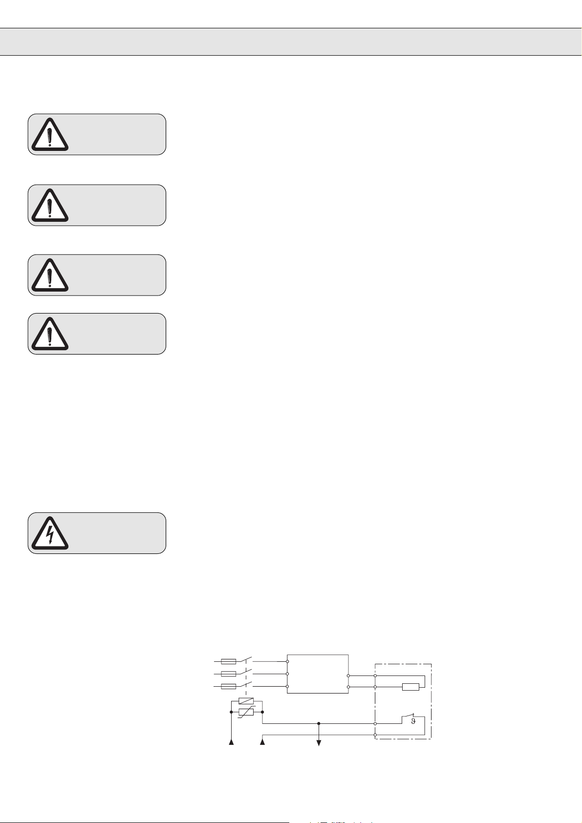
Fire hazard
It is imperative to monitor the braking resistance temperature switch so as to avoid a
braking resistance overload. To do so, connect the sensor to T1 (OH) and T2 (OH) as
described in Part 2 of the instructions. If the braking transistor is defective, however, this
measure will not suffice to prevent an extreme overload and acute danger of fire. This
type of danger can only be averted by disconnecting the mains voltage (see diagram).
Overloads may be caused by:
• the ramps being too short or the operating time too long
• incorrect dimensioning of the braking resistance
• the input voltage being too high
• defect of the braking transistor in the inverter or braking module
Frequency inverter / servo
L1
L2
L3
U
230 or 24 V AC/DC
drive
L1
L2
(+) PA
L3
at 24 V AC/DC
check tripping
PB
PA
PB
OH1
OH2
Braking resistance
with temperature
switch
Page 7
ANTRIEBSTECHNIK
RCD
(FI-Protective
Switch)
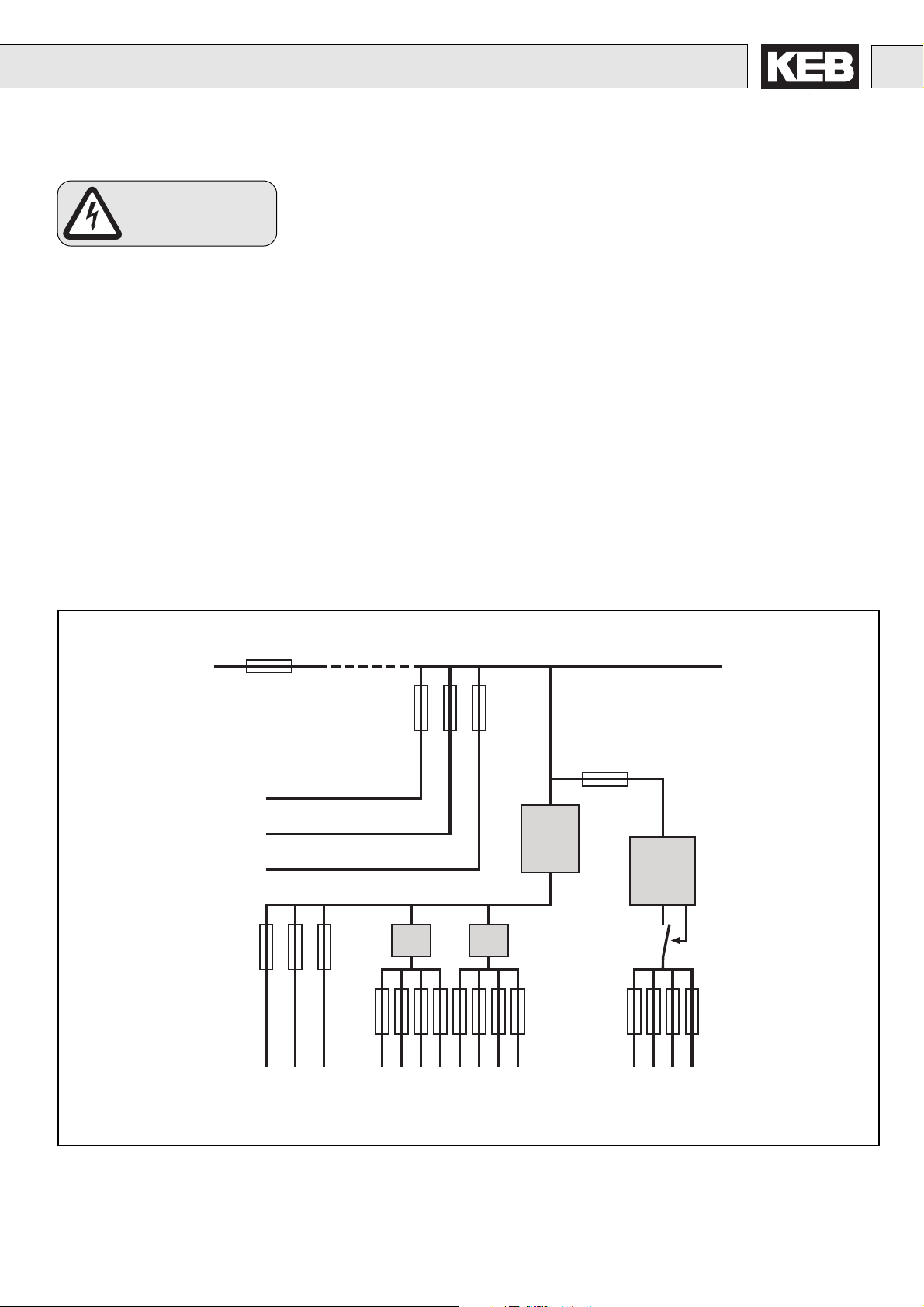
If personnel protection is required during installation of the system the frequency
inverters must be protected according to EN 50178:
• 1-phase inverters by RCD type A (pulse-current sensitive FI’s) or type B (all-current
sensitive FI’s)
• 3-phase inverters (with B6 bridge-connected rectifier) by RCMA’s with separation
(used privileged) or RCD’s type B (all-current sensitive FI’s)
The tripping current should be 300mA or more, in order to avoid a premature triggering
of the inverter by discharge currents (about 200mA).
Dependent on the load, the length of the motor cable and the use of a radio interference
filter, substantially higher leakage current can occur.
The connection instructions from the manufacturer and the valid local reqirements must
be observed.
Dependent on the available mains form (TN, IT, TT) further protective measures are
necessary in accordance with VDE Part 410 (Part 4; Chapter 41). For example, with TNmains this protection is made with overcurrent protective devices. With IT-mains it is
insulation monitoring with a pulse-code measuring method. A protective separation can
be used with all mains forms as long as the required power and cable lengths permit this.
The person setting up the unit must present proof of compatibility before installing the
inverter!
Circuit diagram of low voltage distribution (principle of the protective elements)
Mains
to further
sub-divisions
Outlet 1
Outlet 2
Outlet 3
Level 1
Level 2
Typ
A
Typ
A
To further consumers that do not
prevent the tripping of the FI.
RCD
Typ A
sel. T
RCMA/
RCD
Typ B
Isolator
in accordance with
EN 60947-2
To the consumers not
compatible with FI.
17
Page 8
2.6 Operating
Instructions
Damage to property
and injury to
persons
Before putting the unit into operation, check terminals and screw connections for tight
fit and put back all pertaining covers.
Observe the following instructions to avoid damage to the frequency inverter / servo
drive as well as subsequent damage and injury to persons:
• Install circuit braker between power supply and frequency inverter / servo drive so
that it is possible to switch the device off independently.
• In the case of separate drives, switching between motor and frequency inverter /
servo drive is prohibited during operation as this may trigger the protection gear of
the device. If you cannot avoid switching, consult KEB regarding protective measures.
Connecting and disconnecting is permissible with multiple motor drives if at least 1
motor is running during the switch-over process. Dimension the frequency inverter /
servo drive to match the occurring starting currents.
• If the motor is still running during a frequency inverter / servo drive restart (mains
on) -e.g. due to large gyrating masses – the RPM search or DC braking function
must be activated.
• When switching between motor and frequency inverter / servo drive, the RPM search
function must be activated. The function may only be triggered after closing the
motor contactor.
• Modified programming of the frequency inverter / servo drive (variation of works
setting), should be checked again before putting the device into operation.
!Misadjustments may cause unintentional drive performance!
• Should malfunctions or defects regarding the frequency inverter / servo drive occur
despite observance of the instructions concerning connection and operation, these
may cause undefined operating statuses. Activation of software-supported protective
functions such as limit switch function, correct switching of a brake or correct reactions
to set value specifications is no longer guaranteed.
• Securing a unit solely with software-supported functions does not suffice. It is imperative to install external protective measures that are independent of the frequency
inverter / servo drive.
Automatic
Restart
Cyclic activation
and deactivation
Conditionally
Short-Circuit
Proof
Inverters/servo drives may be set, dependent on type, to restart automatically following
a fault stoppage (e.g. Undervoltage Error), when the fault conditions clear. System
design must take this into account, if appropriate, and additional monitoring or protective
features added where necessary.
With applications requiring the frequency inverter / servo drive to be switched on and
off cyclically, maintain an off-time of at least 5 min. If you require shorter cycle times
please contact KEB.
The frequency inverters / servo drives are conditionally short-circuit proof (EN 50178).
After resetting the internal protection devices, the function as directed is guaranteed.
Exceptions:
• If an earth-leakage fault or short-circuit often occurs at the output, this can lead to a
defect in the unit.
• If a short-circuit occurs during regenerative operation (2nd or 4th quadrant, feedback
into the intermediate circuit), this can lead to a defect in the unit.
18
Page 9
ANTRIEBSTECHNIK
3. EMC
Fundamentals
3.1 General
3.2 Installation
PE
L1, L2, L3
1
Frequency inverters / servo drives represent electrical equipment designed for use in
industrial and commercial units. In accordance with the EMC directive 89/336/EEC, it
is not obligatory to mark these devices as they represent components to be further
processed by the respective machine and unit manufacturer and are not operable
independently according to the EMC directive. The person installing / operating the
machine / unit is obliged to proove the protective measures demanded by the EMC
directive are complied with. The prescribed ratings can usually be complied with when
using the radio interference voltage filters specified by KEB, and when observing the
following measures and installation guidelines.
The KEB frequency inverter / servo drive is designed to be used in the second
environment as defined in EN 61800-3 (unit with its own supply transformer).
Take additional measures when using it in the first environment (residential and
commercial area connected to public low-voltage mains)!
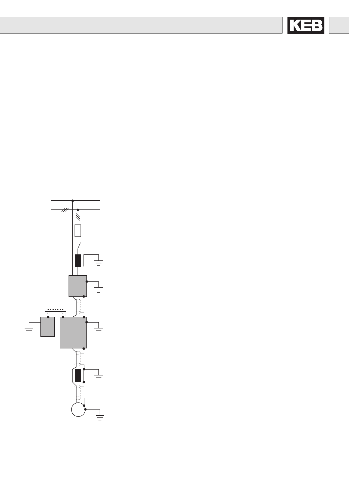
; Install the cabinet or system correctly.
; To avoid coupled-in noise, separate
• mains / supply lines
• motor lines from inverters / servo actuator
• control and data lines (low-voltage level < 48V)
and leave a space of at least 15 cm between them when installing.
2
3
4
5
6
M
7
1. Mains Fuse
2. Main Protection
3. Line Reactor
4. Interference Suppression Filter
(if not already installed)
5. Inverter with Braking Resistor
6. Motor Choke or Output Filter
7. Motor
3~
; In order to maintain low-resistance high frequency connections, earthing and
shielding, as well as other metallic connections (e.g. mounting plate, installed units)
must be in metal-to-metal contact with the mounting plate, over as large an area
as possible. Use earthing and equipotential lines with a section as large as possible
(min. 10mm2) or use thick earthing strips.
; Only use shielded cable with copper or tin-plated braid, since steel braid is not
suitable for high frequency ranges. The screen must always be installed on the
compensating rail and fastened with clips or guided through the wall of the housing
with metal screw connections. Do not elongate the screen end (pigtails) with
individual conductors!
; If external interference suppression filters are used, then these must be installed
as close as possible to (<30cm from) the interference source and in metal-to-metal
contact with the mouting plate, over as large an area as possible.
; Always equip inductive control elements (contactors, relays etc.) with suppressors
such as varistors, RC-elements or damping diodes.
; All connections must be kept as short as possible and as close as possible to the
earth, as free floating lines work as active and passive aerials.
; Keep connection cables straight (do not bundle). Install a non-assigned wire on
both sides of the protective conductor.
; The flow and return circuit must be twisted when the lines are not shielded, in order
to dampen common-mode noise.
; Further informations are found in the instruction manual part 2/3.
19
Page 10
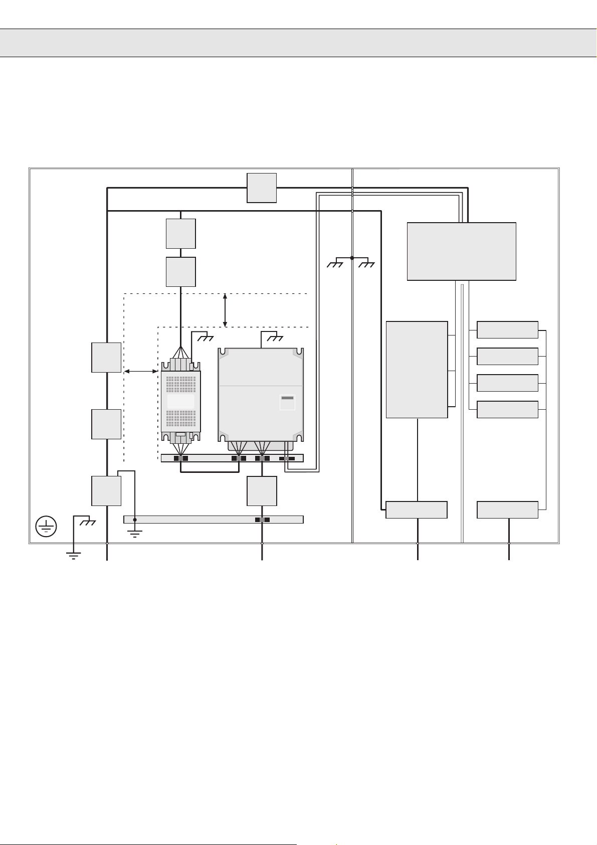
3.3 Installation of an EMC Conform Cabinet
Power Range Control Range
10
3
17
18
3
2
1
15 cm
4
15 cm
13
14
5
6
11
12
8
15 16
7
9
1. Mains input
2. Line contactor or main switch
3. Mains fuse
4. Power choke
5. Interference suppression filter
6. Frequency inverter / servo drive
7. Screen with clips
8. Motor choke / sinusoidal filter (option)
9. Motor feed line
20
10. Power pack
11. Control lines
12. AC-BUS
13. PLC / PC
14. Contactors / PKZ
15. 230V / 400V I/O
16. Logic I/O
17. Mounting plate is the common star point (peripheral unit)
18. Equipotential bonding with earthing of building
Page 11

ANTRIEBSTECHNIK
3.4 Explanations
; A system should be broadly separated into power section and control section,
whether comprising a single enclosure or multiple enclosures. It is recommended
that a screen wall is installed between the two sections because of the radiated
noise from the power section. This screen must be in good metal-to-metal contact
with the mouting plate (remove galvanized or lacquer finish), over as large an area
as possible.
; The installed inverter and a superposed interference suppression filter must form
a unit, i.e. they must, for example, be connected to each other without an insulating
layer of lacquer and cover the mounting plate evenly.
; The connecting line between interference suppression filter and inverter should be
a shielded line installed on both sides and usually be no longer than 30 cm.
; The mounting plate of the inverter must be seen as the neutral point for the entire
earthing and shield connection in the machine or system. If the motor or other
system parts lead to disturbances, then the HF-connection of these elements is
bad. In this case equipotential bonding must be done.
; A good connection of the shield onto the motor terminal box is only given, when the
terminal box is made out of metal, and a metal cable gland is used to connect the
screen. When using a plastic box, provide the shield without elongation with a cable
lug and connect directly with the earthing point.
; The leakage currents in the circuit increase when interference suppression filters
are used. Since these lie above the 3,5mA threshold, one of the following conditions
must be met:
• Protective conductor section at least 10 mm² copper
• Monitoring of the protective conductor by a device that independently switches
off under fault conditions.
• Install a second conductor electrically parallel to the protective conductor via
separate terminals.
; Place consumers generating electric or magnetic fields or affecting the voltage
supply as far away as possible and take measures to suppress the interference.
; The service life of the frequency converter / servo drive with intermediate voltage
circuit depends on the current load of the electrolytic capacitors in the intermediate
circuit. The use of mains chokes can increase the service life of the condensators
to a considerable extent, especially when connecting to „hard“ power systems or
when under permanent drive load (continuous duty).
For continuous duty (S1) drives with a medium duty of >60% , KEB recommends
the use of mains chokes with a terminal voltage (Uk) of 4%.
The term “hard” mains can be defined as follows:
The inverter’s nominal power (Sn) is very low compared to the nodal point power
(Smains) .
k = Smains / Sn >> 200 e.g. Sn = 6.6 kVA 12.F4
Smains = 2 MVA supply transformer
––> k = 330
––> Choke required
; When using a mains choke, it should usually be mounted on the mains side of the
interference suppression filter.
21
Page 12
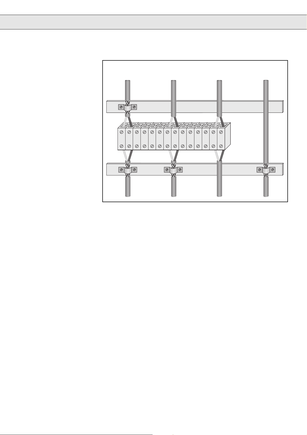
3.5 Connection of the
Control Lines
Notes:
Line from
encoder
Analog
line
Non-shielded
control signal
Data line
4. CE-Marking
5. Manufacturer´s
Declaration
• Connect the screen schiene with the stripped mounting plate covering as much
space as possible and do not use as strain relief.
• The shield from the digital signal lines, which is not connected via terminals,
must be clamped to the screen bus, both at the cabinet entrance and near the
inverter, in order to decrease the screen impedance.
• If digital signal lines are connected via terminals, the screen must be clamped to
the screen bus before and after the terminals.
• If a screen bus is used near the inverter (max 20 cm distance), then the screen
no longer needs to be connected to the inverter.
• If the shield is earthed with a single charger, then the interference derivation
deteriorates by 70%.
• Metal copper pipe clips are suitable as a shield connection.
• When using non-shielded signal lines, they should always be installed as a twisted
pair with a forward and return circuit.
CE marked frequency inverter and servo drives were developed and manufactured
to comply with the regulations of the Low-Voltage Directive 73/23/EEC.
The applied standards are listed in the technical documentation part 2.
A manufacturer declaration in accordance with 89/392/EEC can be provided by KEB
if needed.
22
Page 13

Page 14

Karl E. Brinkmann GmbH
Försterweg 36 - 38 • D - 32683 Barntrup
Telefon 00 49 / 52 63 / 4 01 - 0 • Fax 00 49 / 52 63 / 4 01 - 1 16
Internet: www.keb.de • E-mail: [email protected]
KEB Antriebstechnik GmbH & Co. KG
Telefon 0049 / 37 72 / 67 - 0 • Telefax 0049 / 37 72 /67 - 2 81
Tel.: 0043 / 7243 / 53586 - 0 • FAX: 0043 / 7243 / 53586 - 21
Wildbacher Str. 5 • D - 08289 Schneeberg
E-mail: [email protected]
KEB Antriebstechnik Austria GmbH
Ritzstraße 8 • A - 4614 Marchtrenk
Kostelni 32/1226 • CZ - 370 04 Ceské Budejovice
Tel.: 00420 / 38 / 731 92 23 • FAX: 00420 / 38 / 733 06 97
E-mail: [email protected]
Herenveld 2 • B - 9500 Geraadsbergen
Tel.: 0032 / 5443 / 7860 • FAX: 0032 / 5443 / 7898
Xianxia Road 299 • CHN - 200051 Shanghai
Tel.: 0086 / 21 / 62350922 • FAX: 0086 / 21 / 62350015
Internet: www.keb-cn.com • E-mail: [email protected]
Z.I. de la Croix St. Nicolas • 14, rue Gustave Eiffel
Tél.: 0033 / 1 / 49620101 • FAX: 0033 / 1 / 45767495
6 Chieftain Buisiness Park, Morris Close
Park Farm, Wellingborough, GB - Northants, NN8 6 XF
Tel.: 0044 / 1933 / 402220 • FAX: 0044 / 1933 / 400724
Internet: www.keb-uk.co.uk • E-mail: [email protected]
Via Newton, 2 • I - 20019 Settimo Milanese (Milano)
Tel.: 0039 / 02 / 33500782 • FAX: 0039 / 02 / 33500790
Internet: www.keb.it • E-mail: [email protected]
Tel.: 0081 / 233 / 29 / 2800 • FAX: 0081 / 233 / 29 / 2802
KEB Antriebstechnik
E-mail: [email protected]
KEB China
Société Française KEB
F - 94510 LA QUEUE EN BRIE
E-mail: [email protected]
KEB (UK) Ltd.
KEB Italia S.r.l.
KEB - YAMAKYU Ltd.
711 Fukudayama, Fukuda
J - Shinjo-Shi, Yamagata 996 - 0053
E-mail: [email protected]
1F, No.19-5, Shi Chou Rd., Tounan Town
KEB Taiwan Ltd.
R.O.C. - Yin-Lin Hsian / Taiwan
Tel.: 00886 / 5 / 5964242 • FAX: 00886 / 5 / 5964240
E-mail: [email protected]
KEBCO Inc.
1335 Mendota Heights Road
USA - Mendota Heights, MN 55120
Tel.: 001 / 651 / 4546162 • FAX: 001 / 651 / 4546198
Internet: www.kebco.com • E-mail: [email protected]
© KEB 00.00.EMV-K003 06/2001
 Loading...