


COMBIVERT
D
GB
Allgemeine
EMV- und Sicherheitshinweise im
Downloadbereich
unter www.keb.de
beachten !
The general
EMC and safety
directions at
www.keb.de have
to be observed !
Mat.No. Rev.
00F5S1M-KA03 1G
Installationsanleitung Gehäuse A
Installation Manual Housing A


D - 3
D
D - 4
Diese Anleitung beschreibt den KEB COMBIVERT F5. Im Einzelnen wird auf den Einbau, die Anschlussmöglichkeiten sowie die grundlegende Bedienung eingegangen. Aufgrund der vielfältigen
Einsatz- und Programmiermöglichkeiten ist der anwendungsspezische Anschluss- bzw. Verdrahtungsplan, die Parametereinstellung sowie Hinweise zur Inbetriebnahme der Dokumentation des
Maschinenherstellers zu entnehmen.
Eine Aufstellung von Anleitungen und Dokumenten zur Unterstützung für Konstruktion, Dokumentation und Service sind am Ende dieser Anleitung zusammengefasst. Den Sicherheits- und Warnhinweisen in dieser Anleitung sowie in weiterer Dokumentation ist für einen sicheren Betrieb unbedingt Folge zu leisten. Die Nichtbeachtung der Sicherheitshinweise führt zum Verlust jeglicher
Schadensersatzansprüche. Die in dieser Anleitung aufgeführten Sicherheits- und Warnhinweise
erheben keinen Anspruch auf Vollständigkeit. Die Karl E. Brinkmann GmbH behält sich das Recht
vor, Spezikationen und technische Daten ohne vorherige Benachrichtigung zu ändern, bzw. anzupassen. Die verwendeten Piktogramme entsprechen folgender Bedeutung:
Gefahr
Wird verwendet, wenn Leben oder Gesundheit des Benutzers
gefährdet sind oder erheblicher Sachschaden auftreten kann.
Warnung
Vorsicht
Achtung
Wird verwendet, wenn eine Maßnahme für den sicheren und störungsfreien Betrieb erforderlich ist.
unbedingt
beachten
Information
Wird verwendet, wenn eine Maßnahme die Handhabung oder
Bedienung des Gerätes vereinfacht.
Hilfe
Tip
Die in den technischen Unterlagen enthaltenen Informationen, sowie etwaige anwendungsspezische Beratung in Wort, Schrift und durch Versuche, erfolgen nach bestem Wissen und Kenntnissen über die Applikation. Sie gelten jedoch nur als unverbindliche Hinweise. Dies gilt auch in
Bezug auf eine etwaige Verletzung von Schutzrechten Dritter.
Eine Prüfung unserer Geräte im Hinblick auf ihre Eignung für den beabsichtigten Einsatz hat
jedoch generell durch den Anwender zu erfolgen. Prüfungen sind insbesondere auch dann erforderlich, wenn Änderungen durchgeführt wurden, die der Weiterentwicklung oder der Anpassung
unserer Produkte (Hardware, Software, oder Downloadlisten) an die Applikationen dienen. Prüfungen sind komplett zu wiederholen, auch wenn nur Teile von Hardware, Software, oder Down-
loadlisten modiziert worden sind. Originalersatzteile und vom Hersteller autorisiertes Zubehör
dienen der Sicherheit. Die Verwendung anderer Teile hebt die Haftung für daraus resultierende
Schäden auf.
Der Einsatz und die Verwendung unserer Geräte in den Zielprodukten erfolgt außerhalb unserer
Kontrollmöglichkeiten und liegt daher ausschließlich im Verantwortungsbereich des Anwenders.
Reparaturen dürfen nur vom Hersteller bzw. durch von ihm autorisierte Reparaturstellen vorgenommen werden. Unbefugtes Öffnen und unsachgemäße Eingriffe können zu Körperverletzungen
bzw. Sachschäden führen und haben den Verlust der Gewährleistung zur Folge.

D - 5
Inhaltsverzeichnis
1. Sicherheits- und Anwendungshin-
weise..................................................... 6
2. Produktbeschreibung ......................... 7
2.1 Verwendungszweck............................... 7
2.2 Geräteidentikation ............................... 7
2.3 Technische Daten .................................. 8
2.4 Abmessungen und Anschlüsse ........... 10
3. Einbau und Anschluss .......................11
3.1 Schaltschrankeinbau ............................11
3.2 EMV-gerechte Verdrahtung ..................11
3.3 Anschluss des Leistungsteil ................ 12
3.3.1 Verdrahtungshinweise ......................... 12
3.3.2 Klemmleiste X1A ................................. 12
3.3.3 Netzanschluss ..................................... 13
3.3.4 Motoranschluss mit Klemmleiste X1B . 13
3.3.5 Anschluss der Temperaturerfassung ... 14
3.3.6 Anschluss eines Bremswiderstandes mit
Temperaturüberwachung gemäß UL ... 15
3.4 Geberinterfaceanschluss..................... 15
3.4.1 Resolveranschluss bei KEB Motoren
über Buchse X3A................................. 15
3.4.2 Inkrementalgebereingang / -nachbildung
X3B...................................................... 16
3.5 Steuerkarte Servo ............................... 17
3.5.1 Steuerklemmleiste X2A ....................... 17
3.5.2 Anschluss der Steuerklemmleiste ....... 18
4. Bedienung des Gerätes .................... 19
4.1 Zubehör zur Bedienung ....................... 19
4.1.1 Ohne Operator mit HSP5-Servicekabel ..
19
4.1.2 Digitaloperator (Artikelnummer 00F5060-
1000) ................................................... 19
4.1.3 Interfaceoperator (Artikelnummer
00F5060-2000) .................................... 19
4.1.4 Fernbedienung ................................... 20
4.1.5 Weitere Operatoren ............................. 20
4.2 Tastaturbedienung ............................... 20
4.2.1 Parameternummern und /-werte ......... 20
4.2.2 Rücksetzen von Fehlermeldungen ...... 21
4.2.3 Passworteingabe ................................. 21
5.3 Parameterbeschreibung für F5-Servo . 22
B. Anhang B ........................................... 26
B.1 CE-Kennzeichnung ............................. 26
B.2 UL-Kennzeichnung .............................. 26
B.3 Weitere Anleitungen ............................ 27

D - 6
Produktbeschreibung
2. Produktbeschreibung
2.1 Verwendungszweck
Der digitale Servosteller KEB COMBIVERT F5-SERVO dient ausschließlich zur Steuerung
und Regelung von Sychron-Servomotoren. Der Betrieb anderer elektrischer Verbraucher ist
untersagt und kann zur Zerstörung der Geräte führen.
Die Steller sind bei Auslieferung auf die von KEB gelieferten Servomotoren abgestimmt.
Servosteller sind Komponenten, die zum Einbau in elektrische Anlagen oder Maschinen
bestimmt sind.
2.2 Geräteidentikation
A6 . F5 . S 3 A - 3 4 2 A
Motorkühlung
0: Selbstkühlung 1: Fremdkühlung
A: wie 0; lackiert B: wie 1; lackiert
Geberinterface
2: Resolver
Motordrehzahl
1: 1500 1/min 2: 2000 1/min
3: 3000 1/min 4: 4000 1/min
6: 6000 1/min
Eingangskennung
2: 1/3-ph. 230 V AC/DC
3: 3-ph. 400 V AC/DC
Gehäuseausführung A
Zubehör
1: GTR7 3: GTR7 und Filter
Steuerungstyp
S: SERVO
Baureihe F5
Motorbauform / Motorkennung / Motorgröße
A0…GH: Standardsysteme
Sonstige: Kunden- oder Spezialversion

D - 7
2.3 Technische Daten
Produktbeschreibung
1)
Dieser Wert führt zum Ansprechen der Hardwarestromgrenze. Die maximale Momentengrenze sollte immer
unterhalb liegen, da sonst keine Regelung mehr möglich ist.
2)
Die Kühlkörperverlustleistung setzt sich aus den Verlusten von Endstufe und Gleichrichter zusammen. Bei DC-
Geräten entfällt die Gleichrichterverlustleistung. Bei Flat-Rear-Geräten muss der angegebene Wert über die
Montageäche abgeleitet werden.
3)
Bei Nennspannungen ab 460 V ist der Nennstrom mit Faktor 0,86 zu multiplizieren. Achtung, bei einer Eingangs-
bemessungsspannung von 480 Vac darf kein Bremswiderstand angeschlossen werden.
4)
Mit Unterbaulter bei Einhaltung der Klasse C1 gemäß EN 61800-3.
5)
Bei Verwendung von Motorschutzschaltern (E-MMC/ Type E - Manual Motor Controller nach UL508 / Class NKJH)
als Absicherung sind gemäß Abnahme nach UL nur folgende Typen zugelassen:
Hersteller UL - Datei Typ Erforderlicher Netzanschlussadapter
Siemens E 156943
3RV1021-1xA10 3RV1928-1H
3RV1031-4xA10 –
Servogröße 05 07 07 09
Gehäusegröße A A A A
Phasen 1 3 1 3 3 3
Eingangsbemessungsspannung [V] 230 400
Ausgangsbemessungsleistung [kVA] 0,9 1,6 1,8 2,8
Ausgangsbemessungsstrom [A] 2,3 4 2,6 4,1
Stillstandsdauerstrom [A] 2,5 4,4 2,9 4,5
Max. Kurzzeitgrenzstrom
1)
[A] 4,6 8 5,2 8,2
OC-Auslösestrom [A] 5,5 9,6 6,2 9,8
Eingangsbemessungsstrom [A] 4,6 3,2 8 5,6 3,6 6
Bemessungsschaltfrequenz [kHz] 8 8 8 4
Max. Schaltfrequenz [kHz] 8 8 8 8
Verlustleistung bei Bemessungsbetrieb [W] 38 35 55 50 65 65
Kühlkörperverlustleistung
2)
[W] 28 25 45 40 55 55
Kühlkörperverlustleistung (DC)
2)
[W] 25 22 40 35 52 50
Minimaler Bremswiderstand [Ω] 60 60 110 110
Typischer Bremswiderstand [Ω] 160 82 210 160
Maximaler Bremsstrom [A] 7 7 7,5 7,5
Netzspannung U
N
3)
[V] 180…260 ±0 305…528 ±0
Netzfrequenz [Hz] 50…60 ±2
Ausgangsspannung [V] 3 x 0…U
N
Ausgangsfrequenz [Hz] 0…400
Max. Motorleitungslänge (geschirmt)
4)
[m] 30
Max. Motorleitungslänge (geschirmt) [m] 50
Bei Verwendung in den USA
Max. Netzsicherung Type RK5 [A] 10 6 15 10 6 10
Max. Einstellstrom mit Motorschutzschalter
5)
[A] 10 6,3 16 10 10 10

D - 8
ABB Stotz E 195536
MS325-xx S3-M3
MS450-xx –
Rockwell / Allen Bradley E 205542
140M-C2E-Bxx or Cxx –
140M-F8E-Cxx –
Moeller E 123500 PKZM0-xxE (nur bis 25 A) BK25/3 - PKZ0-E
Für x oder xx ist die o.a. Strombelastbarkeit oder der korrespondierende Buchstabe einzugeben.
Der Einsatz ist nur in sternpunktförmig geerdetem Netz mit 480/277 V zulässig.
Aufstellhöhe maximal 2000 m über NN. Bei Aufstellhöhen über 1000 m ist eine
Leistungsreduzierung von 1 % pro 100 m zu berücksichtigen.
Überlastkennlinie (OL-Funktion)
0
50
100
150
200
250
300
s
100 120 140 160 180 200
%

D - 9
Produktbeschreibung
2.4 Abmessungen und Anschlüsse
PE
L1
L2
L3
++
--
PE
L1
N/L2
L3
++
--
Wa
Ein Fe
schutz s
ist als allei
Schutzmaßna
nicht zulÌässig
Die Ko
entlad
beträg
T2
T1
PB
PA
WVU
PE
185
175
144
158
76
5
U, V, W Anschluss für Servomotor
PA, PB Anschluss Bremswiderstand
T1, T2 Anschluss für Temperatursensor/-schalter
L1, N/L2, L3 1/3-phasiger Netzanschluss (230 V-Klasse)
L1, L2, L3 3-phasiger Netzanschluss (400 V-Klasse)
++, -- Gleichspannungsein-/ausgang für DC-Versorgungungsnetze
250...370 V DC (230 V-Klasse)
420...720 V DC (400 V-Klasse)
PE Anschluss für Schutzleiter
Eingangsspannung beachten, da 230 V (1/3-phasig) und 400 V-Klasse (3-phasig)
möglich !
Inkrementalgebernachb. X3B
Resolver X3A
X4A
X2A
X1B
230 V-Klasse X1A
mit Operator
mit Blindabdeckung
400 V-Klasse X1A
191 (mit Klemmleisten)

D - 10
1. Allgemein
Während des Betriebes können Antriebsstromrichter ihrer
Schutzart entsprechend spannungsführende, blanke, gegebenenfalls auch bewegliche oder rotierende Teile, sowie heiße
Oberächen besitzen.
Bei unzulässigem Entfernen der erforderlichen Abdeckung,
bei unsachgemäßem Einsatz, bei falscher Installation oder
Bedienung, besteht die Gefahr von schweren Personen- oder
Sachschäden.
Weitere Informationen sind der Dokumentation zu entnehmen.
Alle Arbeiten zum Transport, zur Installation und Inbetriebnahme
sowie zur Instandhaltung sind von qualiziertem Fachpersonal
auszuführen (IEC 364 bzw. CENELEC HD 384 oder DIN VDE
0100 und IECReport 664 oder DIN VDE 0110 und nationale
Unfallverhütungsvorschriften beachten).
Qualiziertes Fachpersonal im Sinne dieser grundsätzlichen
Sicherheitshinweise sind Personen, die mit Aufstellung, Montage,
Inbetriebsetzung und Betrieb des Produktes vertraut sind und über
die ihrer Tätigkeit entsprechenden Qualikationen verfügen.
2. Bestimmungsgemäße Verwendung
Antriebsstromrichter sind Komponenten, die zum Einbau in
elektrische Anlagen oder Maschinen bestimmt sind.
Bei Einbau in Maschinen ist die Inbetriebnahme der Antriebsstromrichter (d.h. die Aufnahme des bestimmungsgemäßen Betriebes)
solange untersagt, bis festgestellt wurde, dass die Maschine den
Bestimmungen der EG-Richtlinie 2006/42/EG (Maschinenrichtlinie) entspricht; EN 60204 ist zu beachten.
Die Antriebsstromrichter erfüllen die Anforderungen der Niederspannungsrichtlinie 2006/95/EG. Die harmonisierten Normen
der Reihe EN 61800-5-1 werden für die Antriebsstromrichter
angewendet.
Die technischen Daten sowie die Angaben zu Anschlussbedingungen sind dem Leistungsschild und der Dokumentation zu
entnehmen und unbedingt einzuhalten.
3. Transport, Einlagerung
Die Hinweise für Transport, Lagerung und sachgemäße Handhabung sind zu beachten.
Klimatische Bedingungen sind entsprechend EN 61800-5-1
einzuhalten.
4. Aufstellung
Die Aufstellung und Kühlung der Geräte muss entsprechend den
Vorschriften der zugehörigen Dokumentation erfolgen.
Die Antriebsstromrichter sind vor unzulässiger Beanspruchung zu
schützen. Insbesondere dürfen bei Transport und Handhabung
keine Bauelemente verbogen und/oder Isolationsabstände verändert werden. Die Berührung elektronischer Bauelemente und
Kontakte ist zu vermeiden.
Antriebsstromrichter enthalten elektrostatisch gefährdete
Bauelemente, die leicht durch unsachgemäße Behandlung beschädigt werden können. Elektrische Komponenten dürfen nicht
mechanisch beschädigt oder zerstört werden (unter Umständen
Gesundheitsgefährdung!).
5. Elektrischer Anschluss
Bei Arbeiten an unter Spannung stehenden Antriebsstromrichtern
sind die geltenden nationalen Unfallverhütungsvorschriften (z.B.
VBG 4) zu beachten.
Die elektrische Installation ist nach den einschlägigen Vorschriften
durchzuführen (z.B. Leitungsquerschnitte, Absicherungen, Schutzleiteranbindung). Weitere Informationen sind der Dokumentation
zu entnehmen.
Hinweise für die EMV-gerechte Installation - wie Schirmung,
Erdung, Anordnung von Filtern und Verlegung der Leitungen
- benden sich in der Dokumentation der Antriebsstromrichter.
Diese Hinweise sind auch bei CE gekennzeichneten Antriebsstromrichtern stets zu beachten. Die Einhaltung der durch die
EMV-Gesetzgebung geforderten Grenzwerte liegt in der Verantwortung des Herstellers der Anlage oder Maschine.
6. Betrieb
Anlagen, in die Antriebsstromrichter eingebaut sind, müssen
ggf. mit zusätzlichen Überwachungs- und Schutzeinrichtungen
gemäß den jeweils gültigen Sicherheitsbestimmungen, z.B. Gesetz
über technische Arbeitsmittel, Unfallverhütungsvorschriften usw.
ausgerüstet werden. Veränderungen der Antriebsstromrichter mit
der Bediensoftware sind gestattet.
Nach dem Trennen der Antriebsstromrichter von der Versorgungsspannung dürfen spannungsführende Geräteteile und Leistungsanschlüsse wegen möglicherweise aufgeladener Kondensatoren
nicht sofort berührt werden. Hierzu sind die entsprechenden
Hinweisschilder auf dem Antriebsstromrichter zu beachten.
Während des Betriebes sind alle Abdeckungen und Türen
geschlossen zu halten.
7. Wartung und Instandhaltung
Die Dokumentation des Herstellers ist zu beachten.
Diese Sicherheitshinweise sind aufzubewahren!
Sicherheits- und Anwendungshinweise
für Antriebsstromrichter
(gemäß: Niederspannungsrichtlinie 2006/95/EG)
Wichtig, unbedingt lesen
1. Sicherheits- und Anwendungshinweise
D - 11
Einbau und Anschluss
3. Einbau und Anschluss
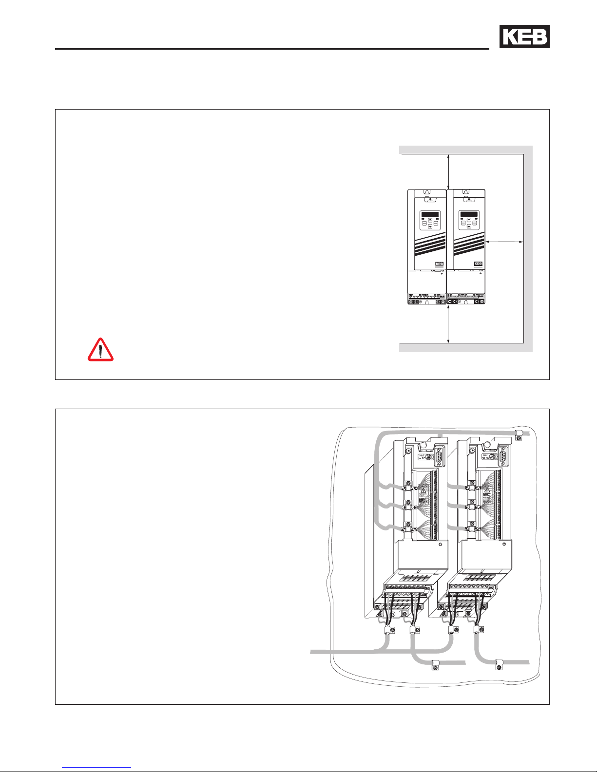
3.1 Schaltschrankeinbau
3.2 EMV-gerechte Verdrahtung
Einbaulage und Mindestabstände
150 mm
30 mm
100 mm
START
STOP
FUNC.
SPEED
ENTER
F/R
ANTRIEBSTECHNIK
START
STOP
FUNC.
SPEED
ENTER
F/R
ANTRIEBSTECHNIK
6 inch
1 inch
4 inch
Schutzart (EN 60529): IP20
Betriebstemperatur: -10…45 °C (14…113 °F)
Lagerungstemperatur: -25…70 °C (-13…158 °F)
max. Kühlkörpertemperatur:
Größe 05/230 V und 07-09/400 V 90 °C (194 °F)
Größe 07/230 V 82 °C (180 °F)
Klimakategorie (EN 60721-3-3): 3K3
Umgebung (IEC 664-1): Verschmutzungsgrad 2
Vibration/Schock gemäß: German. Lloyd; EN 50155
Die Flat-Rear-Ausführung erfordert Kühlmaßnahmen
durch den Maschinenbauer. Dies kann im besten
Fall keine weitere Maßnahme (z.B. bei Taktbetrieb
mit Standzeit) bis zur Abführung der gesamten,
angegebenen Verlustleistung bei Nennbetrieb sein.
COMBIVERT vor aggressiven Gasen und
Aerosolen schützen!
• Abschirmung von Motor- und Steuerleitungen
immer beidseitig und großächig auegen.
• Abstand zwischen Steuer- und Leistungslei-
tungen mindestens 10…20 cm (4…8 inch).
• Motor- und Netzleitung getrennt verlegen.
• Wenn nicht zu vermeiden, Steuer- und Leis-
tungsleitungen im rechten Winkel kreuzen.
• Alle Leitungen möglichst dicht an der Montageplatte verlegen - ideal im Metallkabelkanal.
• COMBIVERT gut leitend mit der Montageplatte montieren. Lack vorher entfernen.
Weitere Hinweise zur EMV - gerechten Ver-
drahtung nden Sie bei KEB im Internet.

D - 12
7
L1
L2
L3
++
--
E
Einbau und Anschluss
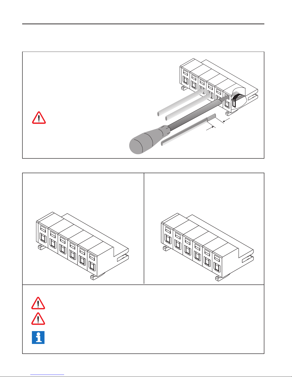
3.3 Anschluss des Leistungsteil
3.3.1 Verdrahtungshinweise
• Aderquerschnitt 1,5 mm²
• 7 mm abisolieren
• Wahlweise Verwendung von Aderendhül-
sen
• Nach Arretierung durch Entfernen des
Schraubendrehers - Kabel unbedingt auf
festen Sitz prüfen
Klemmleiste nur im spannungsfreiem
Zustand aufstecken / abziehen
3.3.2 Klemmleiste X1A
PE
L1
N/L2
L3
++
--
PE
L1
L2
L3
++
--
Klemmleiste X1A / 230 V-Klasse
• 230 V AC / 1-phasig (L1/N)
• 230 V AC / 3-phasig (L1, L2, L3)
• DC-Versorgung 250…370 V DC (++, --)
Klemmleiste X1A / 400 V-Klasse
• 400 V AC / 3-phasig (L1, L2, L3)
• DC-Versorgung 420…720 V DC (++, --)
Achten Sie unbedingt auf die Anschlussspannung des KEB COMBIVERT. Ein 230 V-
Gerät am 400 V-Netz wird sofort zerstört.
Vertauschen Sie niemals die Netz- und Motorleitung.
In einigen Ländern wird gefordert, dass die PE-Klemme direkt im Klemmkasten (nicht
über Montageplatte) angeschlossen wird.

D - 13
Einbau und Anschluss
++
--
L1
PE
N/L2
L3
L1
PE
N
Netzanschluss 230 V 1-phasig
++
--
L1
PE
N/L2
L3
L1
PE
L2
L3
++
--
L1
PE
L2
L3
L1
PE
L2
L3
++
--
L1
PE
N/L2
L3
+
-
++
--
L1
PE
L2
L3
+
-
1 x 230 V AC
3 x 1,5 mm²
Netzanschluss 230 V 3-phasig
3 x 230 V AC
4 x 1,5 mm²
Netzanschluss 400 V 3-phasig
3 x 400 V AC
4 x 1,5 mm²
DC-Anschluss 230 V-Klasse
250…370 V DC
2 x 1,5 mm²
DC-Anschluss 400 V-Klasse
2 x 1,5 mm²
420…720 V DC
3.3.3 Netzanschluss
3.3.4 Motoranschluss mit Klemmleiste X1B
T2
T1
PB
PA
WVU
PE
• PE Schutzleiter
• U, V, W Servomotor
• PA, PB Bremswiderstand
• T1, T2 Temperatursensor / -schalter
Absicherung
• Sicherung 10 A träge oder
Leistungsschutzschalter
• RCD (Fehlerstromschutzschalter) Typ A
oder Typ B
• bei DC-Versorgung auf den zulässigen
Spannungsbereich der Sicherungen achten

D - 14
Einbau und Anschluss
• Alle Steckverbindungen nur in spannungslosem Zustand stecken !
• Auf phasenrichtigen Anschluss des Motors achten !
• Motorleitung geschirmt
PTC
PTC
Bremse +
Bremse –
Motor
Leistungsstecker
A
B
C
D
1
2
3
4
PE
U
V
W
ext. Bremsspeisegerät
mit eigener Spannungsversorgung (optional)
Abschirmungen großächig auf der
Montageplatte und am Motorgehäuse auegen
gr/ge
1
2
3
7
8
5
6
Motorstecker
3.3.5 Anschluss der Temperaturerfassung
Motor-PTC
Sonstige
• Klemmen T1, T2
• Ansprechwiderstand 1,65…4 kΩ
• Rückstellwiderstand 0,75…1,65 kΩ
• Ausführung gemäß VDE 0660 Part 302
• Die Auswertung kann vom Maschinenbauer per Software aktiviert werden
• Anschlusskabel nicht zusammen mit Steuerkabeln verlegen
• Im Motorkabel nur mit doppelter Schirmung zulässig
• Relais K1 für Brandschutz im generatorischen Betrieb anschließen (siehe 3.3.6)
Stecker
PIN Nr.
Bezeichnung
Kabel
Ader Nr.
1 U 1
4 V 2
3 W 3
2 grün-gelb 4
A 5 5
B 6 6
C 7 7
D 8 8
D - 15
1
2
3
4
5
6
7
8
9
10
11
12
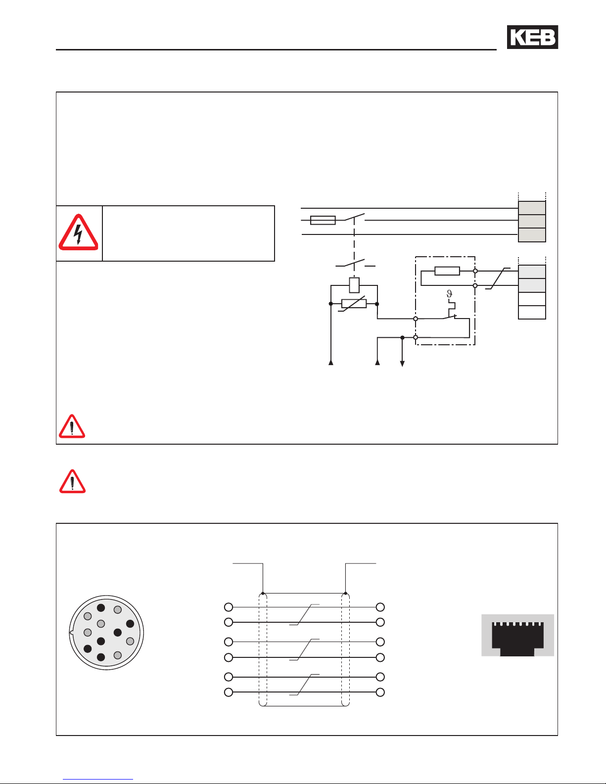
3.4.1 Resolveranschluss bei KEB Motoren über Buchse X3A
3.4 Geberinterfaceanschluss
18
Die Stecker dürfen nur bei ausgeschaltetem Frequenzumrichter und ausgeschalteter
Versorgungsspannung gezogen / gesteckt werden !
Motor
Resolverstecker
Buchse X3A
• Maximale Leitungslänge 50 m
3.3.6 Anschluss eines Bremswiderstandes mit Temperaturüberwachung gemäß UL
• PA, PB Anschluss für Bremswiderstand
• technische Daten (siehe Kapitel 2.3)
• bei Auslösung der Temperaturüberwachung wird die Eingangsspannung
weggeschaltet
• für zusätzlichen Schutz bei generatorischem Betrieb die Hilfskontakte 11 und 12 vom
Netzschütz K1 anschließen (siehe 3.3.5)
Bremswiderstände können sehr hohe Oberächentemperaturen entwickeln, daher möglichst
berührungssicher anbringen !
230 oder 24 V AC/DC
Ansteuerung
bei 24 V AC/DC
Kontrolle der Auslösung
Gehäuse
SIN- 1
SIN+ 10
REF- 5
REF+ 7
COS- 2
COS+ 11
Gehäuse
5 SIN- rot
4 SIN+ blau
6 REF- gelb
3 REF+ grün
8 COS- rosa
7 COS+ grau
Bei einer Eingangsbemessungsspannung von 480 Vac
darf kein Bremswiderstand
angeschlossen werden.

D - 16
18
3.4.2 Inkrementalgebereingang / -nachbildung X3B
Die Geberschnittstelle X3B ist umschaltbar von einer Inkrementalgebernachbildung auf
einen Inkrementalgebereingang. Die Strichzahl der Nachbildung beträgt bei Geräten mit
Resolverinterface immer 1024 Inkremente.
Maximale Eingangsfrequenz: < 300 kHz
Signale: RS 422 / 2 Spursignale und Nullsignal
max. Übertragungsstrecke: 50 m
freigegebene Geber: Kübler RS 422 Signale mit 10…30 V Versorgungsspannung
Die 12 V Versorgungsspannung an X3B ist
mit insgesamt 100 mA belastbar. Werden zur
Versorgung der Inkrementalgeber höhere
Spannungen / Ströme benötigt, muss der
Geber extern versorgt werden.
Buchse X3B
1
2
3
4
5
6
7
8
RJ45-Resolverstecker
frei 1
frei 2
grün 3
blau 4
rot 5
gelb 6
grau 7
rosa 8
frei
frei
REF+
SIN+
SINREF-
COS+
COS-
PIN Signal
1 12 V
2 GND
3 A+
4 B+
5 B6 A7 N+
8 N-

D - 17
Einbau und Anschluss
3.5 Steuerkarte Servo
3.5.1 Steuerklemmleiste X2A
1257810 11 12 13 24 25 2616 18 19 21 22
• Anzugsmoment 0,22…0,25 Nm (2 lb inches)
• Abgeschirmte/verdrillte Leitungen verwenden
• Schirm einseitig am Umrichter auf Erdpotential
legen
• Beim A-Servo ist keine NPN-Ansteuerung
möglich !
X2A
PIN Funktion Name Beschreibung
1 + Sollwerteingang 1 AN1+
Differenzspannungseingang
0…±10 V DC ^ 0…±Maximaldrehzahl, Ri = 55 kΩ
2 - Sollwerteingang 1 AN1-
5 Analogausgang
AN
OUT1
Programmierbarer Analogausgang 0…±10 V DC/ 5 mA.
Funktion wird vom Maschinenbauer festgelegt
7 +10V Ausgang CRF
Referenzspannungsausgang für Sollwertpotentiometer
(+10 V DC / max. 4 mA)
8 Analoge Masse COM Masse für analoge Ein- und Ausgänge
10 Progr. Eingang 1 I1 Die Funktion der programmierbaren Eingänge wird vom
Maschinenbauer festgelegt.
Schaltspannung 13…30 V DC ±0 % geglättet
Ri=2,1 kΩ
11 Progr. Eingang 2 I2
12 Progr. Eingang 3 I3
13 Progr. Eingang 4 I4
16
Speisespannung
Treiberstufe
ST
Versorgung der Treiberstufe
Dieser Eingang muss mit einer externen Spannung von
20…30 V DC ±0 % / 0,2 A (U
BR
max. 3,6 Vss) versorgt
werden. Beim Wegschalten dieser Spannung wird ein
Fehlerreset durchgeführt
18 Transistorausgang 1 O1 Programmierbare Digitalausgänge
Belastbarkeit für beide Ausgänge maximal 50 mA.
Funktion wird vom Maschinenbauer festgelegt
19 Transistorausgang 2 O2
21
Speisespannung
Steuerkarte
Uin
Spannungsversorgung der Steuerkarte
Dieser Eingang muss mit einer externen Spannung
von 20…30 V DC ±0 % / 0,8 A (U
BR
max. 3,6 Vss)
versorgt werden. Durch die getrennte Versorgung
kann die Steuerung auch bei abgeschaltetem Treiber-/
Leistungsteil weiter betrieben werden.
22 Digitale Masse 0V Bezugspotential für digitale Ein-/Ausgänge
Relais 1
Programmierbarer Relaisausgang (CP.33)
Belastbarkeit max. 30 V DC / 0,01…1 A
Funktion wird vom Maschinenbauer festgelegt
24 Schließer RLA
25 Öffner RLB
26 Schaltkontakt RLC
D - 18
Einbau und Anschluss
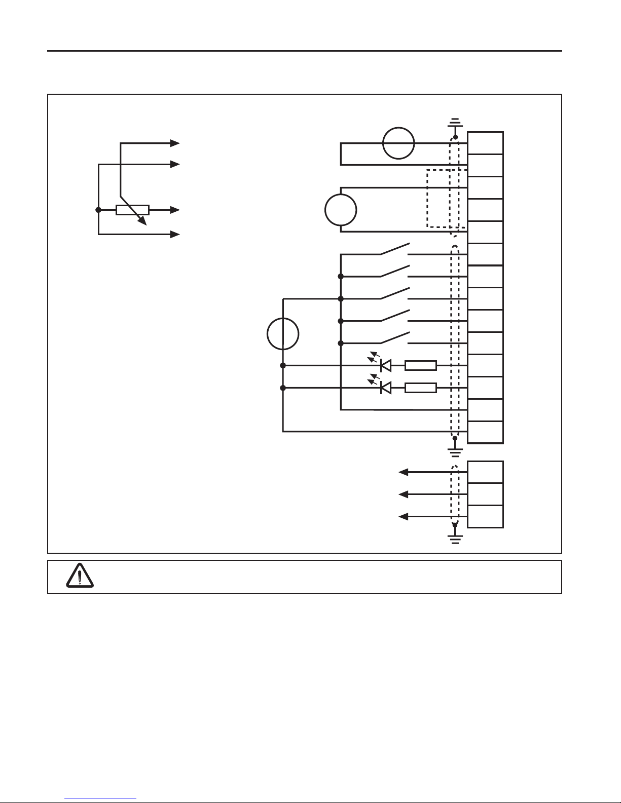
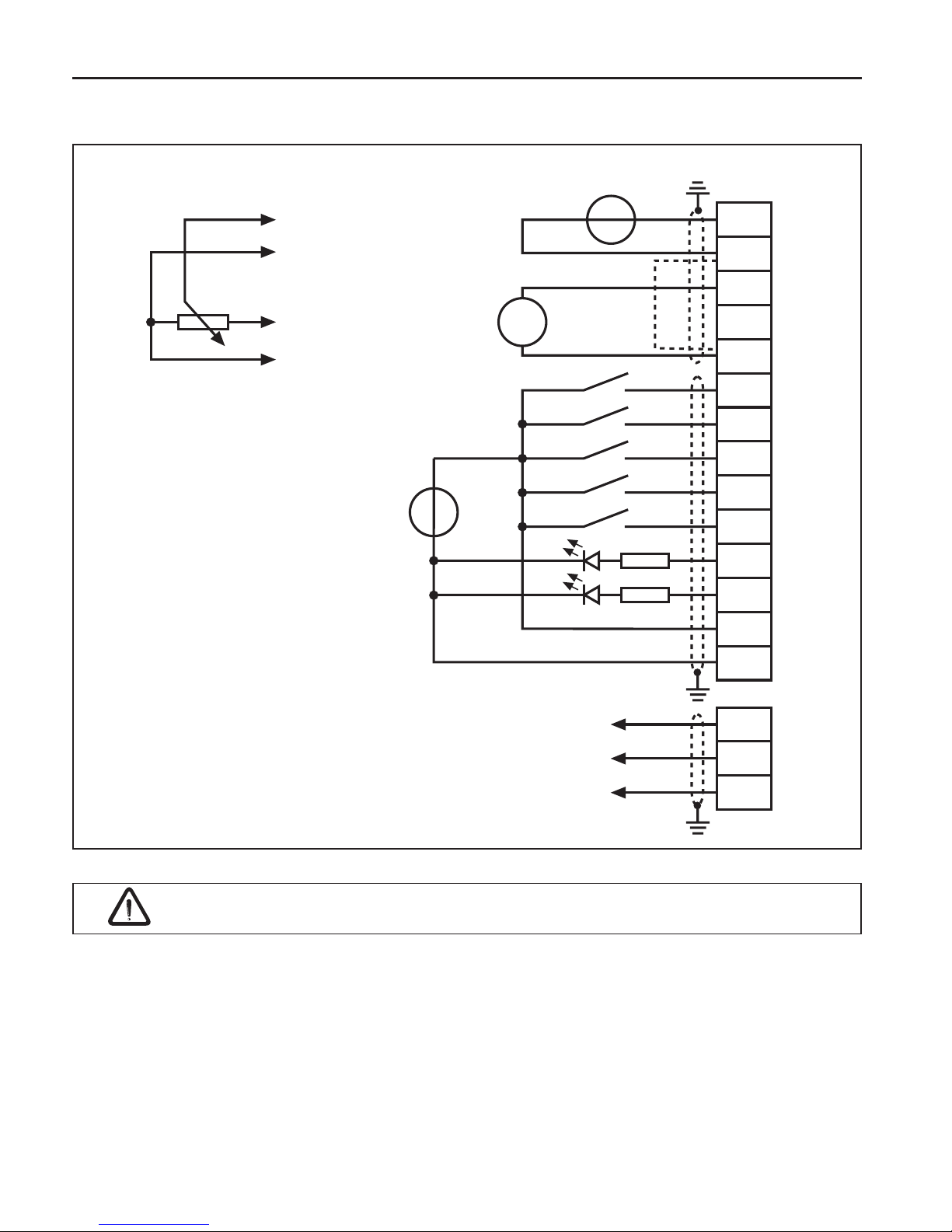
3.5.2 Anschluss der Steuerklemmleiste
Sollwertpotentiometer
3…10 kΩ
externe Spannungsversorgung
20…30 V DC ±0 %
1 A
Sollwertsignal
0…±10 V DC
Analogausgang
±10 V DC
max. 5 mA
1)
Potentialausgleichsleitung nur anschließen, wenn zwischen den Steuerungen ein
Potentialunterschied > 30 V besteht. Der Innenwiderstand reduziert sich hierbei auf 30 kΩ.
Bei induktiver Last am Relaisausgang ist eine Schutzbeschaltung vorzusehen (z.B.
Freilaufdiode) !
Die Steuerkarte muss immer mit einer externen Spannungsquelle versorgt werden. Dadurch
bleibt die Steuerung auch bei abgeschaltetem Leistungsteil in Betrieb. Um undenierte
Zustände bei externer Versorgung zu vermeiden, sollte grundsätzlich erst die Versorgung und dann
der Umrichter eingeschaltet werden.
Die Anschlüsse der Steuerklemmleiste sowie Gebereingänge weisen sichere Trennung gemäß
EN 50178 auf.
max. 30 V DC
0,01…1 A

D - 19
Bedienung des Gerätes
4. Bedienung des Gerätes
4.1 Zubehör zur Bedienung
4.1.1 Ohne Operator mit HSP5-Servicekabel
Für die Steuerung des KEB COMBIVERT ohne Operator ist ein spezielles HSP5-Kabel
(Artikelnummer 00.F5.0C0-0010) erforderlich. Es wird zwischen die HSP5-Schnittstelle
X4A und einer seriellen RS232-PC-Schnittstelle (COM1 oder COM2) angeschlossen. Die
Bedienung erfolgt über das Programm COMBIVIS.
Das HSP5-Servicekabel hat einen integrierten Pegelumsetzer. Der Anschluss eines
seriellen Standardkabels würde die PC-Schnittstelle zerstören.
4.1.2 Digitaloperator (Artikelnummer 00F5060-1000)
Als Zubehör zur lokalen Bedienung des KEB COMBIVERT F5 ist ein Operator erhältlich.
Um Fehlfunktionen zu vermeiden, muss der Umrichter vor dem Aufstecken / Abziehen
des Operators in den Status noP (Reglerfreigabe öffnen) gebracht werden. Bei der Inbetriebnahme des Umrichters wird immer mit den zuletzt abgespeicherten Werten bzw.
Werkseinstellung gestartet.
4.1.3 Interfaceoperator (Artikelnummer 00F5060-2000)
Der Interfaceoperator entspricht dem Funktionsumfang des Digitaloperators. Er ist jedoch
um eine serielle RS232/485-Schnittstelle erweitert.
Zur Verbindung des Interfaceoperators mit einem PC ist ein RS232-Kabel erforderlich. Die
Belegung ist auf der folgenden Seite dargestellt.
54321
9876
5-stelliges LED-Display
Betriebs-/Fehleranzeige
Normal „LED ein“
Fehler „LED blinkt“
Doppelfunktionstastatur
RS232/RS485
(nur 00F5060-2000)
Schnittstellenkontrolle
BUS-Betrieb „LED ein“
(nur 00.F5.060-2000)
START
FUNC.
SP E E D
ENTER
F/R
STOP
COMBIVERT
X6C X6D
X6B
HSP5
Diagnoseschnittstelle
(nur 00F5060-2000)
PIN RS485 Signal Bedeutung
1 - - reserviert
2 - TxD Sendesignal RS232
3 - RxD Empfangssignal RS232
4 A‘ RxD-A Empfangssignal A RS485
5 B‘ RxD-B Empfangssignal B RS485
6 - VP Versorgungsspannung +5 V (Imax=50 mA)
7 C/C‘ DGND Datenbezugspotential
8 A TxD-A Sendesignal A RS485
9 B TxD-B Sendesignal B RS485

D - 20
Bedienung des Gerätes
4.1.4 Fernbedienung
Zur Fernbedienung des KEB COMBIVERT F5 ist ein spezieller HSP5-Operator erhältlich.
Operator Kabel
Die letzten drei Ziffern der Artikelnummer bestimmen
die Länge des Kabels in dm.
00F5060-9000 00F50C0-2xxx
00F5060-9001 00F50C0-3xxx
4.1.5 Weitere Operatoren
Zusätlich zu den beschriebenen Operatoren kann der KEB COMBIVERT mit weiteren
Operatoren für spezielle Einsatzfälle (Probus, Interbus, Sercos, CAN) bestückt werden.
Weitere Informationen hierzu nden Sie auf unserer Homepage.
4.2 Tastaturbedienung
4.2.1 Parameternummern und /-werte
Beim Einschalten des KEB COMBIVERT F5 erscheint der Wert des Parameters CP.1.
Mit der Funktionstaste wird zwischen
Parameterwert und Parameternummer
gewechselt.
FUNC.
SPEED
Mit UP (▲) und DOWN (▼) wird die
Parameternummer oder bei veränderbaren
Parametern der Wert erhöht / verringert.
START
STOP
START
STOP
Grundsätzlich werden Parameterwerte beim Verändern sofort übernommen und nichtüchtig
gespeichert. Bei einigen Parametern ist es jedoch nicht sinnvoll, daß der eingstellte Wert
sofort übernommen wird. Bei diesen Parametern wird durch ENTER der eingestellte Wert
übernommen und nichtüchtig gespeichert. Wenn ein solcher Parameter verändert wird,
erscheint hinter der letzten Stelle ein Punkt.
Durch „ENTER“ wird der eingestellte Wert
übernommen und nichtüchtig gespeichert.
ENTER
F/R
2
3
5
2
3
7
RS 232-Kabel 3m
PC / Operator
Artikelnummer 00.58.025-001D
9 pol. SUB-D Stecker
F5-Operator
Gehäuse (PE)
9pol. SUB-D Kupplung
PC

D - 21
4.2.2 Rücksetzen von Fehlermeldungen
Tritt während des Betriebes eine Störung auf, wird die aktuelle Anzeige mit der Fehlermeldung
überschrieben. Durch ENTER wird die Fehlermeldung zurückgesetzt.
— Fehler —>
ENTER
F/R
Durch ENTER wird nur die Fehlermeldung in der Anzeige zurückgesetzt. Um den Fehler
selbst zurückzusetzen, muss erst die Ursache behoben werden und ein Reset oder ein
Kaltstart erfolgen.
4.2.3 Passworteingabe
Der KEB COMBIVERT ist mit einem umfassenden Passwortschutz ausgestattet. Abhängig
vom eingegebenen Passwort sind folgende Modis möglich:
Anzeige Modus
CP_ro Endkundenmenü (CP-Parameter) nur lesen
CP_on Endkundenmenü (CP-Parameter) lesen/schreiben
CP_SE Servicemenü (wie Endkundenmenü, jedoch mit den Ursprungsparametern)
APPL Applikationsmenü (alle Parametergruppen und Parameter sichtbar)
– Drivemodus (COMBIVERT kann über die Tastatur in Betrieb genommen
werden)
Das für die Anwendung zulässige Menü wird vom Maschinenbauer festgelegt. Die
Passworteingabe erfolgt generell über den Parameter CP.0. Das eingestellte Passwort/Menü
bleibt auch nach dem Ausschalten erhalten.
Beispiel: Änderung der CP-Parameter von nur lesen auf lesen/schreiben
Password
FUNC
ENTER
UP
Bedienung des Gerätes

D - 22
CP-Parameter
5.3 Parameterbeschreibung für F5-Servo
AnzeigeParameter Einstellbereich Auösung Default Einheit ENTER Ursprung
CP.00 Passworteingabe 0...9999 1 - - - ud.01
CP.01 Istdrehzahl Geber 1 ±4000 0,125 0 1/min - ru.09
CP.02 Sollwertanzeige ±4000 0,125 0 1/min - ru.01
CP.03 Umrichterstatus 0...255 1 0 - - ru.00
CP.04 Scheinstrom 0...6553,5 0,1 0 A - ru.15
CP.05 Scheinstrom / Spitzenwert 0...6553,5 0,1 0 A - ru.16
CP.06 Istmoment ±10000,00 0,01 0 Nm - ru.12
CP.07 Zwischenkreisspannung 0...1000 1 0 V - ru.18
CP.08
Zwischenkreisspannung / Spitzenwert
0...1000 1 0 V - ru.19
CP.09 Ausgangsspannung 0...778 1 0 V - ru.20
CP.10 Konguration Drehzahlregler 4...6 1 4 - - cS.00
CP.11 DSM Nennmoment 0,1...6553,5 0,1 LTK Nm - dr.27
CP.12 DSM Nenndrehzahl 0...32000 1 LTK 1/min - dr.24
CP.13 DSM Nennfrequenz 0,0...1600,0 0,1 LTK Hz - dr.25
CP.14 DSM Nennstrom 0,0...710,0 0,1 LTK A - dr.23
CP.15 DSM EMK Spannungskonstante 0...1000 1 LTK V - dr.26
CP.16 DSM Wicklungsinduktivität 0,01...500,00 0,01 LTK mH - dr.31
CP.17 DSM Wicklungswiderstand 0,000...50,000 0,001 LTK Ω - dr.30
CP.18 DSM Stillstandsdauerstrom 0,0...700,0 0,1 LTK A - dr.28
CP.19 Motoranpassung 0...3 1 1 - E Fr.10
CP.20 Systemlage 1 0...65535 1 57057 - - Ec.02
CP.21 Drehrichtungstausch Geber 1 0...19 1 0 - - Ec.06
CP.22 max. Sollwert Rechtslauf 0...4000 0,125 2100 1/min - oP.10
CP.23 Festwert 1 ±4000 0,125 100 1/min - oP.21
CP.24 Festwert 2 ±4000 0,125 -100 1/min - oP.22
CP.25 Beschleunigungszeit 0,00...300,00 0,01 5 s - oP.28
CP.26 Verzögerungszeit -0,01...300,00 0,01 5 s - oP.30
CP.27 S-Kurvenzeit 0,00...5,00 0,01 0 s - oP.32
CP.28 Quelle Momentensollwert 0...5 1 2 - E cS.15
CP.29 Absoluter Momentensollwert ±10000,00 0,01 LTK Nm - cS.19
CP.30 KP Drehzahl 0...32767 1 50 - - cS.06
CP.31 KI Drehzahl 0...32767 1 500 - - cS.09
CP.32 Schaltfrequenz 0...LTK 1 LTK - E uF.11
CP.33 Relaisausgang 1 / Funktion 0...78 1 4 - E do.2
CP.34 Relaisausgang 2 / Funktion 0...78 1 2 - E do.3
CP.35 Endschalterfehler / Reaktion 0...6 1 6 - - Pn.7
CP.36 Externer Fehler / Reaktion 0...6 1 0 - - Pn.3
CP.3 Umrichterstatus
Der Umrichterstatus zeigt den aktuellen Betriebszustand des Umrichters (z.B.
Vorwärtkonstantlauf, Stillstand usw.) an. Im Fehlerfall wird die aktuelle Fehlermeldung
angezeigt, auch wenn die Anzeige durch ENTER bereits zurückgesetzt wurde (FehlerLED im Operator blinkt noch). Statusmeldungen und Informationen über die Ursache und
Beseitigung, nden Sie unter „www.keb.de => Dokumentation => Bedienungsanleitungen
=> Sonstiges => Serviceinformationen => Fehler- und Statusmeldungen.doc“.

D - 23
CP-Parameter
CP.10 KongurationDrehzahlregelung
Dieser Parameter aktiviert die Drehzahl-, bzw. die Drehmomentregelung.
CP.10 Beschreibung
4 Drehzahlregelung
5 Drehmomentregelung
6 Drehzahl-/Drehmomentregelung
CP.19 Motoranpassung
Werksmäßig ist der Servo je nach Gerätegröße auf einen speziellen Motor angepasst.
Werden die Motordaten CP.11…CP.18 verändert, muss einmal CP.19 aktiviert werden.
Damit werden die Stromregler, die Momentengrenzkennlinie und die Momentenbegrenzung
neu eingestellt. Die Drehmomentgrenze wird dabei auf den Wert gesetzt, der im
Grunddrehzahlbereich maximal möglich ist (abhängig vom Umrichternennstrom). Maximal
3-faches Bemessungsmoment.
CP.19 Voreinstellung der motorabhängigen Regler Parameter.
1 Als Eingangsspg. wird die Spgs.klasse des Umrichters angenommen.
2
Als Eingangsspannung wird die beim Einschalten gemessene
Zwischenkreisspannung, dividiert durch √2, angenommen. So kann der
Frequenzumrichter an die tatsächlich vorhandene Netzspannung angepasst
werden (z.B. USA mit 460 V).
Bei aktiver Reglerfreigabe werden die Motorparameter nicht übernommen. In der Anzeige
erscheint „nco“!
CP.20 Systemlage 1
Mit diesem Parameter wird die Systemlage des angebauten Gebersystems eingestellt
(Werkseinstellung). Bei einem nicht ausgerichtetem Motor kann der Steller hiermit
angepasst werden. Wenn die Systemlage des Motors nicht bekannt ist, kann ein
automatischer Abgleich durchgeführt werden. Bevor mit dem Ableich angefangen wird,
muss die Drehrichtung überprüft werden. Die Drehzahlanzeige unter CP.1 muss bei
Rechtsdrehung des Motors von Hand positiv sein. Ist das nicht der Fall, kann mit CP.21,
wie beschrieben, die Drehrichtung getauscht werden. Wird die richtige Drehrichtung
angezeigt, kann mit dem Abgleich begonnen werden.
• Der angeschlossene Motor muss sich frei drehen können.
• Reglerfreigabe öffnen (Klemme X2A.16).
• CP.20 = 2206 eingeben.
• Reglerfreigabe schließen (Klemme X2A.16).
Der Motor wird jetzt mit seinem Nennstrom erregt und richtet sich in seine Nullage aus.
Ändert sich der Wert unter CP.20 nach ca. 5 s nicht mehr, ist der Abgleich abgeschlossen.
In diesem Fall, Reglerfreigabe öffnen.
Wird während des Abgleiches der Fehler E.EnC ausgelöst, ist die Drehrichtung falsch und
es muss mit CP.21 ein Drehrichtungswechsel vorgenommen werden. Der Lageabgleich
muss in diesem Fall wiederholt werden.
Werden Motoren mit ausgerichtetem Gebersystem verwendet, kann der durch das
automatiche Abgleichen ermittelte Wert auch direkt unter CP.20 eingegeben werden. Die
Abgleichwerte von bekannten Motoren der KEB COMBIVERT S4-Reihe, müssen mit der
Polpaarzahl des Motors multipliziert werden. Die unteren 16 Bit des Ergebnisses müssen
in CP.20 eingetragen werden.

D - 24
CP-Parameter
CP.21 Drehrichtungstausch Geber 1
Die Drehzahlanzeige unter CP.1 muss bei Rechtsdrehung des Motors von Hand positiv
sein. Wenn das Vorzeichen nicht stimmt, müssen bei Geräten mit Resolver SIN+ und SIN-
vertauscht werden. Dabei ist darauf zu achten, dass die Signale nicht mit dem inneren
Schirm kurzgeschlossen werden. Bei Geräten mit SIN/COS-Geber müssen die Signale
A(+) und A(-) getauscht werden. Ist dies zu aufwendig, kann mit diesem Parameter ein
Drehrichtungswechsel für den Gebereingang 1 durchgeführt werden.
CP.21 Bedeutung
0 kein Spurtausch
1 Spuren getauscht
2…3 reserviert für Initiatoreingang
CP.28 Quelle Momentensollwert
Mit CP.28 kann die erforderl. Sollwertquelle bei Drehmomentregelung eingestellt
werden.
CP.28 Bedeutung Einstellbereich
0 AN1+ / AN1- 0%…±100% = 0…±CP.29
1 AN2+ / AN2- 0%…±100% = 0…±CP.29
2 digital absolut 0…±CP.29
3…5 nur Applikationsmode
CP.33 Relaisausgang 1 / Funktion
CP.34 Relaisausgang 2 / Funktion
CP.33/34 bestimmen die Funktion der beiden Relaisausgänge (X2A.24-26, X2A.27-29).
Wert Funktion
0 Keine Funktion (generell aus)
1 Generell an
2 Run-Signal; auch bei DC-Bremse
3 Betriebsbereit-Signal (kein Fehler)
4 Störmelderelais
5 Störmelderelais (ohne Auto-Reset)
6 Warn- o. Fehlermeldung nach Schnellhalt
7 Überlast-Vorwarnung
8 Übertemperatur-Vorwarnung Endstufen
9 Ex. Übertemperatur-Vorwarnung Motor
11 Übertemperatur-Vorwarnung OHI
20 Istwert = Sollwert (CP.3 = Fcon, rcon, nicht bei noP, LS, Fehler, SSF)
21 Beschleunigen (CP.3 = FAcc, rAcc, LAS)
22 Verzögern (CP.3 = FdEc, rdEc, LdS)
23 Istdrehrichtung = Solldrehrichtung
24 Auslastung > Schaltpegel
1)
25 Wirkstrom > Schaltpegel
1)
27 Istwert (CP.1) > Schaltpegel
1)
28 Sollwert (CP.2) > Schaltpegel
1)
31 Abs. Sollwert an AN1 > Schaltlevel
1)
32 Abs. Sollwert an AN2 > Schaltlevel
1)
34 Sollwert an AN1 > Schaltpegel
1)
35 Sollwert an AN2 > Schaltpegel
1)
40 Hardware-Stromgrenze aktiv
41 Modulation An-Signal
47 Rampenausgangswert > Schaltpegel
1)

D - 25
CP-Parameter
Wert Funktion
48 Scheinstrom (CP.4) > Schaltpegel
1)
49 Rechtslauf (nicht bei nOP, LS, Schnellhalt oder Fehler)
50 Linkslauf (nicht bei nOP, LS, Schnellhalt oder Fehler)
51 Warnung E.OL2
52 Stromregler in der Begrenzung
53 Drehzahlregler in der Begrenzung
63 Betrag ANOUT1 > Schaltpegel
1)
64 Betrag ANOUT2 > Schaltpegel
1)
65 ANOUT1 > Schaltpegel
1)
66 ANOUT2 > Schaltpegel
1)
70 Treiberspg. aktiv (Sicherheitsrelais)
73 Betrag Wirkleistung > Schaltpegel
1)
74 Wirkleistung > Schaltpegel
1)
Nicht aufgeführte Werte sind nur für den Applikationsmodus
1)
Schaltpegel für CP.33 = 100; Schaltpegel für CP.34 = 4
CP.35 Endschalterfehler / Reaktion
Dieser Parameter bestimmt die Reaktion des Antriebes auf die Klemmen X2A.14 (F) bzw.
X2A.15 (R), welche als Endschalter programmiert sind. Die Reaktion des Antriebes erfolgt
entsprechend folgender Tabelle.
CP.35 Anzeige Reaktion Wiederanlauf
0 E.PRx sofortiges Abschalten der Modulation
Fehler beheben,
Reset
1 A.PRx
Schnellhalt / Abschalten der Modulation nach
Erreichen von Drehzahl 0
2 A.PRx Schnellhalt / Haltemoment bei Drehzahl 0
3 A.PRx sofortiges Abschalten der Modulation
Autoreset, wenn kein
Fehler mehr
4 A.PRx
Schnellhalt / Abschalten der Modulation nach
Erreichen von Drehzahl 0
5 A.PRx Schnellhalt / Haltemoment bei Drehzahl 0
6 ohne
keine Auswirkung auf den Antrieb, Störung wird
ignoriert !
entfällt
CP.36 Externer Fehler / Reaktion
Mit der externen Fehlerüberwachung können externe Geräte direkten Einuß auf den
Antrieb nehmen. Dieser Parameter bestimmt die Reaktion des Antriebes auf ein Signal
an Klemme X2A.12 (I3), entsprechend folgender Tabelle.
CP.36 Anzeige Reaktion Wiederanlauf
0 E.PRx sofortiges Abschalten der Modulation
Fehler beheben,
Reset
1 A.PRx
Schnellhalt / Abschalten der Modulation nach
Erreichen von Drehzahl 0
2 A.PRx Schnellhalt / Haltemoment bei Drehzahl 0
3 A.PRx sofortiges Abschalten der Modulation
Autoreset, wenn kein
Fehler mehr
4 A.PRx
Schnellhalt / Abschalten der Modulation nach
Erreichen von Drehzahl 0
5 A.PRx Schnellhalt / Haltemoment bei Drehzahl 0
6 ohne
keine Auswirkung auf den Antrieb, Störung wird
ignoriert !
entfällt

Anhang B
D - 26
B. Anhang B
B.1 CE-Kennzeichnung
CE gekennzeichnete Frequenzumrichter und Servoantriebe sind in Übereinstimmung mit
den Vorschriften der Niederspannungsrichtlinie 2006/95/EG entwickelt und hergestellt
worden.
Die Inbetriebnahme (d.h. die Aufnahme der bestimmungsgemäßen Verwendung) der Frequenzumrichter oder Servoantriebe ist solange untersagt, bis festgestellt wurde, dass die
Anlage oder Maschine den Bestimmungen der Maschinenrichtlinie 2006/42/EG sowie der
EMV-Richtlinie (2004/108/EG) entspricht (beachte EN 60204).
Die Frequenzumrichter und Servoantriebe erfüllen die Anforderungen der Niederspannungsrichtlinie 2006/95/EG. Die harmonisierten Normen der Reihe EN 61800-2 werden
angewendet.
Dies ist ein Produkt mit eingeschränkter Erhältlichkeit nach IEC 61800-3. Dieses Produkt
kann im Wohnbereich Funkstörungen verursachen; in diesem Fall kann es für den Betreiber
erforderlich sein, entsprechende Maßnahmen durchzuführen.
B.2 UL-Kennzeichnung
Eine Abnahme gemäß UL ist bei KEB Umrichtern auf dem Typenschild
durch nebenstehendes Logo gekennzeichnet.
Zur Konformität gemäß UL für einen Einsatz auf dem nordamerikanischen Markt sind
folgende Hinweise unbedingt zu beachten (englischer Originaltext):
•
240V units
Suitable For Use On A Circuit Capable Of Delivering Not More Than 10kA rms
Symmetrical Amperes, 240 Volts Maximum when Protected by Fuses or see Instruction
Manual for Alternate BCP.
480V units
Suitable For Use On A Circuit Capable Of Delivering Not More Than 10kA rms
Symmetrical Amperes, 480 Volts Maximum when Protected by Fuses or see Instruction
Manual for Alternate BCP.
•
Maximum Surrounding Air Temperature 45 °C (113 °F)
•
For control cabinet mounting as „Open Type“
•
Use In A Pollution Degree 2 Environment
•
Use 60/75°C Copper Conductors only
•
Motor protection by adjustment of current parameters.For adjustement see application
manual parameters Pn.14 and Pn.15
•
Not incorporated Overspeed Protection
•
Overload protection at 130 % of inverter output rated current (see type plate)
•
Integral solid state short circuit protection does not provide branch circuit protection.
Branch circuit protection must be provided in accordance with the Manufacturer Instructions, National Electrical Code and any additional local codes, or the equivalent.

D - 27
Anhang B
B.3 Weitere Anleitungen
Ergänzende Anleitungen und Hinweise zum Download nden Sie unter
www.keb.de > Dokumentation > Betriebsanleitungen
Allgemeine Anleitungen
• Teil 1 EMV- und Sicherheitshinweise
Gerätespezische Anleitungen
• Teil 2 Leistungsteile
• Teil 3 Steuerteil
Servicehinweise
• Download von Parameterlisten
• Fehlermeldungen
Anleitungen für Konstruktion und Entwicklung
• Applikationsanleitung
• Erstellung eines benutzerdenierten Parametermenü
• Programmierung der digitalen Eingänge
• Eingangssicherungen gemäß UL für COMBIVERT F5
Zulassungen und Approbationen
• CE-Konformitätserklärung
• UL-Yellow Card (http://www.ul.com)

D - 28
Notizen

GB - 3
GB

GB - 4
This manual describes the KEB COMBIVERT F5. Particular attention is paid to the installation,
the connection as well as the basic operation. Due to the various application and programming
possibilities, the application-specic connection and/or wiring diagram, the parameter adjustment
as well as instructions to the start-up are to be taken from the documentation of the machine
manufacturer.
A list of instruction manuals and documents giving assistance for the construction, documentation
and service is provided at the end of this manual. The safety and warning notes listed in this instruction manual as well as in other documentation must be observed at any rate to ensure a safe
operation. Non-observance of the safety instructions leads to the loss of any liability claims. The
safety and warning instructions specied in this manual do not lay claim on completeness. KEB
reserves the right to change/adapt specications and technical data without prior notice. The used
pictograms have following signicance:
Danger
Is used, if life or health of the user are endangered or substantial
damage to property can occur.
Warning
Caution
Attention
Is used, if a measure is necessary for safe and trouble-free operation.
observe at
all costs
Information
Is used, if a measure simplies the handling or operation of the
unit.
Aide
Tip
The information contained in the technical documentation, as well as any user-specic advice in
spoken and written and through tests, are made to best of our knowledge and information about
the application. However, they are considered for information only without responsibility. This also
applies to any violation of industrial property rights of a third-party.
Inspection of our units in view of their suitability for the intended use must be done generally by the
user. Inspections are particulary necessary, if changes are executed, which serve for the further
development or adaption of our products to the applications (hardware, software or download
lists). Inspections must be repeated completely, even if only parts of hardware, software or down-
load lists are modied. Original spare parts and authorized accessories by the manufacturer serve
as security. The use of other parts excludes liability for the damages which can result from it.
Application and use of our units in the target products is outside of our control and therefore exclusively in the area of responsibility of the user. Repairs may only be carried out by the manufacturer
or an authorised repair agency. Unauthorised opening and tampering may lead to bodily injury and
property damage and may entail the loss of warranty rights.

GB - 5
Table of Contents
1. Safety and Operating Instructions..... 6
2. Product description ............................ 7
2.1 Intended use.......................................... 7
2.2 Unit identication ................................... 7
2.3 Technical data ....................................... 8
2.4 Dimensions and Terminals .................. 10
3. Installation and Connection ..............11
3.1 Control cabinet installation ...................11
3.2 EMC-conform Installation .....................11
3.3 Connection of Power Circuit ................ 12
3.3.1 Wiring instructions ............................... 12
3.3.2 Terminal Strip X1A ............................... 12
3.3.3 Mains connection ................................ 13
3.3.4 Motor connection with terminal strip X1B
13
3.3.5 Connection of the temperature monito-
ring ...................................................... 14
3.3.6 Connection of a braking resistor with
temperature monitoring in accordance
with UL ................................................ 15
3.4 Encoder interface connection .............. 15
3.4.1 Resolver connection at KEB motors with
connector X3A ..................................... 15
3.4.2 Incremental encoder input / -emulation
X3B...................................................... 16
3.5 Control board Servo ............................ 17
3.5.1 Control terminal strip X2A.................... 17
3.5.2 Connection of the control terminal strip ...
18
4. Operation of the Unit ......................... 19
4.1 Operation Accessories ........................ 19
4.1.1 With HSP5 cable and without operator 19
4.1.2 Digital operator (part number 00F5060-
1000) ................................................... 19
4.1.3 Interface operator (part number
00F5060-2000) .................................... 19
4.1.4 Remote control ................................... 20
4.1.5 Other operators ................................... 20
4.2 Keyboard Operation ............................ 20
4.2.1 Parameter numbers and values .......... 20
4.2.2 Resetting error messages ................... 21
4.2.3 Password Input.................................... 21
5.3 Parameter description for F5 servo ..... 22
B. Annex B .............................................. 26
B.1 CE-Marking ......................................... 26
B.2 UL marking .......................................... 26
B.3 Additional Manuals .............................. 27

GB - 6
1. General
In operation, drive converters, depending on their degree of
protection, may have live, uninsulated, and possibly also moving
or rotating parts, as well as hot surfaces.
In case of inadmissible removal of the required covers, of improper
use, wrong installation or maloperation, there is the danger of
serious personal injury and damage to property.
For further information, see documentation.
All operations serving transport, installation and commissioning
as well as maintenance are to be carried out by skilled technical
personnel (Observe IEC 364 or CENELEC HD 384 or DIN VDE
0100 and IEC 664 or DIN/VDE 0110 and national accident
prevention rules!).
For the purposes of these basic safety instructions, „skilled
technical personnel“ means persons who are familiar with the
installation, mounting, commissioning and operation of the
product and have the qualications needed for the performance
of their functions.
2. Intended use
Drive converters are components designed for inclusion in electrical installations or machinery.
In case of installation in machinery, commissioning of the drive
converter (i.e. the starting of normal operation) is prohibited until
the machinery has been proved to conform to the provisions of
the directive 2006/42/EC (Machinery Directive). Account is to be
taken of EN 60204.
The drive converters meet the requirements of the Low-Voltage
directive 2006/95/EC. The harmonized standards of the series
EN 61800-5-1 for the drive converters were used.
The technical data as well as information concerning the supply
conditions shall be taken from the rating plate and from the documentation and shall be strictly observed.
3. Transport, storage
The instructions for transport, storage and proper use shall be
complied with.
The climatic conditions shall be in conformity with EN 618005-1.
4. Installation
The installation and cooling of the appliances shall be in accor-
dance with the specications in the pertinent documentation.
The drive converters shall be protected against excessive strains.
In particular, no components must be bent or isolating distances
altered in the course of transportation or handling. No contact shall
be made with electronic components and contacts.
Drive converters contain electrostatic sensitive components
which are liable to damage through improper use. Electric
components must not be mechanically damaged or destroyed
(potential health risks).
5. Electrical connection
When working on live drive converters, the applicable national
accident prevention rules (e.g. VBG 4) must be complied with.
The electrical installation shall be carried out in accordance
with the relevant requirements (e.g. cross-sectional areas of
conductors, fusing, PE connection). For further information, see
documentation.
Instructions for the installation in accordance with EMC require-
ments, like screening, earthing, location of lters and wiring, are
contained in the drive converter documentation. They must always
be complied with, also for drive converters bearing a CE marking.
Observance of the limit values required by EMC law is the responsibility of the manufacturer of the installation or machine.
6. Operation
Installations which include drive converters shall be equipped
with additional control and protective devices in accordance with
the relevant applicable safety requirements, e.g. act respecting
technical equipment, accident prevention rules etc.. Changes
to the drive converters by means of the operating software are
admissible.
After disconnection of the drive converter from the voltage supply,
live appliance parts and power terminals must not be touched
immediately because of possibly energized capacitors. In this
respect, the corresponding signs and markings on the drive
converter must be respected.
During operation, all covers and doors shall be kept closed.
7. Maintenance and servicing
The manufacturer’s documentation shall be followed.
KEEP SAFETY INSTRUCTIONS IN A SAFE PLACE!
Safety and Operating Instructions
for drive converters
(in conformity with the Low-Voltage Directive 2006/95/EC)
Important, absolutely read
1. Safety and Operating Instructions

GB - 7
Product description
2. Product description
2.1 Intended use
The digital servo controller KEB COMBIVERT F5-SERVO serves exclusively for the control
and regulation of synchronous servo motors. The operation of other electric consumers is
prohibited and can lead to the destruction of the unit.
On delivery the controllers are tuned to the servo motors supplied by KEB. Servo controllers
are components which are intended for the installation in electric systems or maschines.
2.2 Unit identication
A6 . F5 . S 3 A - 3 4 2 A
Motor cooling
0: Self-cooling 1: External cooling
A: as 0; varnished B: as 1; varnished
Encoder interface
2: Resolver
Motor speed
1: 1500 rpm 2: 2000 rpm
3: 3000 rpm 4: 4000 rpm
6: 6000 rpm
Input identication
2: 1/3-phase 230 V AC/DC
3: 3-phase 400 V AC/DC
Housing type A
Accessories
1: GTR7 3: GTR7 and lter
Control type
S: SERVO
Series F5
Motor design / Motor identication /-size
A0…GH: Standard systems
Others: customer- or special version

GB - 8
2.3 Technical data
Product description
1)
This value initiates the response of the hardware current limit. The maximum torque limit should be always below
this value, otherwise no more regulation is possible.
2)
The heat sink power loss is based on the losses of the power module and the rectier. There is no rectier power
loss at DC devices. The listed value must be dissipated via the mounting surface at at rear devices.
3)
At mains voltage >460 V multiply the nominal current with factor 0.86. Attention, with input rated voltage of 480 Vac
no braking resistor shall be connected.
4)
With sub-mounted lter in compliance with class C1 in accordance with EN 61800-3.
5)
Use E-MMC/ Type E - Manual Motor Controller according to UL508 / Class NKJH only. The following types are
accepted:
Manufacturer UL - File Type Required terminal line adaptor
Siemens E 156943
3RV1021-1xA10 3RV1928-1H
3RV1031-4xA10 –
ABB Stotz E 195536
MS325-xx S3-M3
MS450-xx –
Servo size 05 07 07 09
Housing size A A A A
Phases 1 3 1 3 3 3
Input rated voltage [V] 230 400
Output rated power [kVA] 0.9 1.6 1.8 2.8
Output rated current [A] 2.3 4 2.6 4.1
Stand still current [A] 2.5 4.4 2.9 4.5
Max. short time current
1)
[A] 4.6 8 5.2 8.2
OC-tripping current [A] 5.5 9.6 6.2 9.8
Input rated current [A] 4.6 3.2 8 5.6 3.6 6
Rated switching frequency [kHz] 8 8 8 4
Max. switching frequency [kHz] 8 8 8 8
Power loss at nominal operating [W] 38 35 55 50 65 65
Heat sink power losses
2)
[W] 28 25 45 40 55 55
Heat sink power losses (DC)
2)
[W] 25 22 40 35 52 50
Minimum braking resistor [Ω] 60 60 110 110
Typically braking resistor [Ω] 160 82 210 160
Maximal braking current [A] 7 7 7.5 7.5
Mains voltage U
N
3)
[V] 180…260 ±0 305…528 ±0
Mains frequency [Hz] 50…60 ±2
Output voltage [V] 3 x 0…U
N
Output frequency [Hz] 0…400
Max. motor line length (shielded)
4)
[m] 30
Max. motor line length (shielded) [m] 50
For use in USA
Max. mains fuse type RK5 [A] 10 6 15 10 6 10
Max. input fusing MMC type "E"
5)
[A] 10 6.3 16 10 10 10

GB - 9
Rockwell / Allen Bradley E 205542
140M-C2E-Bxx or Cxx –
140M-F8E-Cxx –
Moeller E 123500 PKZM0-xxE (only up to 25 A) BK25/3 - PKZ0-E
Where x or xx means that here current rating or letter for current rating is given.
Use only in mains Wye 480/277 V. Delta grounding is not permitted.
Site altitude maximal 2000 m above sea level. With site altitudes over 1000 m a derating
of 1 % per 100 m must be taken into consideration.
Overload function
0
50
100
150
200
250
300
s
100 120 140 160 180 200
%

GB - 10
Product description
2.4 Dimensions and Terminals
PE
L1
L2
L3
++
--
PE
L1
N/L2
L3
++
--
Wa
Ein Fe
schutz s
ist als allei
Schutzmaßna
nicht zulÌässig
Die Ko
entlad
beträg
T2
T1
PB
PA
WVU
PE
185
175
144
158
76
5
U, V, W Connection for servo motor
PA, PB Connection for braking resistor
T1, T2 Connection for temperature sensor / switch
L1, N/L2, L3 1/3-phase mains connection (230V-class)
L1, L2, L3 3-phase mains connection (400V-class)
++, -- DC voltage supply in-/output for DC-supply networks
250...370 V DC (230V class)
420...720 V DC (400V class)
PE Connection for shielding/earthing
Pay attention to the input voltage, since 230V and 400V class (3-phase) are possible!
Incremtental encoder
simulation X3B
Resolver X3A
X4A
X2A
X1B
230V class X1A
with operator
with Cover
400V class X1A
191 (with terminal strips)

GB - 11
Installation and Connection
3. Installation and Connection
3.1 Control cabinet installation
3.2 EMC-conform Installation
Installation position and min.
distances
150 mm
30 mm
100 mm
START
STOP
FUNC.
SPEED
ENTER
F/R
ANTRIEBSTECHNIK
START
STOP
FUNC.
SPEED
ENTER
F/R
ANTRIEBSTECHNIK
6 inch
1 inch
4 inch
Protective system (EN 60529): IP20
Operation temperature: -10…45 °C (14…113 °F)
Storage temperature: -25…70 °C (-13…158 °F)
max. heat sink temperature:
Size 05/230 V and 07-09/400 V 90 °C (194 °F)
Size 07/230 V 82 °C (180 °F)
Climatic category (EN 60721-3-3): 3K3
Environment (IEC 664-1): Pollution degree 2
Vibration/Jolt according to: German. Lloyd; EN50155
The at-rear design requires cooling measures by the
machine builder. This can be in the best case no further
measure at all (e.g. at cyclic operation with down times)
up to the dissipation of the entire, indicated heat loss at
rated operation.
Protect the COMBIVERT against aggressive
gases and aerosols !
• Always apply the shielding of motor and
control cables over a large contact surface on
both sides.
• Distance between control and power cables at
least 10…20 cm (4…8 inch).
• Lay motor and power cable separately.
• If it cannot be avoided, cross control and
power cables in a right angle.
• Install all cables as close as possible to the
mounting plate - ideal in a metal cable duct.
• Mount COMBIVERT well conducting with the
mounting plate. Remove the paint beforehand.
You can nd further instructions regarding the
EMC-conform wiring in the Internet at KEB.
GB - 12
7
L1
L2
L3
++
--
E
Installation and Connection
3.3 Connection of Power Circuit
3.3.1 Wiring instructions
• Core cross-section 1.5 mm²
• Strip 7 mm
• Optional use of wire-end ferrule
• After arresting the cable by removing the
screwdriver absolutely check for a rm t
Attach / remove terminal strip only at
tensionless state
3.3.2 Terminal Strip X1A
PE
L1
N/L2
L3
++
--
PE
L1
L2
L3
++
--
Terminal strip X1A / 230 V class
• 230 V AC / 1-phase (L1/N)
• 230 V AC / 3-phase (L1, L2, L3)
• DC-Supply 250…370 V DC (++, --)
Terminal strip X1A / 400 V class
• 400 V AC / 3-phase (L1, L2, L3)
• DC-Supply 420...720 V DC (++, --)
Absolutely observe the connecting voltage of the KEB COMBIVERT. A 230V-unit will
be immediately destructed on a 400V-power supply.
Never exchange the mains and motor cables.
Some countries demand that the PE-terminal is directly connected to the terminal
box (not over the mounting plate).

GB - 13
Installation and Connection
++
--
L1
PE
N/L2
L3
L1
PE
N
Mains connection 230 V 1-phase
++
--
L1
PE
N/L2
L3
L1
PE
L2
L3
++
--
L1
PE
L2
L3
L1
PE
L2
L3
++
--
L1
PE
N/L2
L3
+
-
++
--
L1
PE
L2
L3
+
-
1 x 230 V AC
3 x 1.5 mm²
Mains connection 230 V 3-phase
3 x 230 V AC
4 x 1.5 mm²
Mains connection 400 V 3-phase
3 x 400 V AC
4 x 1.5 mm²
DC-connection 230 V-class
250…370 V DC
2 x 1.5 mm²
DC-connection 400 V-class
2 x 1.5 mm²
420…720 V DC
3.3.3 Mains connection
3.3.4 Motor connection with terminal strip X1B
T2
T1
PB
PA
WVU
PE
• PE Connection for earthing
• U, V, W Servo motor
• PA, PB Braking resistor
• T1, T2 Temperature sensor / switch
Protection
• Fuse 10 A slow-blowing or power protective
switch
• RCD (residual current operated circuit-
breaker) type A or type B
• at DC-supply pay attention to the
permissible voltage range of the fuses

GB - 14
Installation and Connection
• Plug in all connectors only in off-circuit condition !
• Observe correct phase sequence of the motor !
• Shielded motor line
PTC
PTC
Brake +
Brake –
Motor
Power connector
A
B
C
D
1
2
3
4
PE
U
V
W
ext. brake supply unit
with own voltage supply
(optionally)
Apply shieldings over a large contact surface of
the mounting plate
gr/ye
1
2
3
7
8
5
6
Motor connector
3.3.5 Connection of the temperature monitoring
Motor-PTC
Other
• Terminals T1, T2
• Tripping resistance 1.65…4 kΩ
• Reset resistance 0.75…1.65 kΩ
• Design in accordance with VDE 0660 Part 302
• This function can be activated by the machine builder by software
• Do not lay connecting cable together with control cable
• Permissible in the motor cable only with double shielding
• Connect relay K1 for re prevention in regenerative operation (see 3.3.6)
Connector
PIN No.
Name
Cable
Core No.
1 U 1
4 V 2
3 W 3
2 green-yellow 4
A 5 5
B 6 6
C 7 7
D 8 8

GB - 15
1
2
3
4
5
6
7
8
9
10
11
12
3.4.1 Resolver connection at KEB motors with connector X3A
3.4 Encoder interface connection
18
The plugs may only be connected / disconnected when the inverter and supply voltage are
disconnected !
Motor
Resolver plug
Socket X3A
• Maximum line length 50 m
3.3.6 Connection of a braking resistor with temperature monitoring in accordance with UL
• PA, PB Connection for braking resistor
• Technical data (see chapter 2.3)
• During clearing of the temperature monitoring the input voltage is switched off
• for additional protection in regenerative operation connect the auxiliary contacts 11
and 12 of the line contactor K1 (see 3.3.5)
Braking resistors can develop very high surface temperatures, therefor install as safe-totouch as possible !
230 or 24 V AC/DC
drive
at 24 V AC/DC
check tripping
Housing
SIN - 1
SIN+ 10
REF- 5
REF+ 7
COS- 2
COS+ 11
Housing
5 SIN - red
4 SIN+ blue
6 REF- yellow
3 REF+ green
8 COS- pink
7 COS+ gray
With input rated voltage of
480 Vac no braking resistor shall
be connected.

GB - 16
18
3.4.2 Incremental encoder input / -emulation X3B
The encoder interface X3 is switchable from an incremental encoder emulation to an
incremental encoder input. The increments of the emulation are xed to 1024 for units with
resolver interface.
Max. input frequency: < 300 kHz
Signals: RS 422 / 2 track signals and zero signals
max. transmission link: 50 m
Approved encoder types: Kübler RS 422 signals with 10…30 V voltage supply
The 12 V supply voltage at X3B is loadable with
altogether 100 mA. If higher voltages / currents
are needed for the supply of the incremental
encoder, then the encoder must be supplied
with an external voltage.
Socket X3B
1
2
3
4
5
6
7
8
RJ45-Connector assignment
free 1
free 2
green 3
blue 4
red 5
yellow 6
gray 7
pink 8
free
free
REF+
SIN+
SIN REF-
COS+
COS-
PIN Signal
1 12 V
2 GND
3 A+
4 B+
5 B6 A7 N+
8 N-

GB - 17
Installation and Connection
3.5 Control board Servo
3.5.1 Control terminal strip X2A
1257810 11 12 13 24 25 2616 18 19 21 22
• Tightening torque 0,22…0,25 Nm (2 lb inches)
• Use shielded/drilled cables
• Lay shield on one side of the inverter onto earth
potential
• NPN control is not possible at the A servo !
X2A
PIN Function Name Description
1 + Set value input 1 AN1+
Difference voltage
0…±10 V DC ^ 0…±maximum speed, Ri = 55 kΩ
2 - Set value input 1 AN1-
5 Analog output
AN
OUT1
Programmable analog output 0…±10 V DC/ 5 mA.
Function is dened by the machine builder
7 +10V output CRF
Reference voltage output for set value potentiometer
(+10 V DC / max. 4 mA)
8 Analog Mass COM Mass for analog in- and outputs
10 Progr. input 1 I1 The function of the programmable inputs is dened by
the machine builder.
Switching voltage 13…30 V DC ±0 % smoothed
Ri=2,1 kΩ
11 Progr. input 2 I2
12 Progr. input 3 I3
13 Progr. input 4 I4
16
Voltage supply
Driver stage
ST
Supply of the driver stage
This input must be supplied with an external voltage of
20…30
V DC ±0 % / 0,2 A (UBR max. 3,6 Vss). When
switching off this voltage an error reset is executed.
18 Transistor output 1 O1 Programmable digital outputs
Load capacity maximal 50 mA for both outputs.
Function is dened by the machine builder
19 Transistor output 2 O2
21
Voltage supply
Control board
Uin
Supply of the control board
This input must be supplied with an external voltage of
20…30
V DC ±0 % / 0,8 A (UBR max. 3,6 Vss). Through
the separate supply the control can also be operated at
switched off driver/power section.
22 Digital Mass 0V Potential for digital in- / outputs
Relay 1
Programmable relay output (CP.33)
Load capacity max. 30 V DC / 0,01…1 A
Function is dened by the machine builder
24 NO contact RLA
25 NC contact RLB
26 Switching contact RLC
GB - 18
Installation and Connection
3.5.2 Connection of the control terminal strip
Set value potentiometer
3…10 kΩ
external voltage supply
20…30 V DC ±0 %
1 A
Set value signal
0…±10 V DC
analog output
±10 V DC
max. 5 mA
1)
Connect potential equalizing line only if a potential difference of > 30 V exists between
the controls. The internal resistance is reduced to 30 kΩ.
To avoid interferences a separate shielding must be provided for analog and digital control lines.
Depending on the use of the relay outputs, an extra shielding is to be used, too.
In case of inductive load on the relay outputs a protective wiring must be provided (e.g. freewheeling diode) !
The control board must always supply by an external voltage. This keeps the control in
operation even if the power stage is switched off. To prevent undened conditions at external
power supply the basic procedure is to rst switch on the power supply and after that the inverter.
The terminals of the control terminal strip and the transmitter inputs are securely isolated in
accordance with EN 50178.
max. 30 V DC
0.01…1 A

GB - 19
Operation of the Unit
4. Operation of the Unit
4.1 Operation Accessories
4.1.1 With HSP5 cable and without operator
A special cable (part number 00.F5.0C0-0001) is necessary for the control of the KEB
COMBIVERT without operator. It is connected between the HSP5-interface X4A and a
serial RS232-PC-interface (COM1 or COM2). The operation takes place via the PC-program
COMBIVIS.
The HSP5-cable has an integrated level converter. The connection of a serial
standard cable would destroy the PC-interface.
4.1.2 Digital operator (part number 00F5060-1000)
As an accessory for the local operation of the KEB COMBIVERT F5 an operator is available.
To prevent malfunctions, the inverter must be brought into nOP status before connecting /
disconnecting the operator (open control release). When starting the inverter, it is always
started with the last stored values or the factory setting.
4.1.3 Interface operator (part number 00F5060-2000)
The interface operator corresponds to the functional range of the digital operator. However,
it is enhanced by a serial RS232/485-interface.
A RS232-cable is needed to connect the interface operator with the PC. The assignment
is represented on the following page.
54321
9876
5-digit LED Display
Operating-/Error display
Normal "LED on"
Error "LED blinks"
Double function keyboard
RS232/RS485
(only 00F5060-2000)
Interface control
Transmit "LED on"
(only 00.F5.060-2000)
START
FUNC.
SP E E D
ENTER
F/R
STOP
COMBIVERT
X6C X6D
X6B
HSP5 diagnostic interface
(only 00F5060-2000)
PIN RS485 Signal Meaning
1 - - reserved
2 - TxD transmission signal RS232
3 - RxD receive signal RS232
4 A‘ RxD-A receive signal A RS485
5 B‘ RxD-B receive signal B RS485
6 - VP Voltage supply +5 V (Imax=50 mA)
7 C/C‘ DGND Data reference potential
8 A TxD-A transmission signal A RS485
9 B TxD-B transmission signal B RS485

GB - 20
Operation of the Unit
4.1.4 Remote control
For remote control of the KEB COMBIVERT F5 a special HSP5 operator is available.
Operator Cable
The last three digits of the part number indicate the
length of the cable in dm.
00F5060-9000 00F50C0-2xxx
00F5060-9001 00F50C0-3xxx
4.1.5 Other operators
In addition to the described operators the KEB COMBIVERT can be equipped with further
operators for special applications (Probus, Interbus, Sercos, CAN, DeviceNet). You nd
further information on that on our home page.
4.2 Keyboard Operation
4.2.1 Parameter numbers and values
When switching on KEB COMBIVERT F5 the value of parameter CP.1 appears.
The function key changes between the parameter
value and parameter number.
FUNC.
SPEED
With UP (▲) and DOWN (▼) the value of the
parameter number is increased/decreased with
changeable parameters.
START
STOP
START
STOP
Principally during a change, parameter values are immediately accepted and stored nonvolatile. However, with some parameters it is not useful that the adjusted value is accepted
immediately. In these cases the adjusted value is accepted and stored non-volatile by
pressing ENTER. When this type of parameter is changed a point appears behind the
last digit.
By pressing „ENTER“ the adjusted value is
accepted and non-volatile stored.
ENTER
F/R
2
3
5
2
3
7
RS232-cable 3m
PC / Operator
Part number 00.58.025-001D
9-pole SUB-D connector
F5-Operator
Housing (PE)
9 pole SUB-D female
PC

GB - 21
4.2.2 Resetting error messages
If a malfunction occurs during operation, then the actual display is overwritten by the alarm
message. The alarm message in the display is reset by ENTER.
— Error —>
ENTER
F/R
With ENTER only the error message in the display is reset. In order to reset the error itself,
the cause must be removed or a power-on reset must be made.
4.2.3 Password Input
The KEB COMBIVERT is outtted with a comprehensive password protection. In dependence
on the entered password the following modes are possible:
Display Mode
CP_ro End customer menu (CP-Parameter) read-only
CP_on End customer menu (CP-Parameter) read/write
CP_SE Service menu (like end customer menu, but with the original parameters )
APPL Application menu (all parameter groups and parameters are visible)
– Drive mode (COMBIVERT can be put into operation by the keyboard )
The menu admissible for the application is dened by the machine builder. The password
input is generally made over the parameter CP.0. The adjusted password/menu is maintained
even after switching off.
Example: Changing the CP-parameter from read-only to read/write
Password
FUNC
ENTER
UP
Operation of the Unit

GB - 22
CP-Parameter
5.3 Parameter description for F5 servo
Display Parameter Setting Range Resolution Default Unit ENTER Based on
CP.00 Password input 0...9999 1 - - - ud.01
CP.01 Encoder 1 speed ±4000 0.125 0 rpm - ru.09
CP.02 Setpoint display ±4000 0.125 0 rpm - ru.01
CP.03 Inverter state 0...255 1 0 - - ru.00
CP.04 Apparent current 0...6553.5 0.1 0 A - ru.15
CP.05 Apparent current / peak value 0...6553.5 0.1 0 A - ru.16
CP.06 Actual torque display ±10000.00 0.01 0 Nm - ru.12
CP.07 DC-link voltage 0...1000 1 0 V - ru.18
CP.08 DC-link voltage / peak value 0...1000 1 0 V - ru.19
CP.09 Output voltage 0...778 1 0 V - ru.20
CP.10 Speed control conguration 4...6 1 4 - - cs.00
CP.11 DSM rated torque 0.1...6553.5 0.1 LTK Nm - dr.27
CP.12 DSM rated speed 0...32000 1 LTK rpm - dr.24
CP.13 DSM rated frequency 0.0...1600.0 0.1 LTK Hz - dr.25
CP.14 DSM rated current 0.0...710.0 0.1 LTK A - dr.23
CP.15 DSM EMK voltage constant 0...1000 1 LTK V - dr.26
CP.16 DSM winding inductance 0.01...500.00 0.01 LTK mH - dr.31
CP.17 DSM winding resistance 0.000...50.000 0.001 LTK Ω - dr.30
CP.18 DSM current for zero speed 0.0...700.0 0.1 LTK A - dr.28
CP.19 Load motor dependent parameter 0...3 1 1 - E fr.10
CP.20 Absolute position enc.1 0...65535 1 57057 - - ec.02
CP.21 Encoder 1 rotation 0...19 1 0 - - ec.06
CP.22 max. reference forward 0...4000 0.125 2100 rpm - op.10
CP.23 Step value 1 ±4000 0.125 100 rpm - op.21
CP.24 Step value 2 ±4000 0.125 -100 rpm - op.22
CP.25 Acceleration time 0.00...300.00 0.01 5 s - op.28
CP.26 Deceleration time -0.01...300.00 0.01 5 s - op.30
CP.27 S-curve time 0.00...5.00 0.01 0 s - op.32
CP.28 Torque reference source 0...5 1 2 - E cs.15
CP.29 Abs. torque reference ±10000.00 0.01 LTK Nm - cs.19
CP.30 KP speed 0...32767 1 50 - - cs.06
CP.31 KI speed 0...32767 1 500 - - cs.09
CP.32 Switching frequency 0...LTK 1 LTK - E uf.11
CP.33 Relay output 1 / function 0...78 1 4 - E do.2
CP.34 Relay output 2 / function 0...78 1 2 - E do.3
CP.35 Limit switch / stopping mode 0...6 1 6 - - pn.7
CP.36 External Fault / stopping mode 0...6 1 0 - - pn.3
CP.3 Inverter state
In parameter „inverter status“ the actual operating condition of the frequency inverter
is displayed. In the case of an error the current error message is displayed, even if the
display has already been reset with ENTER (error-LED on the operator is still blinking).
Status messages and information about the cause and removal are to be found in www.
keb.de => Documentation => Operating Instructions => Other => Service informations =>
Error and status messages.doc.

GB - 23
CP-Parameter
CP.10 Speedcontrolconguration
This parameter activates the speed or the torque control.
CP.10 Description
4 Speed control
5 Torque control
6 Speed / torque control
CP.19 Load motor dependent parameter
The factory settings of the servo correspond to the size of the unit and the respective
motor. If the motor data in CP.11…18 are changed, then CP.19 must be activated once.
This re-adjusts the current controller, torque curve and torque limit. The torque limit is set
at the value, that is maximally possible in the basic speed range (depending on inverter
rated current). Rated motor torque x 3 at maximum.
CP.19 Pre-adjustment of the motor-dependent control-parameters.
1 The voltage class of the inverter is taken as input voltage.
2
The measured DC-link voltage / √2 measured at switch on is taken as input
voltage. Thus the frequency inverter can be adapted to the actually available
mains voltage (e.g. USA with 460 V).
When control release is active the adjustment was not completed. „nco“ appears in the
display!
CP.20 Absolute position enc. 1
The system position of the attached resolver system is adjusted at EC.07. With this
parameter it is possible to adjust the controller to a not aligned motor. If the ystem position
of the motor is unknown an automatic trimming can be done. Before starting with the
adjustment, the direction of rotation must be checked. The speed display at CP.1 must be
positive when the engine runs manual in clockwise direction. If that is not the case, the
direction of rotation can be exchanged as described with CP.21. If the correct direction of
rotation is displayed, it can be started with the adjustment.
• The connected motor must be able to rotate freely.
• Open control release (terminal X2A.16).
• Set CP.20 = 2206.
• Close control release (terminal X2A.16).
Now the motor is excited with its rated current and aligned to its zero position. The
adjustment is nished when the displayed system position at CP.20 does not change for
approx. 5 s. In this case open control release and switch off the unit.
If the error message E.EnC is displayed during trimming the direction of rotation must be
checked (CP.21). In this case the position trimming must be repeated.
In case that motors with aligned encoder system are used, the value which has been
established by the automatic trimming, can be entered under CP.20 as well. The adjustment
values of known motors of the KEB COMBIVERT S4 series must be multiplied by the polepair number of the motor. The lower 16 bits of the result must be entered in CP.20.
CP.21 Encoder 1 rpotation
The speed display at CP.1 must be positive when the engine runs manual in clockwise
direction. The signals SIN+ and SIN- of the resolver have to be changed, if the sign is
wrong. Please ensure that the signals are not short-circuited with the internal shield.

GB - 24
CP-Parameter
The signals A(+) and A(-) must be changed for units with SIN/COS encoder. Should this
involve too much effort then you can achieve a rotation reversal of encoder 1 by means
of this parameter.
CP.21 Meaning
0 Tracks not exchanged
1 Track exchanged
2…3 Reserved for initiator input
CP.28 Torque reference source
With CP.28 the required setpoint source for torque control can be adjusted.
CP.28 Meaning Setting Range
0 AN1+ / AN1- 0%…±100% = 0…±CP.29
1 AN2+ / AN2- 0%…±100% = 0…±CP.29
2 Digital absolute 0…±CP.29
3…5 Only application mode
CP.33 Relay output 1 / function
CP.34 Relay output 2 / function
CP.33/34 determine the function of the two relay outputs (X2A.24-26, X2A.27-29).
Value Function
0 No function (generally off)
1 Generally on
2 Run signal; also by DC-braking
3 Ready signal (no error)
4 Fault relay
5 Fault relay (without auto-reset)
6 Warning or error message after abnormal stopping
7 Overload pre-warning
8 Overtemperature alert signal power stage
9 Ex. overtemperature pre-warning motor
11 Overtemperature pre-warning OHI
20 Actual value = set value (CP.3 = Fcon, rcon, not at noP, LS, error, SSF)
21 Accelerate (CP.3=FAcc, rAcc, LAS)
22 Decelerate (CP.3 = FdEc, rdEc, LdS)
23 Real direction of rotation = set direction of rotation
24 Utilization > switching level
1)
25 Active current > switching level
1)
27 Real value (CP.1) > switching level
1)
28 Setpoint (CP.2) > switching level
1)
31 Absolute setpoint on AN1 > switching level
1)
32 Absolute setpoint on AN2 > switching level
1)
34 Setpoint at AN1 > switching level
1)
35 Setpoint at AN2 > switching level
1)
40 Hardware current limit activated
41 Modulation on-signal
47 Ramp output value>switching level
1)
48 Apparent current (CP.4) > switching level
1)
49 Forward running (not at nOP, LS, abnormal stopping or error)
50 Reverse running (not at nOP, LS, abnormal stopping or error)
51 Warning E.OL2
52 Current regulator limit reached
53 Speed regulator limit reached

GB - 25
CP-Parameter
Value Function
63 Absolut value ANOUT1 > switching level
1)
64 Absolut value ANOUT2 > switching level
1)
65 ANOUT1 > switching level
1)
66 ANOUT2 > switching level
1)
70 Driver voltage activ (safety relay)
73 Absolut active power > switching level
1)
74 Active power > switching level
1)
Unlisted values are only for application mode
1)
Switching level of CP.33 = 100; switching level of CP.34 = 4
CP.35 Limit switch / stopping mode
This parameter determines the reaction of the drive to terminal X2A.14 (F) and/or X2A.15
(R), which are programmed as limit switches. The reaction of the drive is shown in the
table below.
CP.35 Display Response Restart
0 E.PRx Immediate disabling of modulation
Remove fault,
reset
1 A.PRx
Quick stopping / disabling of modulation after
reaching speed 0
2 A.PRx Quick stop / holding torque at speed 0
3 A.PRx Immediate disabling of modulation
Autoreset, if no fault
is present
4 A.PRx
Quick stopping / disabling of modulation after
reaching speed 0
5 A.PRx Quick stop / holding torque at speed 0
6 None No effect to the drive, fault is ignored ! Inapplicable
CP.36 External Fault / stopping mode
With the external error monitoring external units can take direct inuence on the drive.
This parameter determines the response of the drive to a signal at terminal X2A.12 (I3)
according to following table.
CP.36 Display Response Restart
0 E.PRx Immediate disabling of modulation
Remove fault,
reset
1 A.PRx
Quick stopping / disabling of modulation after
reaching speed 0
2 A.PRx Quick stop / holding torque at speed 0
3 A.PRx Immediate disabling of modulation
Autoreset, if no fault
is present
4 A.PRx
Quick stopping / disabling of modulation after
reaching speed 0
5 A.PRx Quick stop / holding torque at speed 0
6 None No effect to the drive, fault is ignored ! Inapplicable

Annex B
GB - 26
B. Annex B
B.1 CE-Marking
CE marked frequency inverter and servo drives were developed and manufactured to comply
with the regulations of the Low-Voltage Directive 2006/95/EC.
The inverter or servo drive must not be started until it is determined that the installation
complies with the Machine directive (2006/42/EG) as well as the EMC-directive (2004/108/
EC)(note EN 60204).
The frequency inverters and servo drives meet the requirements of the Low-Voltage Directive
2006/95/EC. The harmonized standards of the series EN 61800-2 were used.
This is a product of limited availability in accordance with IEC 61800-3. This product may
cause radio interference in residential areas. In this case the operator may need to take
corresponding measures.
B.2 UL marking
Acceptance according to UL is marked at KEB inverters with the adjacent
logo on the type plate.
To be conform according to UL for use on the North American Market the following
instructions must be observed (original text of the UL-File):
•
240V units
Suitable For Use On A Circuit Capable Of Delivering Not More Than 10kA rms
Symmetrical Amperes, 240 Volts Maximum when Protected by Fuses or see Instruction
Manual for Alternate BCP.
480V units
Suitable For Use On A Circuit Capable Of Delivering Not More Than 10kA rms
Symmetrical Amperes, 480 Volts Maximum when Protected by Fuses or see Instruction
Manual for Alternate BCP.
•
Maximum Surrounding Air Temperature 45 °C (113 °F)
•
For control cabinet mounting as „Open Type“
•
Use in a pollution degree 2 environment
•
Use 60/75°C Copper Conductors Only
•
Motor protection by adjustment of current parameters.For adjustement see application
manual parameters Pn.14 and Pn.15.
•
Not incorporated Overspeed Protection
•
Overload protection at 130 % of inverter output rated current (see type plate)
•
Integral solid state short circuit protection does not provide branch circuit protection.
Branch circuit protection must be provided in accordance with the Manufacturer Instructions, National Electrical Code and any additional local codes, or the equivalent.

GB - 27
Annex B
B.3 Additional Manuals
You nd supplementary manuals and instructions for the download under
www.keb.de > Documentation >Operation instruction
General instructions
• Part 1 EMC-and safety instructions
Unit-specic instructions
• Part 2 Power Circuit
• Part 3 Control Circuit
Service notes
• Up- /Download of parameter lists with KEB COMBIVERT
• Error messages
Instruction and information for construction and development
• Application Manual
• Preparation of a user-dened parameter menu
• Programming of the digital inputs
• UL input fusing for COMBIVERT F5
Approvals and approbations
• Declaration of conformity CE
• UL-Yellow Card (http://www.ul.com)

Notizen / Notes
28

Notizen / Notes
29

KEB Antriebstechnik Austria GmbH
Ritzstraße 8 • A-4614 Marchtrenk
fon: +43 7243 53586-0 • fax: +43 7243 53586-21
net: www.keb.at • mail: info@keb.at
KEB Antriebstechnik
Herenveld 2 • B-9500 Geraadsbergen
fon: +32 5443 7860 • fax: +32 5443 7898
mail: vb.belgien@keb.de
KEB Power Transmission Technology (Shanghai) Co.,Ltd.
No. 435 QianPu Road, Songjiang East Industrial Zone,
CHN-201611 Shanghai, P.R. China
fon: +86 21 37746688 • fax: +86 21 37746600
net: www.keb.cn • mail: info@keb.cn
KEB Antriebstechnik Austria GmbH
Organizační složka
K. Weise 1675/5 • CZ-370 04 České Budějovice
fon: +420 387 699 111 • fax: +420 387 699 119
net: www.keb.cz • mail: info.keb@seznam.cz
KEB Antriebstechnik GmbH
Wildbacher Str. 5 • D–08289 Schneeberg
fon: +49 3772 67-0 • fax: +49 3772 67-281
mail: info@keb-combidrive.de
KEB España
C/ Mitjer, Nave 8 - Pol. Ind. LA MASIA
E-08798 Sant Cugat Sesgarrigues (Barcelona)
fon: +34 93 897 0268 • fax: +34 93 899 2035
mail: vb.espana@keb.de
Société Française KEB
Z.I. de la Croix St. Nicolas • 14, rue Gustave Eiffel
F-94510 LA QUEUE EN BRIE
fon: +33 1 49620101 • fax: +33 1 45767495
net: www.keb.fr • mail: info@keb.fr
KEB (UK) Ltd.
6 Chieftain Buisiness Park, Morris Close
Park Farm, Wellingborough GB-Northants, NN8 6 XF
fon: +44 1933 402220 • fax: +44 1933 400724
net: www.keb-uk.co.uk • mail: info@keb-uk.co.uk
KEB Italia S.r.l.
Via Newton, 2 • I-20019 Settimo Milanese (Milano)
fon: +39 02 33535311 • fax: +39 02 33500790
net: www.keb.it • mail: kebitalia@keb.it
KEB Japan Ltd.
15–16, 2–Chome, Takanawa Minato-ku
J–Tokyo 108-0074
fon: +81 33 445-8515 • fax: +81 33 445-8215
mail: info@keb.jp
KEB Korea Seoul
Room 1709, 415 Missy 2000
725 Su Seo Dong, Gang Nam Gu
ROK-135-757 Seoul/South Korea
fon: +82 2 6253 6771 • fax: +82 2 6253 6770
mail: vb.korea@keb.de
KEB RUS Ltd.
Lesnaya Str. House 30, Dzerzhinsky (MO)
RUS-140091 Moscow region
fon: +7 495 550 8367 • fax: +7 495 632 0217
net: www.keb.ru • mail: info@keb.ru
KEB Sverige
Box 265 (Bergavägen 19)
S-43093 Hälsö
fon: +46 31 961520 • fax: +46 31 961124
mail: vb.schweden@keb.de
KEB America, Inc.
5100 Valley Industrial Blvd. South
USA-Shakopee, MN 55379
fon: +1 952 224-1400 • fax: +1 952 224-1499
net: www.kebamerica.com • mail: info@kebamerica.com
© KEB
Mat.No. 00F5S1M-KA03
Rev. 1G
Date 10/2010
More and newest addresses at http://www.keb.de
Karl E. Brinkmann GmbH
Försterweg 36-38 • D-32683 Barntrup
fon: +49 5263 401-0 • fax: +49 5263 401-116
net: www.keb.de • mail: info@keb.de
KEB worldwide…
 Loading...