

Page 1
BETRIEBSANLEITUNG
00.U0.HE0-K310
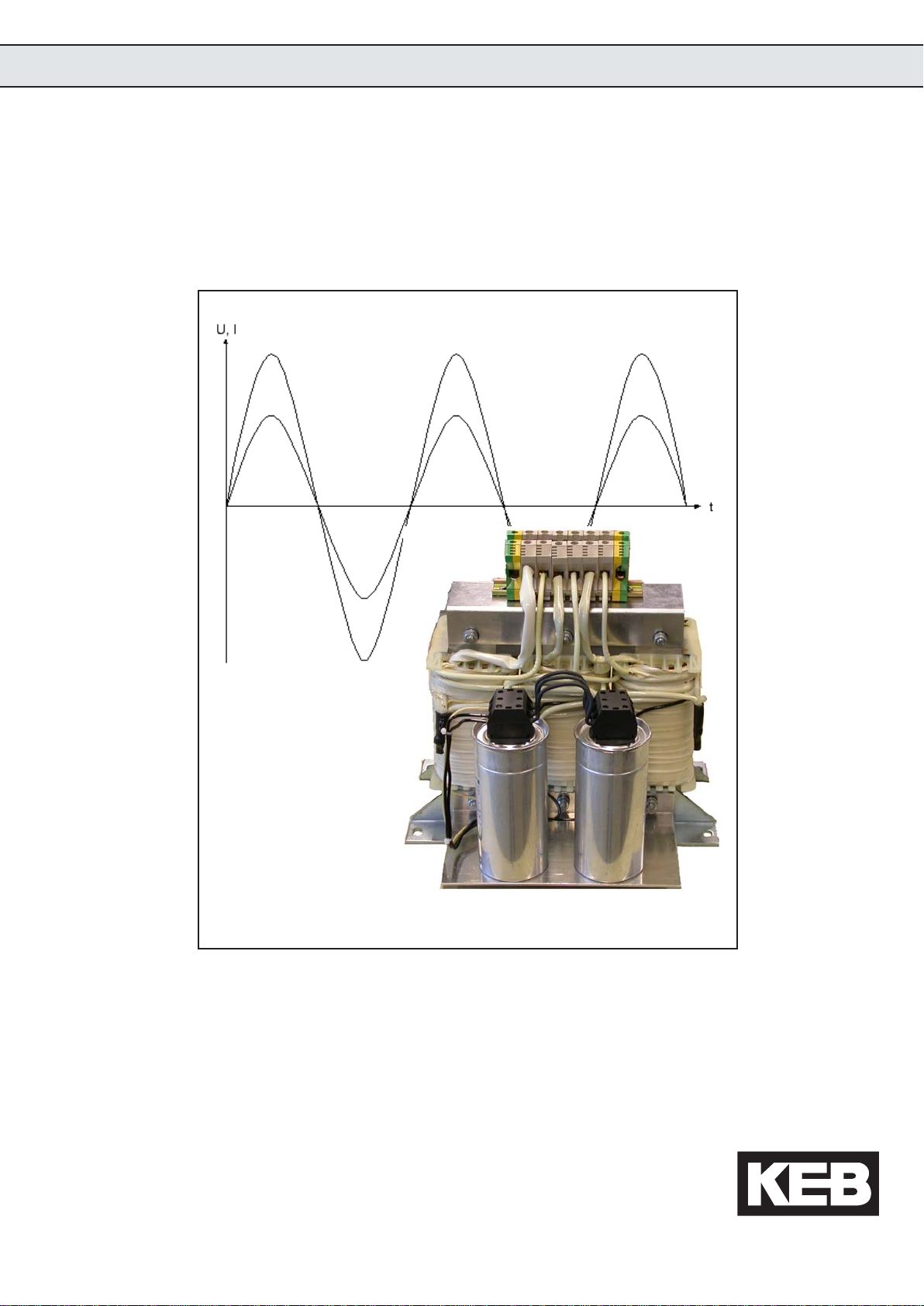
KEB COMBILINE Harmonic Filter
11/2005
Page 2

2
Page 3

1. Safety Instructions ............................................................................. 5
2. Product Description ........................................................................... 7
2.1 Technical Data of the 400V Class...................................................................7
2.2 Ambient Conditions ......................................................................................... 7
2.3 Input Rated Current ........................................................................................ 7
2.4 Dimensions ..................................................................................................... 8
2.5 Description ......................................................................................................9
3. Installation ........................................................................................ 11
3.1 Connection .................................................................................................... 11
3.2 Installation Instructions ................................................................................. 11
4. Oscillograms..................................................................................... 12
5. Annex................................................................................................ 14
5.1 Fourier Analysis/ Spectrum ........................................................................... 14
5.2 Formula ......................................................................................................... 14
GB - 3
Page 4

GB - 4
Page 5
1. Safety Instructions
Only qualified
electro-
personnel
The directions in this chapter must be absolutely observed for the following
reasons:
• Safety for people and machines
• Function and susceptibility to faults
• Technical inspectorate acceptance and certification
• Guarantee and warranties
General
The KEB harmonic filter is used for reduction of the line harmonics. The filter is a
continuity filter like a laminated mains choke.
the line during optimal conditions are created for the inverter on the output side
of the filter. Fundamentally the filter module is reliable on delivery.
All work from the transport, to installation and start-up as well as maintenance
may only be done by qualified personnel (IEC 364 and/or CENELEC HD 384
and IEC-Report 664 and note national safety regulations). According to this
manual qualified staff means those who are able to recognise and judge the
possible dangers based on their technical training and experience and those
with knowledge of the relevant standards and who are familiar with the field of
power transmission (VDE 0100, VDE 0160 (EN 50178), VDE 0113 (EN 60204)
as well as the appropriate regulations for your area).
A
sinusoidal current is supplied to
Observe
Standards
Harmonic filters must be designed that they fulfill their function when the installation
is correct and with specified application in error-free operation and cause no
danger for persons. This applies also to the co-operation with the entire system.
Use as directed
The harmonic filter must not be started until it is determined that the installation
complies with 89/392/EEC (machine directive) as well as the EMC-directive
(89/336/EEC)(note EN60204).
Changes of the harmonic filter are not allowed. The guarantee expires if the
product is changed or disassembled or operated in contradiction to our
instructions.
Operation of the harmonic filter is exclusively permissible at VDE-conform
networks of public electrical power companies! Not observance can lead to
reduction of the filter effect and to destruction of the filter module.
In accordance with the corresponding standards and guidelines operation is not
allowed also at short-time overcompensated networks and/or reactive-power
compensation equipment without chokes. For this the occuring overvoltages
can damage all connected consumers through oscillation procedures.
GB - 5
Page 6

Electrical Connection
Before any installation and connection work, the system must be switched off
and secured.
Protect against
accidental
contact
Instructions for EMC conform installation
The connection line between frequency inverter and filter module must be as
short as possible and close to reference potential.
Personal protection
Dangerous voltage can be available at the mains connections after switching off
the network.
GB - 6
Page 7
2. Unit Description
5
2.1 Technical Data of the 400V Class
Volt age c l as s 400V
Rated volt age 400V
Permiss ibl e range 360V to 440V
Mains frequency 50Hz/ 60Hz **
Overload c apac it y 150% for 60 sec.
All 10 mi n.
EN 6014 6-1-1/
Rating c lass III
Efficiency @ * > 99%***
THDI @ * <= 8%
cos phi * aprox. 0, 99
* = Rated operation
** = At rated voltage > = 460V multiply the rated current with factor 0,86
*** = Upto connection power >= 30kW motor rating power power at frequency inverter
2.2 Ambient Conditions
Storage temperature -25...70 °C (-13...158 °F)
Operating temperature -10...45 °C (14...113 °F)
Model / protec tive sys tem (EN 60
Environm ent (IEC 664-1) Poll ut ion degree 2
Climat i c c a t e gori e (EN 60721-3 -3) 3K3
IP20
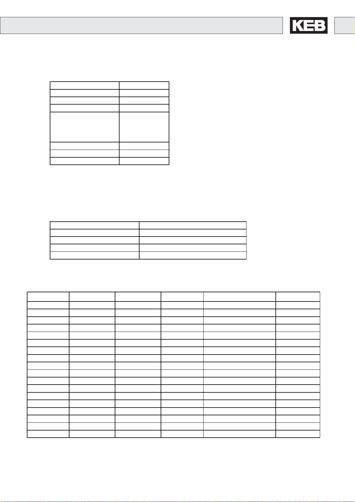
2.3 Input Rated Current
Part No. Irating [A] Prating [kW]
12.Z1.C04-1000
13.Z1.C04-1000
14.Z1.C04-1000
15.Z1.C04-1000
16.Z1.C04-1000
17.Z1.C04-1000
18.Z1.C04-1000
19.Z1.C04-1000
20.Z1.C04-1000
21.Z1.C04-1000
22.Z1.C04-1000
23.Z1.C04-1000
24.Z1.C04-1000
25.Z1.C04-1000
26.Z1.C04-1000
27.Z1.C04-1000
28.Z1.C04-1000
29.Z1.C04-1000
10
12,6
17,3
25,2
34,7
44,1
52,5
63
79
95
121
158
189
221
263
315
390
460
4
5,5
7,5
11
15
18,5
22
30
37
45
55
75
90
110
132
160
200
250
Weight [kg] Term inal [mm2] PE-connection
12,3 4 M6
13,3 4 M6
17,6 4 M6
25,3 16 M6
36,3 16 M8
46,3 16 M8
55,5 35 M8
63,2 35 M8
73,6 35 M8
92,4 50 M10
107,7 50 M10
159,7 95 M10
171,5 95 M10
214,5 95 M10
237,1 150 M10
272,1 150 M10
340 2*150 M12
471,9 2*240 M12
GB - 7
Page 8
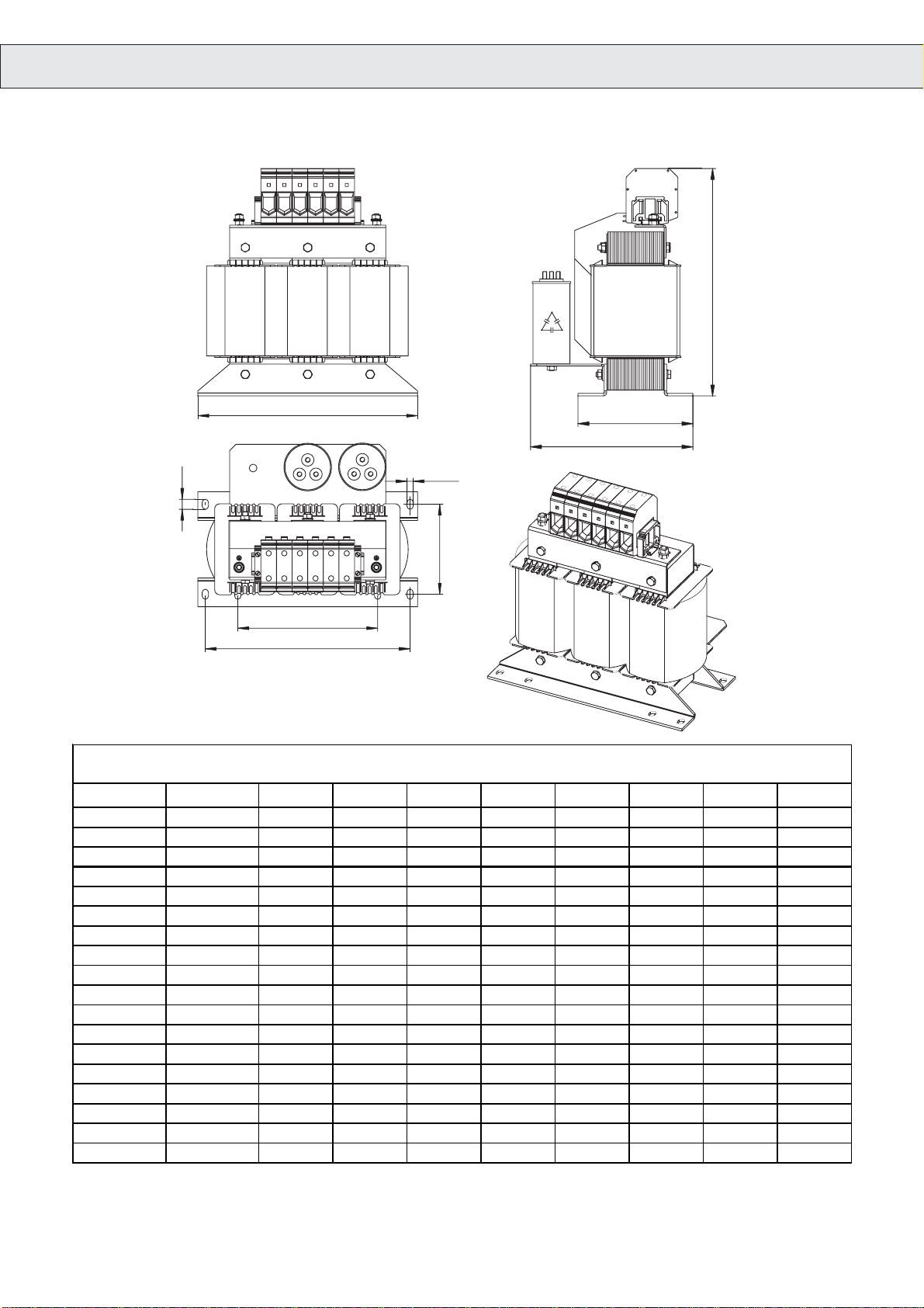
2.4 Dimensions
d2
T
B
H
H1
d1
L3
Dimensions
Part No.
12.Z1.C04-1000
13.Z1.C04-1000
14.Z1.C04-1000
15.Z1.C04-1000
16.Z1.C04-1000
17.Z1.C04-1000
18.Z1.C04-1000
19.Z1.C04-1000
20.Z1.C04-1000
21.Z1.C04-1000
22.Z1.C04-1000
23.Z1.C04-1000
24.Z1.C04-1000
25.Z1.C04-1000
26.Z1.C04-1000
27.Z1.C04-1000
28.Z1.C04-1000
29.Z1.C04-1000
L2
L1
B [mm] H [mm] H1 [mm] T [mm] L1 [mm] L2 [mm] L3 [mm] d1 [mm] d2 [mm]
219 120 169 202 201 136 90 7 12
243 114 190 245 225 144 86 7 12
291 118 192 278 273 185 86 7 12
291 138 212 240 273 185 105 10 18
352 143 215 315 328 224 103 10 16
352 168 240 343 328 224 128 10 16
352 184 256 324 328 224 144 10 16
352 192 268 325 328 224 152 10 16
388 184 240 337 364 248 144 10 16
412 192 311 385 388 264 152 10 16
412 214 378 404 388 264 175 10 16
480 212 337 408 450 316 163 12 20
552 242 481 472 516 356 182 14,5 24
552 272 511 468 516 356 212 14,5 24
552 292 530 491 516 356 232 14,5 24
552 312 551 473 516 356 253 14,5 24
660 272 496 506 620 460 212 14,5 24
660 332 562 512 620 460 272 15 24
GB - 8
Page 9

2.5 Description
The KEB harmonic filter is a new innovative solution, which can be already
assigned in the planning phase into the electrical system. The harmonic filter
enables the compliance of growing international standards to reduced harmonic
components.
The following belong to this standards:
- IEEE 519-1992 (USA)
- G5/4 Engineering Recommendation (GB)
- EN 610003-4 and EN 610003-12 (European Standard)
- EN 12015 (European lift norm)
- AS 2279 (Australian)
- COP, supply rules (Hongkong)
- Quality of Electric Energy Supply, Harmonics in Public Supply Networks
(China)
The following advantages are given by means of the special structure of the
harmonic filter:
- optimal filter effect
- compact structure, small space requirements for installation
- installation solution ready-to-connect
- clear reduction of the capacitive current during no-load operation
- no tendency to oscillation during load change
- significant smaller voltage drop compared to mains choke
- Increase of the inverter lifetime by means of the trapezoidal output voltage
and the square-wave current connected with it
- Reduction of THDI to
- optional THDI
- optional THDI
- large power range because parallel connection of filter modules is possible
- very high efficiency
The reduction of the THDI to the indicated value of
public supply system with a max.preloading of THDU = 2% and a ratio of shortcircuit power to connected power RSG = 66 min.
< 8%
< 15%; PWHD < 39%
< 5% (extreme requirements)
< 8% supposes a VDE conform
GB - 9
Page 10

Applications:
- Observance the standards
- smaller voltage drop compared to mains choke
- Reduction of effective input current (supply via generators )
- Protection of frequency inverter in case of bad mains (voltage overshoots)
- Protection of “non-rigid supply systems”
- Increasing DC link lifetime (several KEB COMBIVERT can be operated at
one filter.)
Optional:
- Thermal contact
- Option HF filter
- 3ph/ 230 VAC/ 500 VAC/ 690 VAC
- Housing type, mechanical structure IP23
Reactive-power compensation equipment without choke and resonance danger
Reactive-power compensation equipment are used in the power supply of
companies. Disturbances or damages at these units can have effects to the
power supply of the company and they can cause losses of production.
In practice many reactive-power compensation equipments without choke are
still used. Various problems can occur in this connection:
- direct resonance
- resonance danger
- switching transient
- interference of ripple control transmission
For the case that resonances occur it is not essential whether a company causes
itself disturbance of main supply network. The compensation power at the
transformer is decisive for the risk that resonances occur. The higher the power
the higher the resonance risk. An important factor for this is the harmonic
preloading in the ms level. The harmonic preloading is transferred by the
transformer and affects the ns level.
GB - 10
Page 11
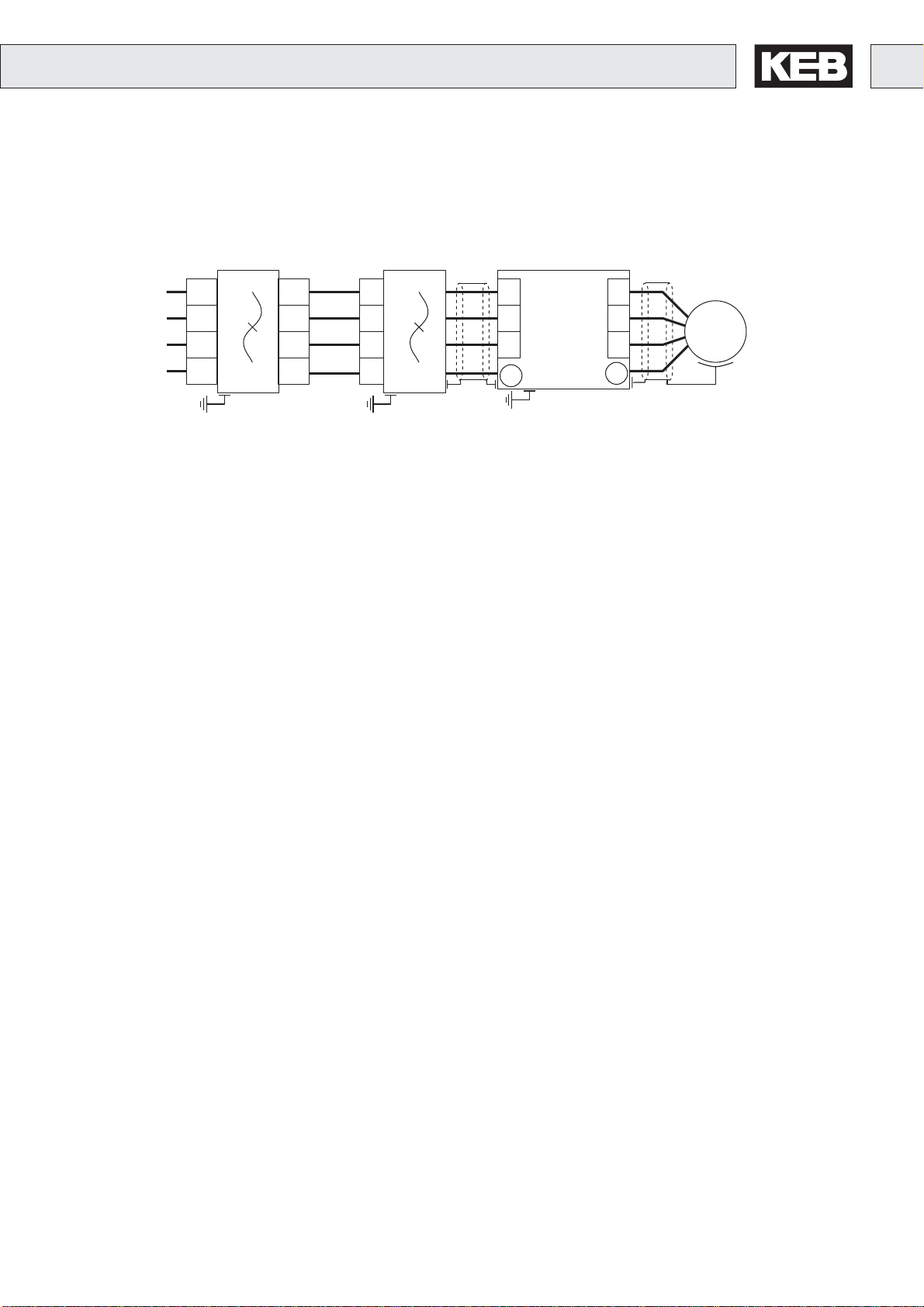
3. Installation
M
3~
3.1 Connection
KEB
Harmonic Filter
L1
L2
L3
PE
L1.1
L2.1
L3.1
PE
L1.2
L2.2
L3.2
PE
3.2 Installation Instructions
The KEB harmonic filter is to be used only as built-in unit. During installation pay
attention to the following:
- The distance to adjacent modules may not fall below 150 mm.
- A distance of 150 mm must be observed above and below the filter.
- Sufficient countermeasures must be taken against impurities of any kind.
- The permissible ambient temperatures may not be exceeded.
KEB
COMBILINE
HF-Filter
L1
L2
L3
PE
L1
L2
L3
PE
KEB
COMBIVERT
U
V
W
PE
The installation of the filter can be made in standing or lying position. The
arrangement of the capacitors is below or beside the choke. In order to avoid
damage or destruction of the capacitors by overheat of the choke the capacitors
may not be arranged above the choke!
GB - 11
Page 12
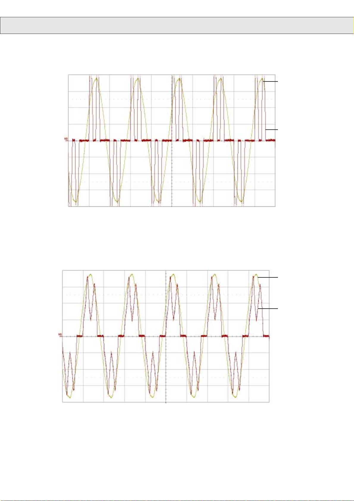
4. Oscillograms
Voltage and current at the mains
Voltage
Current
Without smoothing reactor high current peaks occur by no-limit loading of the DC link capacitors. Thus the increased disturbances of the
DC link voltage continue to the motor by manner of torque fluctuations.
Voltage
Current
Voltage and current with mains choke uk = 4%
With inductance (mains choke) the amplitudes of the currents are reduced due to the smoothing. The DC link voltage is smoother and thus
the lifetime of the capacitors is extended.
GB - 12
Page 13
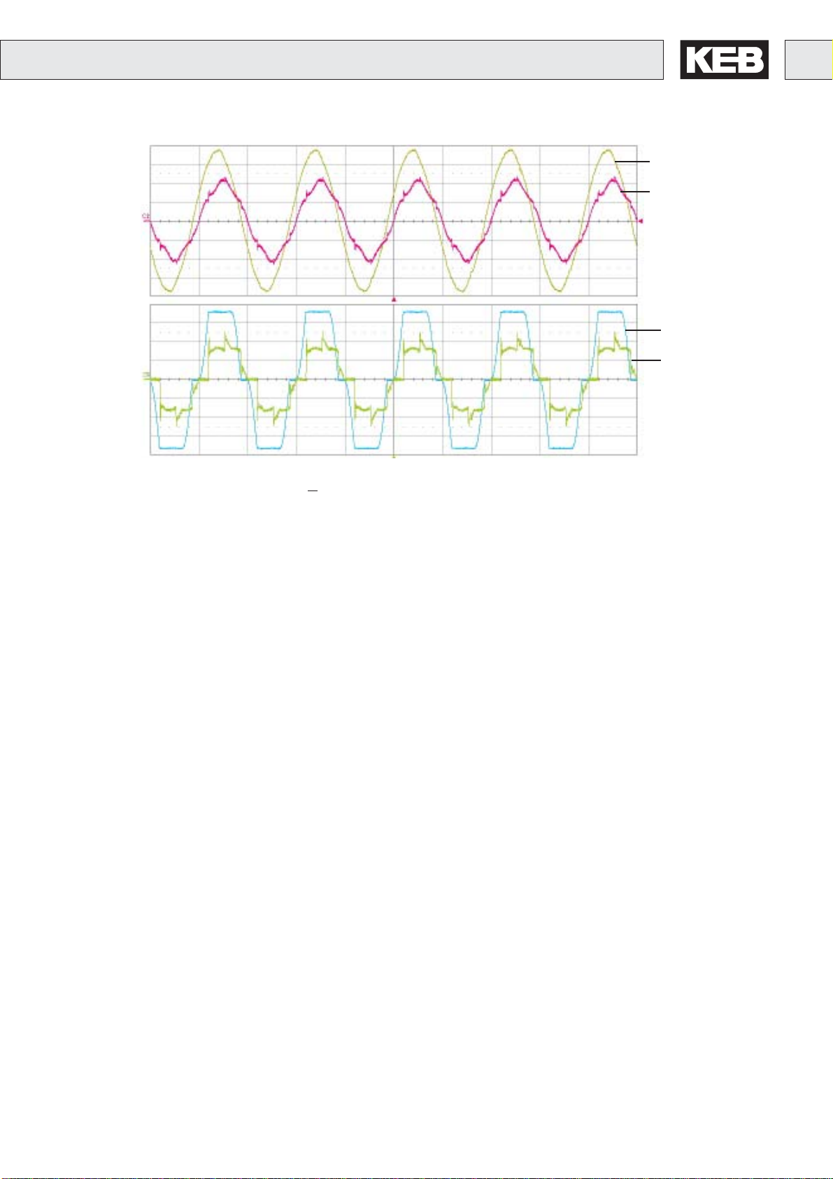
Input
Voltage
Current
Output
Voltage
Current
Voltage and current with the harmonic filter THD < 8%
With the harmonic filter and the line-side sinusoidal current the amplitudes of the currents are reduced again compared to the choke. The
output variables are nearly rectangular and they cause so a very smooth voltage in the DC link and an increased lifetime of the capacitors.
GB - 13
Page 14
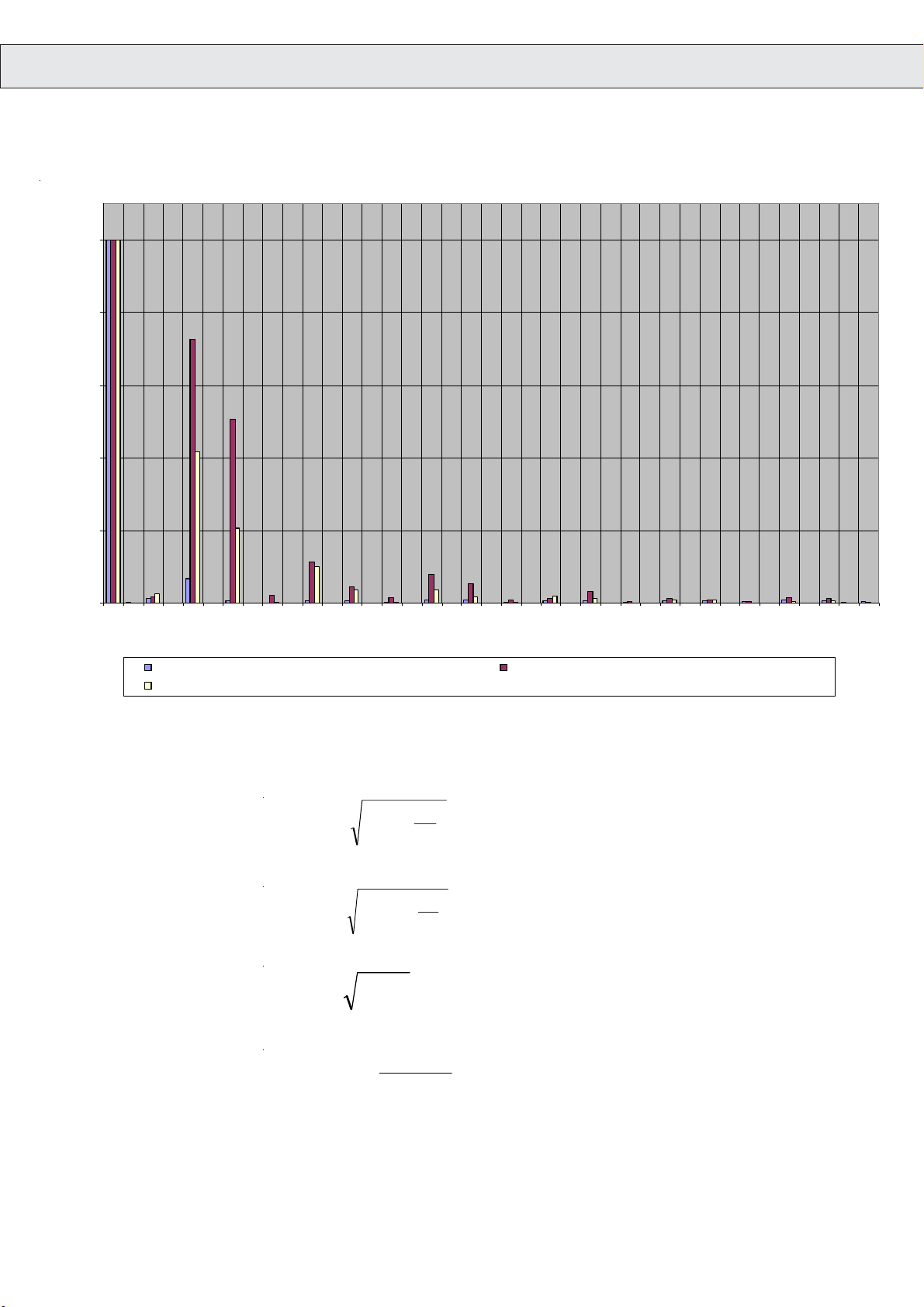
5. Annex
u
5.1 Fourier Analysis/ Spectrum
100
80
60
40
Strom I in % von IH01
20
0
1 2 3 4 5 6 7 8 9 101112131415161718192021222324252627282930313233343536373839
Ordnungszahl d er Obe rschwin gu ng
Spekt rum des E i ngangsstromes eines K EB OS F 8% THDI Spek t rum des E ingangsst rom es ei nes KEB FU ohne Drossel
Spekt rum des E i ngangsstromes eines K EB FU mi t Drossel
5.2 Formula
THD
PWHD
S
equ
THD
∑
∑
40
=
n
40
=
n
14
=
=
⎞
⎛
I
2
N
⎟
⎜
⎟
⎜
2
I
1
⎠
⎝
⎞
⎛
I
2
N
⎟
⎜
nPWHD
⎟
⎜
I
1
⎠
⎝
IUS **3=
eq
iequ
S
R
sce
R =
sce
sc
S
equ
GB - 14
Page 15

Page 16

Försterweg 36-38 • D-32683 Barntrup
fon: +49 5263 401-0 • fax: +49 5263 401-116
KEB Antriebstechnik GmbH & Co. KG
Wildbacher Str. 5 • D–08289 Schneeberg
fon: +49 3772 67-0 • fax: +49 3772 67-281
mail: [email protected]
KEB Antriebstechnik Austria GmbH
Ritzstraße 8 • A-4614 Marchtrenk
fon: +43 7243 53586-0 • fax: +43 7243 53586-21
Kostelni 32/1226 • CZ-370 04 Ceské Budejovice
fon: +420 38 7319223 • fax: +420 38 7330697
net: www. keb.at • mail: [email protected]
KEB Antriebstechnik
Herenveld 2 • B-9500 Geraadsbergen
fon: +32 5443 7860 • fax: +32 5443 7898
mail: [email protected]
KEB CHINA Karl E. Brinkmann GmH
(Xinmao Building, Caohejing Development Zone)
No. 99 Tianzhou Road (No.9 building, Room 708)
CHN-200233 Shanghai, PR. China
fon: +86 21 54503230-3232 • fax: +86 21 54450115
net: www.keb.cn • mail: [email protected]
KEB CHINA Karl E. Brinkmann GmH
No. 36 Xiaoyun Road • Chaoyang District
CHN-10027 Beijing, PR. China
fon: +86 10 84475815 + 819 • fax: +86 10 84475868
net: www.keb.cn • mail: [email protected]
KEB Antriebstechnik Austria GmbH
Organizacni slozka
Kostelni 32/1226
CZ-370 04 Ceske Budejovice
fon: +420 38 7699111 • fax: +420 38 7699119
mail: [email protected]
KEB España
C/ Mitjer, Nave 8 - Pol. Ind. LA MASIA
E-08798 Sant Cugat Sesgarrigues (Barcelona)
fon: +34 93 897 0268 • fax: +34 93 899 2035
mail: [email protected]
Société Française KEB
Z.I. de la Croix St. Nicolas • 14, rue Gustave Eiffel
F-94510 LA QUEUE EN BRIE
fon: +33 1 49620101 • fax: +33 1 45767495
net: www.keb.fr • mail: [email protected]
KEB (UK) Ltd.
6 Chieftain Buisiness Park, Morris Close
Park Farm, Wellingborough GB-Northants, NN8 6 XF
fon: +44 1933 402220 • fax: +44 1933 400724
net: www.keb-uk.co.uk • mail: [email protected]
net: www.keb.de • mail: [email protected]
Karl E. Brinkmann Gm bH
Via Newton, 2 • I-20019 Settimo Milanese (Milano)
fon: +39 02 33500782 • fax: +39 02 33500790
fon: +81 33 445-8515 • fax: +81 33 445-8215
Leidsevaart 126 •
fon: +31 23 5320049 • fax: +31 23 5322260
ul. Budapesztańska 3/16 • PL–80-288 Gdańsk
fon: +48 58 524 0518 • fax: +48 58 524 0519
Avenida da Igreja – Pavilão A n. º
fon: +351 252 371318 + 19 • fax: +351 252 371320
No.8, Lane 89, Sec.3; Taichung Kang Rd.
fon: +886 4 23506488 • fax: +886 4 23501403
fon: +82 2 6253 6771 • fax: +82 2 6253 6770
fon: +46 31 961520 • fax: +46 31 961124
fon: +1 952 224-1400 • fax: +1 952 224-1499
net: www.kebamerica.com • mail: [email protected]
KE B Italia S .r .l.
net: www.keb.it • mail: [email protected]
KEB - YAMAKYU Ltd.
15–16, 2–Chome, Takanawa Minato-ku
J–Tokyo 108-0074
mail: [email protected]
KEB Nederland
NL–2013 HD Haarlem
mail: [email protected]
KEB Polska
mail: [email protected]
KEB Portugal
261 Mouquim
P-4770 - 360 MOUQUIM V.N.F.
mail: [email protected]
KEB Taiwan Ltd.
R.O.C.-Taichung City / Taiwan
mail: [email protected]
KEB Korea Seoul
Room 1709, 415 Missy 2000
725 Su Seo Dong, Gang Nam Gu
ROK-135-757 Seoul/South Korea
mail: [email protected]
KEB Sverige
Box 265 (Bergavägen 19)
S-43093 Hälsö
mail: [email protected]
KEB A merica, Inc.
5100 Valley Industrial Blvd. South
USA-Shakopee, MN 55379
© KEB 00.U0.HE0-K310 11/2005
 Loading...