

Page 1
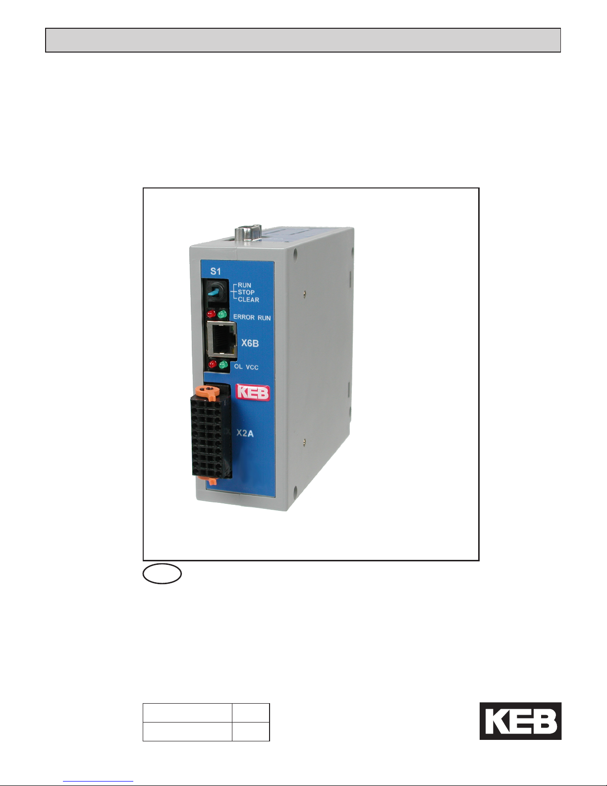
KEB COMBICONTROL
Mat.No. Rev.
00C6NEB-BA00 1D
GB
INSTRUCTION MANUAL
C6-COMPACT
C6-COMPACT II
C6
Page 2
GB - 2
Preface
KEB reserves the right to change/adapt specications and technical data without prior notice.
The safety and warning directions specied in this manual is not exhaustive. The manual
and the information contained in it is made with care. KEB don´t accept a guarantee for
misprint or other errors or resulting damages.
The marks and product names are trade marks or registered trade marks of the respective
title owners.
This instruction manual describes the software state 3.4.1.3 from 07/2012. The information
contained in the technical documentation, as well as any user-specic advice in spoken and
written and through tests, are made to best of our knowledge and information about the application. However, they are considered for information only without responsibility. This also
applies to any violation of industrial property rights of a third-party. Inspection of our units in
view of their suitability for the intended use must be done generally by the user. Inspections
are particularly necessary, if changes are executed, which serve for the further development
or adaption of our products to the applications (hardware, software or download lists). Inspections must be repeated completely, even if only parts of hardware, software or download
lists are modied.
Application and use of our units in the target products is outside of our control and
therefore lies exclusively in the area of responsibility of the user.
Danger
Is used when the life or health of the user is in danger or considerable damage to property can occur.
Warning
Caution
Attention
Is used when a measure is necessary for safe and disturbance-
free operation.
observe at
all costs
Information
Is used, if a measure simplies the handling or operation of the
unit.
Aid
Tip
Copyright
The customer may use the instruction manual as well as further documents or parts from it for
internal purposes. Copyrights are with KEB and remain valid in its entirety.All rights reserved.
KEB®, COMBIVERT®, KEB COMBICONTROL® and COMBIVIS® are registered trademarks
of Karl E. Brinkmann GmbH.
Other wordmarks or/and logos are trademarks (TM) or registered trademarks (®)
of their respective owners and are listed in the footnote on the first occurrence.
When creating our documents we pay attention with the utmost care to the rights of third
parties.Should we have not marked a trademark or breach a copyright, please inform us in
order to have the possibility of remedy.
Page 3

GB - 3
Table of Contents
1. Description of the Unit............................................................................. 4
1.1 Intended use ...........................................................................................................4
1.2 Assembly ................................................................................................................4
1.3 CE-certications ....................................................................................................4
1.4 Unitidentication ..................................................................................................5
1.5 Technical data ........................................................................................................5
1.6 Accessory ...............................................................................................................7
2. Functional Description ............................................................................ 8
2.1 Real-time clock ......................................................................................................8
2.2 HSP5/485-interfaces to the inverter/servo axes ..................................................8
2.2.1 View of the inverter interfaces X1A...X1D for the axes 1..4 .....................................9
2.2.2 Assignment of the HSP5/485 interfaces ..................................................................9
2.2.3 HSP5 Operator with screw terminal (00F5060-9001) ............................................10
2.2.4 HSP5 Operator with RJ45 socket (00F5060-9002) ...............................................10
2.2.5 Adapter cable HSP5 interface operator ................................................................. 11
2.2.6 Comparison of the standards .................................................................................11
2.3 Voltage supply and digital inputs and outputs .................................................12
2.3.1 Assembly of the wires ............................................................................................12
2.3.2 Voltage supply of the control ..................................................................................13
2.3.3 Voltage supply for the inputs and outputs ..............................................................14
2.3.4 Digital inputs (X2.11…14) ......................................................................................14
2.3.5 Digital outputs (X2.15…18) ....................................................................................15
2.4 The operating unit ...............................................................................................16
2.5 Serial interface (X6A) ...........................................................................................16
2.6 Ethernet interface (X6B) ......................................................................................17
2.7 Ethernet interface (X6C) ......................................................................................17
2.8 Description of the LED’s .....................................................................................17
2.9 Multi-function switch/button S1 .........................................................................18
2.10 File system ...........................................................................................................18
2.10.1 Internally Ram-Memory .........................................................................................18
2.10.2 Internal ash memory ............................................................................................18
2.11 Fieldbus interface ................................................................................................20
2.11.1 Fieldbus interface PROFIBUS DP .........................................................................20
2.11.2 CAN Bus interface .................................................................................................21
2.11.3 INTERBUS-Interface .............................................................................................22
3. Software .................................................................................................. 23
3.1 Programming system ..........................................................................................23
3.1.1 Boot projects ..........................................................................................................23
3.2 Parameterizing system .......................................................................................23
3.3 Parameter description .........................................................................................24
3.3.1 Ethernet Parameter ...............................................................................................24
3.3.2 Real-time clock ......................................................................................................25
3.3.3 Userdenition parameter .......................................................................................26
3.3.4 Flash le system ....................................................................................................26
3.3.5 Debugging .............................................................................................................27
3.3.6 System parameter .................................................................................................27
Page 4

GB - 4
KEB COMBICONTROL
1. Description of the Unit
1.1 Intended use
KEB COMBICONTROL C6-COMPACT is a programmable control with direct connection
upto four KEB frequency inverters/servo axes of the series F5. The connection to the axes
is created as HSP5/485. All axes can be operated directly and synchronously with an inexpensive operator with this fast, reliable connection. Cycle times down to one millisecond are
realizable. Additionally the connection to the axes can also be done via EtherCAT®1, whereby
C6 serves as EtherCAT® master. The axis control is programmed with the uniform IEC 61131-3
programming system KEB COMBIVIS Studio 6.
KEB COMBICONTROL C6 COMPACT II is an enhanced programmable controller with a high
performance CPU and oating point unit (FPU). Program- and calculation function operation
is approx.5 times faster than at C6 COMPACT. The ash le system (drive C:) offers faster
access and more capacity (256 MB).
1.2 Assembly
The control consists of following modules:
• CPU and memory
• internal ash le system
• Switched-mode power supply
• Real-time clock
• HSP5/485 interfaces to the inverter/servo axes
• Ethernet interfaces
• serial interface
• Control and error LED’s
• RUN/Reset switch
• Voltage supply connection
• four digital inputs
• four digital outputs
• Field bus interface (optional)
1.3 CE-certications
This unit was tested in accordance with the generic standard EN 61000-6-2 in the range of
noise immunity and corresponds to the EMC directive 89/336/EWG with changes/extensions.
1
EtherCAT® is registered trademark and patented technology, licensed by Beckhoff
Automation GmbH, Deutschland
Page 5
GB - 5
KEB COMBICONTROL
1.4 Unitidentication
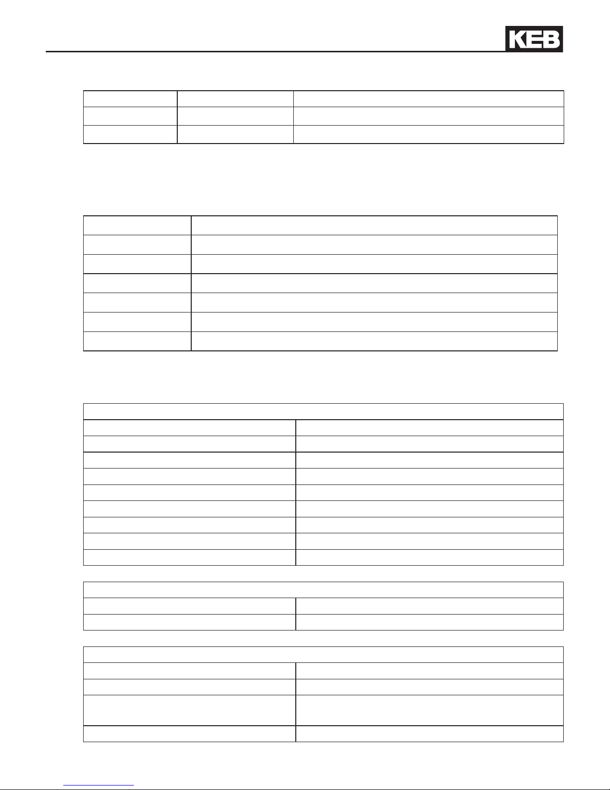
C6 Material number Description
Compact
00C6BA1-(x)A(y)0 4DI/4DO
COMPACT II
00C6BD1-(x)C(y)0 4DI/4DO
(x) = eldbus module: A = no, B = PROFIBUS slave, C = CAN, D = INTERBUS slave
(y) = soft option: A = no, B = soft motion
Examples:
00C6BA1-AAB0 C6-Compact 4DI/4DO + soft motion
00C6BA1-BAB0 C6-Compact 4DI/4DO + PROFIBUS slave + soft motion
00C6BA1-CAA0 C6-Compact 4DI/4DO + CAN
00C6BA1-DAA0 C6-Compact 4DI/4DO + INTERBUS slave
00C6BD1-ACA0 C6-Compact II 4DI/4DO
00C6BD1-BCA0 C6-Compact II 4DI/4DO + PROFIBUS Slave
00C6BD1-CCB0 C6-Compact II 4DI/4DO + CAN + Softmotion
1.5 Technical data
General
Dimensions (HxBxT) 125 x 44 x 144 mm
Weight approx. 260 g
Installation method 35 mm Mounting rail
Grounding via terminal strip or plug-in contact
Protective system (EN 60529): IP20
Operation temperature -10…45 °C (14…113 °F)
Storage temperature -25…70 °C (-13…158 °F)
Climatic category (EN 60721-3-3): 3K3
Environment (IEC 664-1) Pollution degree 2
Control
Operating voltage control (US) 18…30 V DC ±0 %
Power input control 3 W max.
Digital inputs/outputs
Wiring system cage-clamp terminals
Operating voltage inputs/outputs (UM) 18…30 V DC ±0 %
Output current max. 0.7 A per channel, short-circuit proof, free-
wheeling diode integrated
Input voltage/current according to IEC 61131-2 Type 1
Page 6
GB - 6
KEB COMBICONTROL
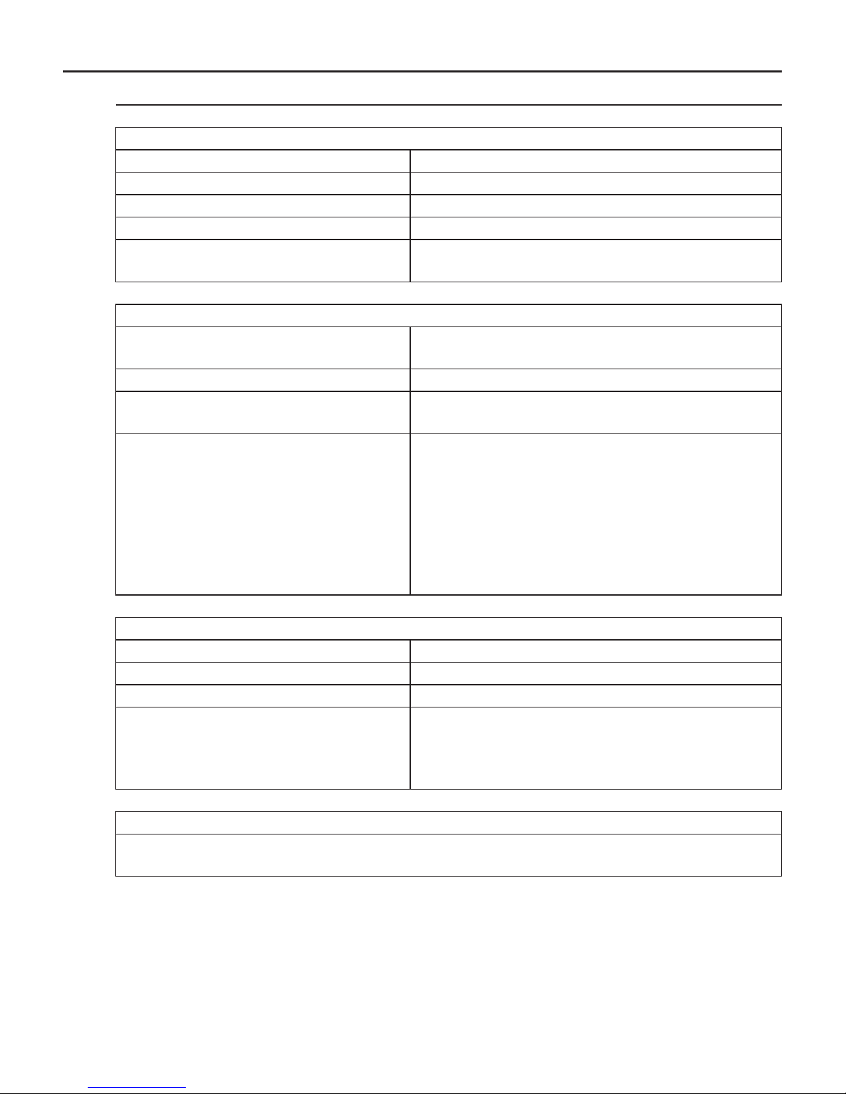
Axis interface X1A ... X1D
Type HSP5/485
Connector RJ-45, 8-pole, screened
Cable Cat5, max. 100 m
Speed 38.4…250 kBaud
Using Connection to KEB F5 inverter/servo, process
data transmission, communication channel
Ethernet interfaces X6B, X6C
Type IEEE802.3
10/100BaseTx
Connector RJ-45, 8-pole, screened
Speed 10/100 MBaud
autocrossover
Using Connection to programming system (debugging,
visualization).
Connection to parameterizing system (control
and axis adjustment, scope).
Connection to any devices
(SysSocket). Die 2. Ethernet interface X6C is
only accessible by the IEC program and is used
e.g. for the EtherCAT master.
Serial interface
Type DIN66019II, RS232, RS485 full/half duplex
Connector D-Sub 9 female
Speed 9.6…115.2 kBaud
Using Connection to parameterizing system
(control and axis adjustment, scope).
Connection to any devices
(SysCom).
Memory of the programming system
The program memory size (code, data, ags, input, output) is not limited and depends
only on the available free total memory (max. 32 MBytes).
Page 7
GB - 7
KEB COMBICONTROL
1.6 Accessory
Operators Material number
F5 HSP5/485, screw terminal 00F5060-9001
F5 HSP5/485, RJ45 00F5060-9002
Connection cable Material number
Cable RS232 for COMBIVIS 0058025-001D
Cable RJ45 open end (for operator -9001), 2,5 m 00F50C3-2025
Patch cable RJ45 (for operator -9002), 5 m 00F50C3-1050
Page 8

GB - 8
KEB COMBICONTROL
2. Functional Description
The C6 compact is mounted on a 35 mm mounting rail. The earthing occurs with a plug-in
contact or terminal connection X2.19/20.
2.1 Real-time clock
The integrated realtime clock is maintenance-free (no battery) and operates without power
supply for approx.30 days. After this it must be adjusted again. A read out parameter indicates
the validity of the date and time. The control shall remain switched on min. 30 minutes for
complete loading. Leap years are recognized automatically up to the year 2099. Date and
time can be read and set via COMBIVIS or the control program (library „SysTime“).
2.2 HSP5/485-interfaces to the inverter/servo axes
Up to four KEB COMBIVERT F5 can be connected via the terminals X1A to X1D. The
connection occurs via reliability RS485 cables, which can be up to 100 m long. A shielded
standard cable with RJ-45 connector is used on the control side and appropriate operator on
the frequency inverter/servo. The type of communication is determined by the IEC program,
see library description and demo program HSP5_Master. This means that no connection to
the axis is possible without IEC control program.
Page 9
GB - 9
KEB COMBICONTROL
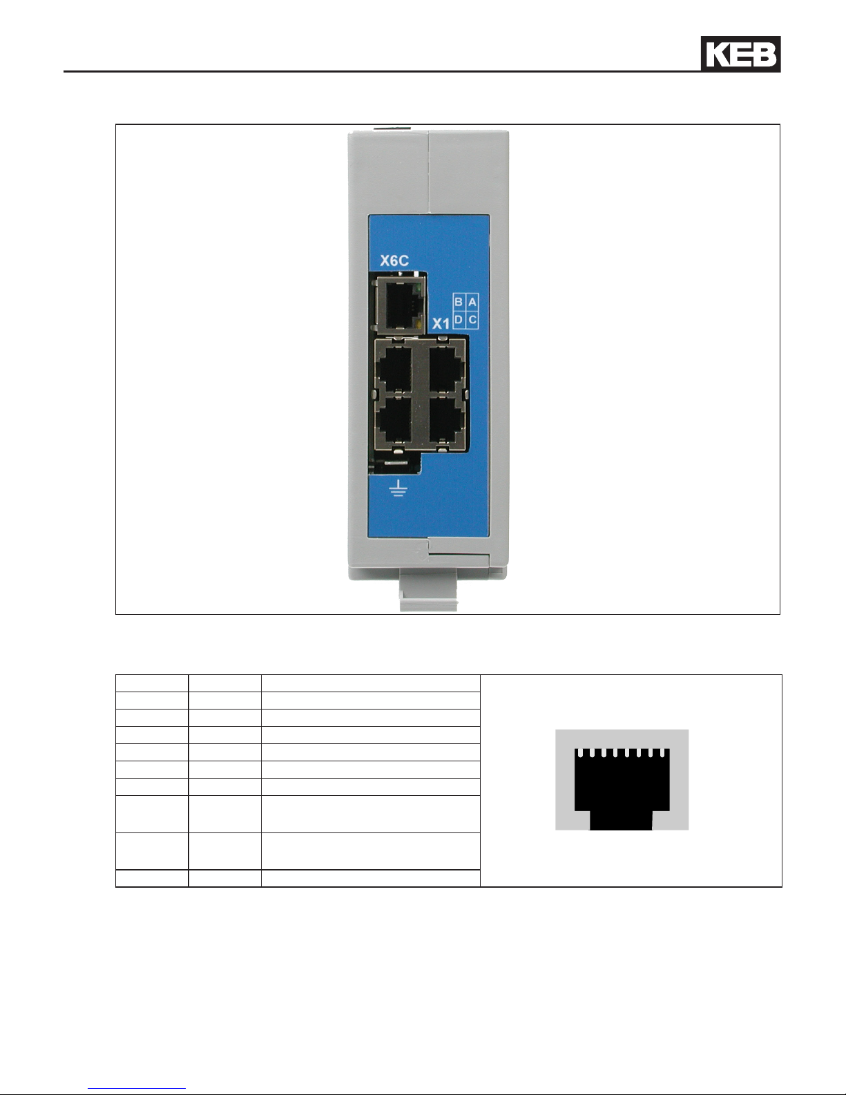
2.2.1 View of the inverter interfaces X1A...X1D for the axes 1..4
X1B (axis 2) —— —— X1A (axis 1)
X1D (axis 4) —— —— X1C (axis 3)
2.2.2 Assignment of the HSP5/485 interfaces
X1A…D Name Description Socket (top view)
1 TXD+ Transmission signal+
1 8
2 TXD- Transmission signal-
3 GND Reference potential
4 RXD+ Receive signal+
5 RXD- Receive signal6 GND Reference potential
7 EnTXD+ Handshake transmission
signal+
8 EnTXD- Handshake transmission
signal-
- Shielding shielding
Page 10
GB - 10
KEB COMBICONTROL
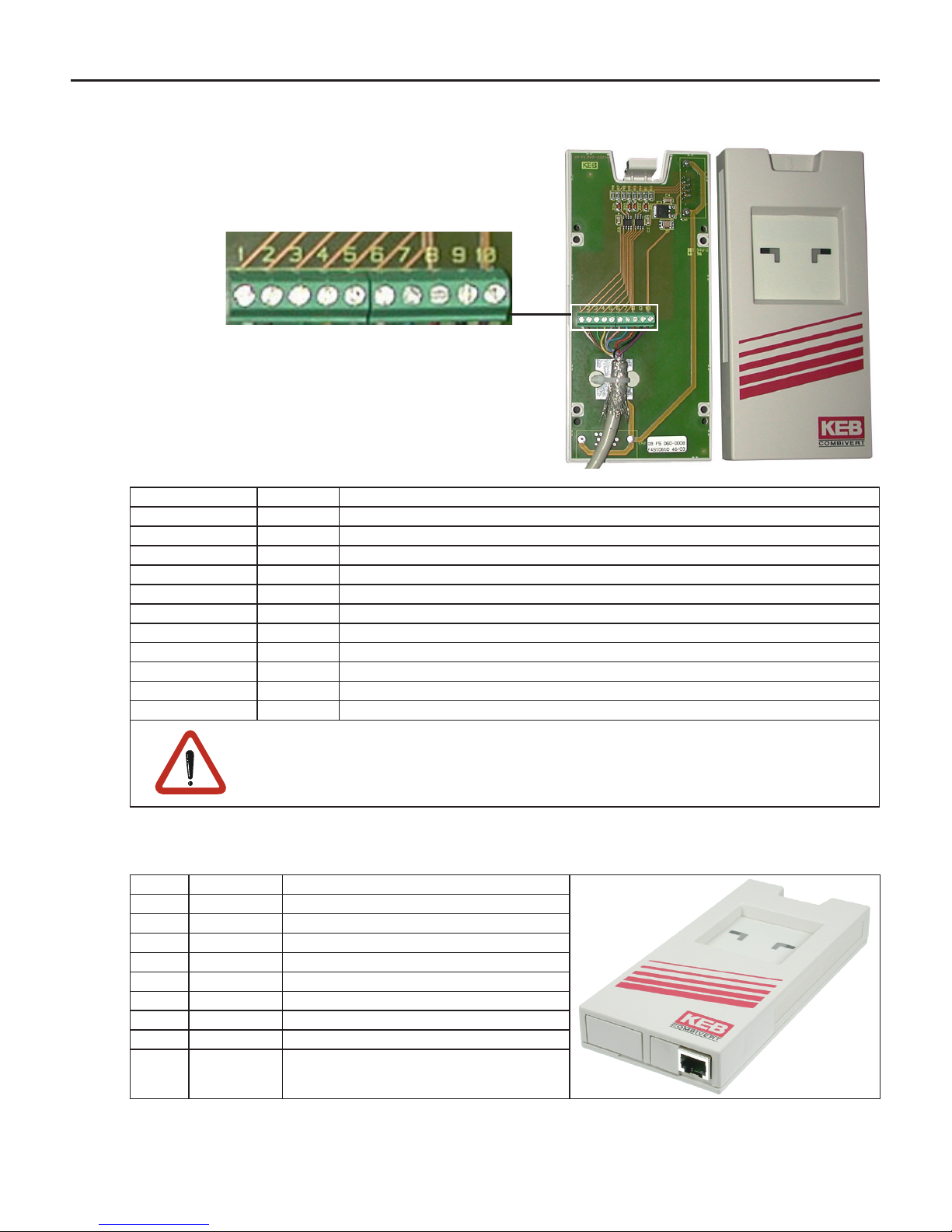
2.2.3 HSP5 Operator with screw terminal (00F5060-9001)
X6E Name Description
1 TXD- Transmission signal-
2 TXD+ Transmission signal+
3 RXD- Receive signal4 RXD+ Receive signal+
5 EnTXD- Handshake transmission signal6 EnTXD+ Handshake transmission signal+
7 EnRxD- Handshake receive signal8 EnRxD+ Handshake receive signal+
9 GND Reference potential
10 VCC +24 V voltage output
- Shielding Shielding (see gure)
No cables may be connected to terminal VCC. High voltage can destroy
the interface in the control.
2.2.4 HSP5 Operator with RJ45 socket (00F5060-9002)
RJ45 Name Description
1 RXD+ Receive signal+
2 RXD- Receive signal-
3 GND Reference potential
4 TXD+ Transmission signal+
5 TXD- Transmission signal6 GND Reference potential
7 EnRxD+ Handshake receive signal+
8 EnRxD- Handshake receive signal-
- Shielding shielding
The connection to the control is realized with a commercial CAT5 Patch cable for this operator.
X6E
Page 11
GB - 11
KEB COMBICONTROL
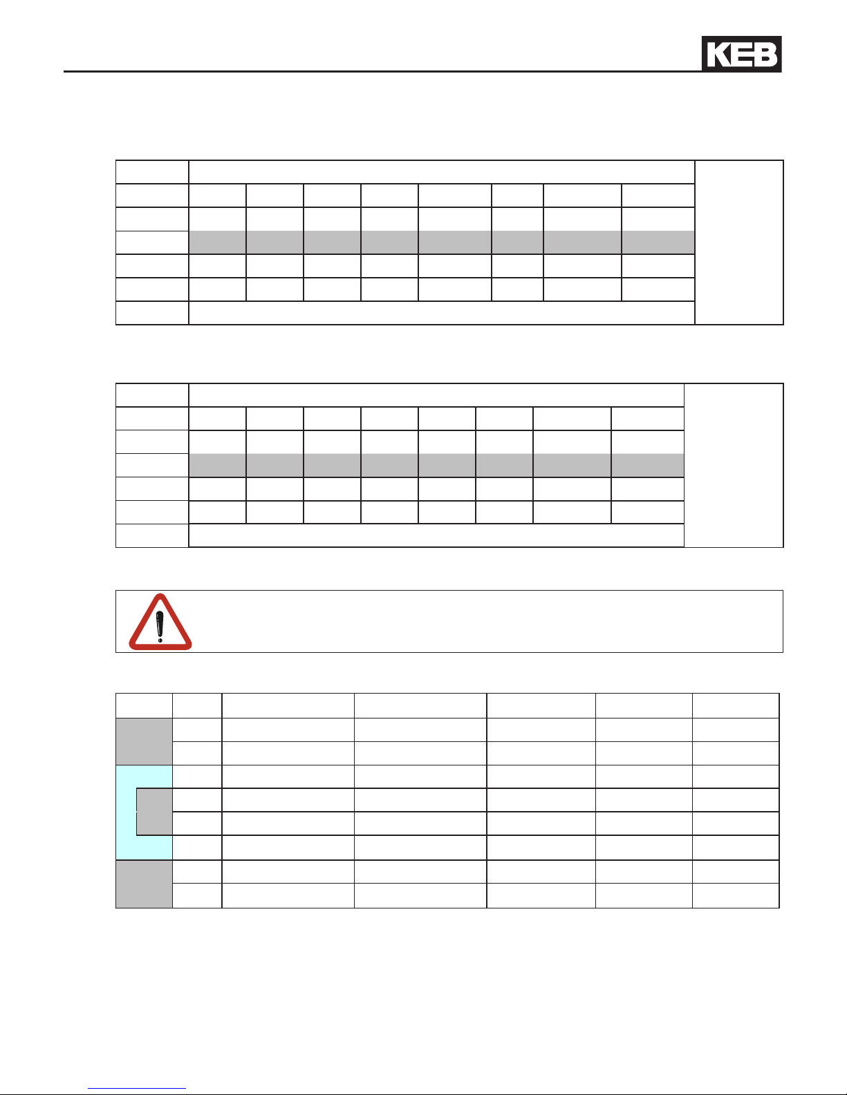
2.2.5 Adapter cable HSP5 interface operator
Screw terminal:
Color see below
C6 PCC
X1A…H
Signal TXD+ TXD- GND RXD+ RXD- GND EnTXD+ EnTXD-
PIN 1 2 3 4 5 6 7 8
| | | | | | | |
PIN 4 3 9 2 1 9 8 7
Operator
X6E
Signal RXD+ RXD- GND TXD+ TXD- GND EnRxD+ EnRxD-
Color see below
RJ45 connection:
Color see below
C6 PCC
X1A...H
Signal TXD+ TXD- GND RXD+ RXD- GND EnTXD+ EnTXD-
PIN 1 2 3 4 5 6 7 8
| | | | | | | |
PIN 1 2 3 4 5 6 7 8
Operator
RJ45
Signal RXD+ RXD- GND TXD+ TXD- GND EnRxD+ EnRxD-
Color see below
In case of production of own connecting cables please pay attention that the
signal pairs (e.g. TxD+ and TxD -) are assigned to the corresponding twisted
cables (e.g. green and green/white). Connect unused scores always to GND.
2.2.6 Comparison of the standards
Pair PIN EIA/TIA 568B EIA/TIA 568A DIN 47100 IEC 189.2 USOC
3 1 orange/white green/white green red black
3 2 orange green yellow orange yellow
2 3 green/white orange/white gray black orange
1 4 blue blue brown blue red
1 5 blue/white blue/white white white green
2 6 green orange pink green brown
4 7 brown/white brown/white blue yellow gray
4 8 brown brown red brown blue
Page 12
GB - 12
KEB COMBICONTROL
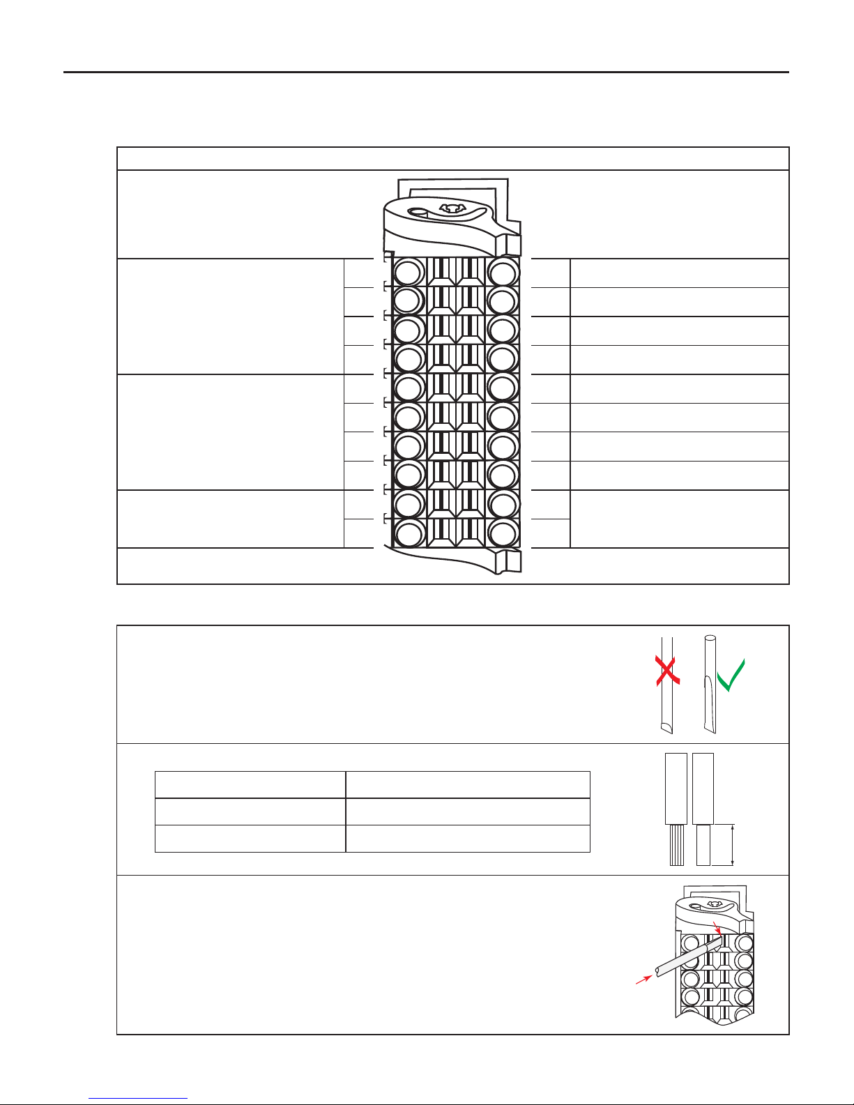
2.3 Voltage supply and digital inputs and outputs
Figure 2.3 Socket X2
Voltage supply Digital in- and outputs
+ Voltage input (UM)
(internally interconnected)
1 11
Digital input 0
2 12
Digital input 1
3 13
Digital input 2
4 14
Digital input 3
- Voltage input (UM)
(internally interconnected)
5 15
Digital output 0
6 16
Digital output 1
7 17
Digital output 2
8 18
Digital output 3
+ Voltage input (US)
9 19
PE
- Voltage input (US)
10 20
2.3.1 Assembly of the wires
Required tools:
Screw driver
SD 0,4 x 2.5 (DIN 5264)
1. Strip cable
Cable permissible cross-section
exible 0,2…1 mm
2
Wire-end ferrule 0.13…0.34 mm
2
7mm
2. Plug screw driver mid into the square slot
Page 13
GB - 13
KEB COMBICONTROL
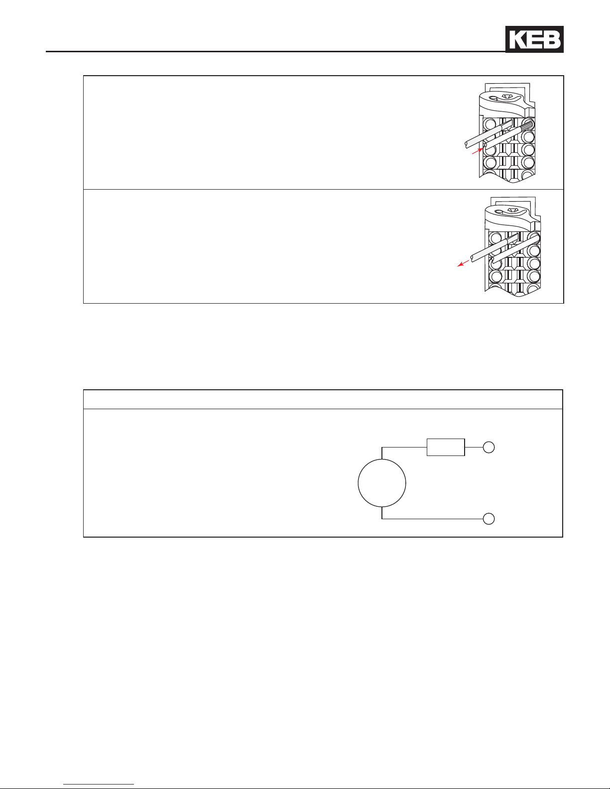
3. Plug cable into the round slot, that no wires can be seen
from the outside.
4. Remove screw driver and check if cables are xed.
2.3.2 Voltage supply of the control
The voltage for supply of the control (US) occurs via terminals X2.9 and X2.10 in accordance
with picture 2.3.2 and is electrically insulated from UM. If the control is supplied with voltage,
the VCC-LED ashes (green).
Picture 2.3.2 Voltage supply of the control
U = 18…30 V DC ±0 %
F1 = 2 A type gG
+
-
U
F1
X2.9
X2.10
Page 14
GB - 14
KEB COMBICONTROL
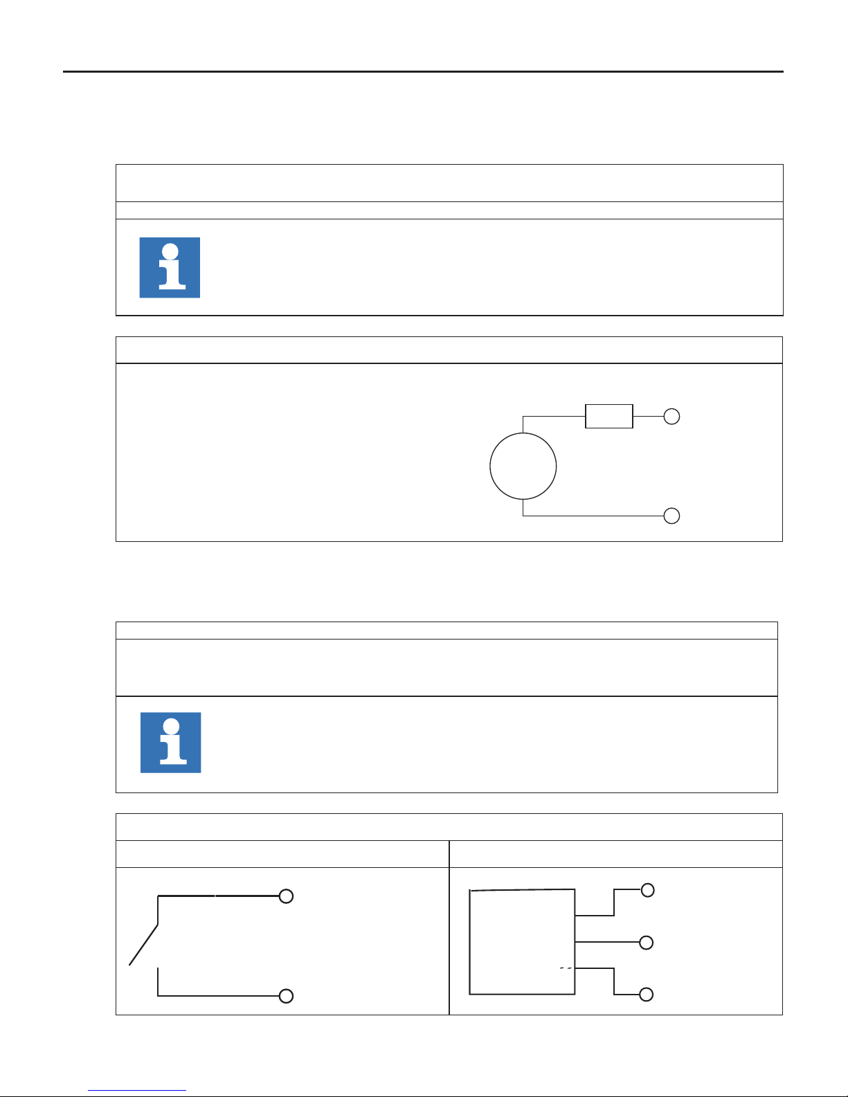
2.3.3 Voltage supply for the inputs and outputs
The voltage for supply of the digital inputs and outputs (UM) occurs via the terminals X2.1 to
X2.8 in accordance with picture 2.3.3 and is electrically insulated from US.
%IB1
Is set in case of overload at one or several outputs. Additionally the OL-LED
(red) is set.
%IB2 Condition of the supply voltage in/outputs (UM)
Address can be changed in the unit editor.
Picture 2.3.3 Voltage supply for the inputs and outputs
U = 18…30 V DC ±0 %
F2 = 6.3 A type gG
+
-
U
F2
X2.1...4
X2.5...8
2.3.4 Digital inputs (X2.11…14)
The digital inputs are potential-free to the control voltage US.
4 digital outputs 0...3
%IB0 Condition of the digital inputs 0…3.
Address can be changed in the unit editor.
Picture 2.3.4 Connection of the digital inputs
Potential-free connection Connection e.g. via PLC
X 2.2 (+UM)
X 2.12 (I1)
+
-
X2.2 (+UM)
X2.5 (- UM)
X2.12 ( I1 )
П
Page 15
GB - 15
KEB COMBICONTROL
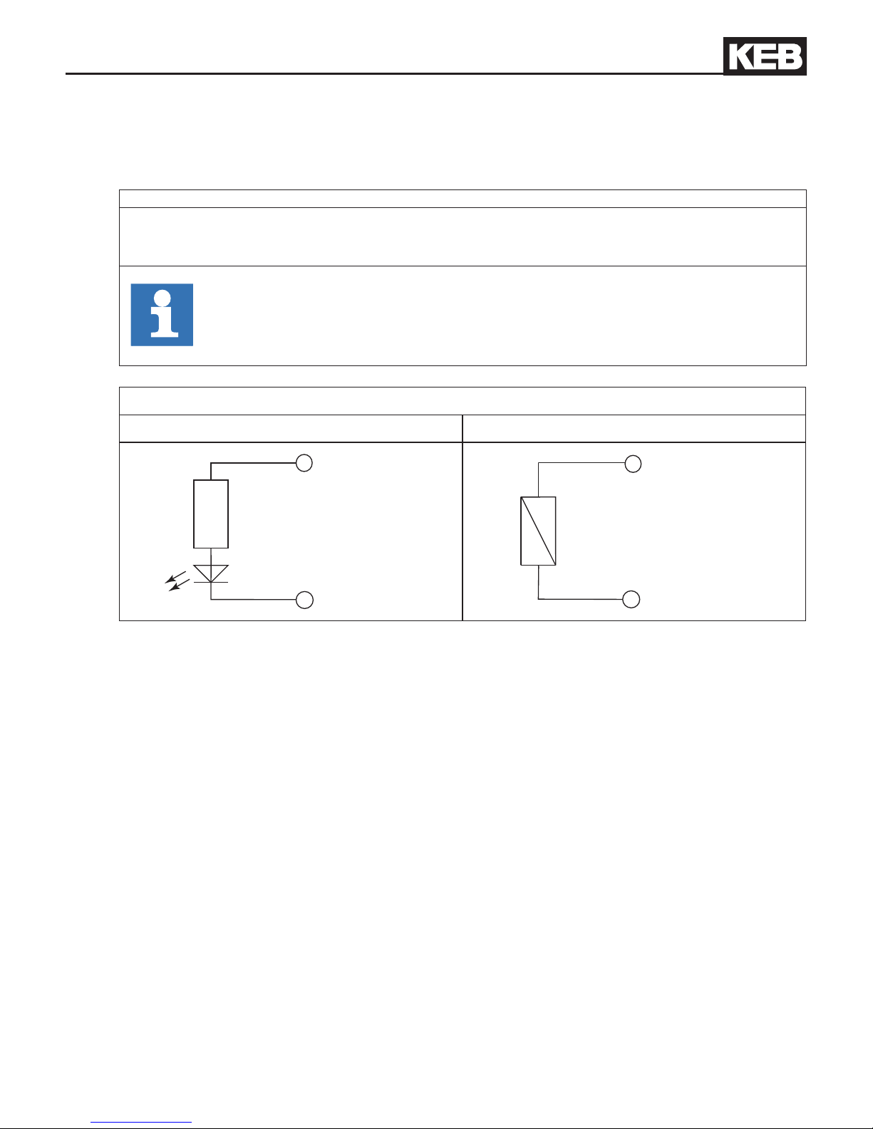
2.3.5 Digital outputs (X2.15…18)
The digital outputs are potential-free to the control voltage US. A free-wheeling diode is integrated in the unit, so that no external wiring is necessary at inductive load.
4 digital outputs 0...3
%QB0 Condition of the digital inputs 0…3.
Address can be changed in the unit editor.
Picture 2.3.5 Connection of the digital outputs
Ohmic load Inductive load
X 2.16 (O1)
X 2.6 (- UM)
X 2.17 (O2)
X 2.7 (- UM)
Page 16
GB - 16
KEB COMBICONTROL
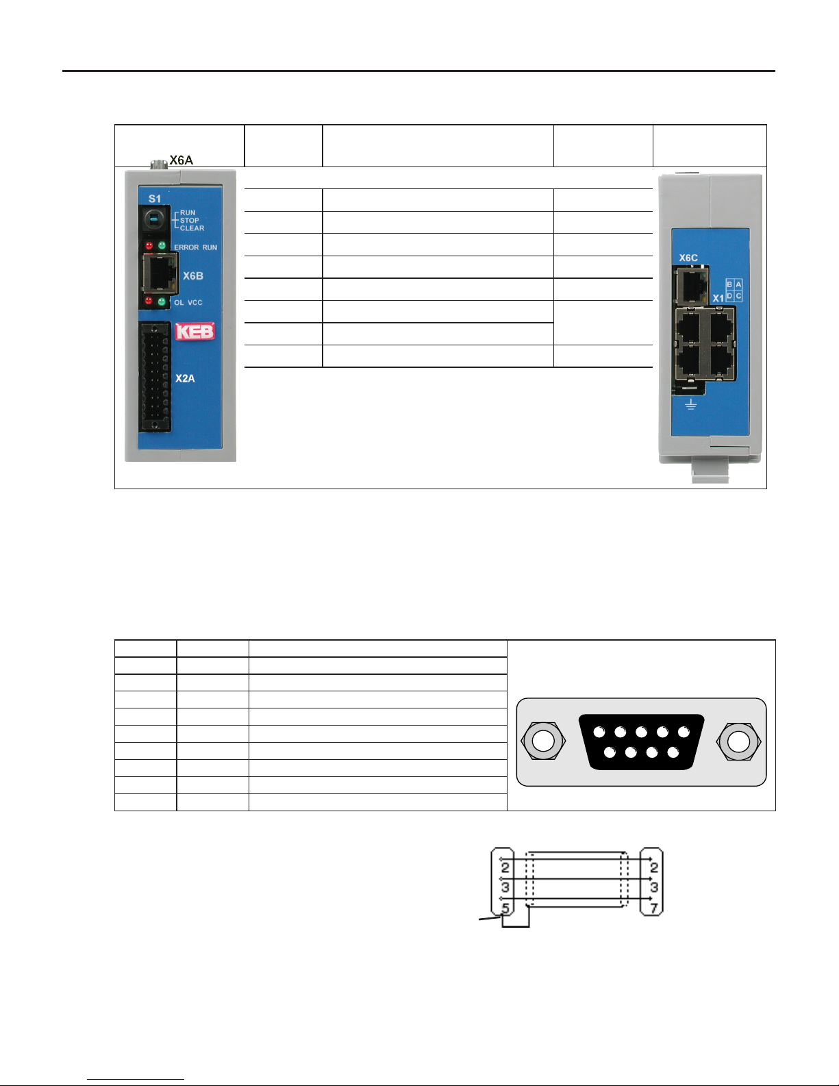
2.4 The operating unit
View Front Name Function Addition View from the
bottom
S1 Multi function switch/button
RUN Run-LED green
ERROR ERROR-LED red
OL Overload red
VCC Voltage supply (US) green
X6A Serial interface COMBIVIS
X6B Ethernet interface
COMBIVIS/
CoDeSys
X6C Ethernet interface
X1A…D Axis interfaces
2.5 Serial interface (X6A)
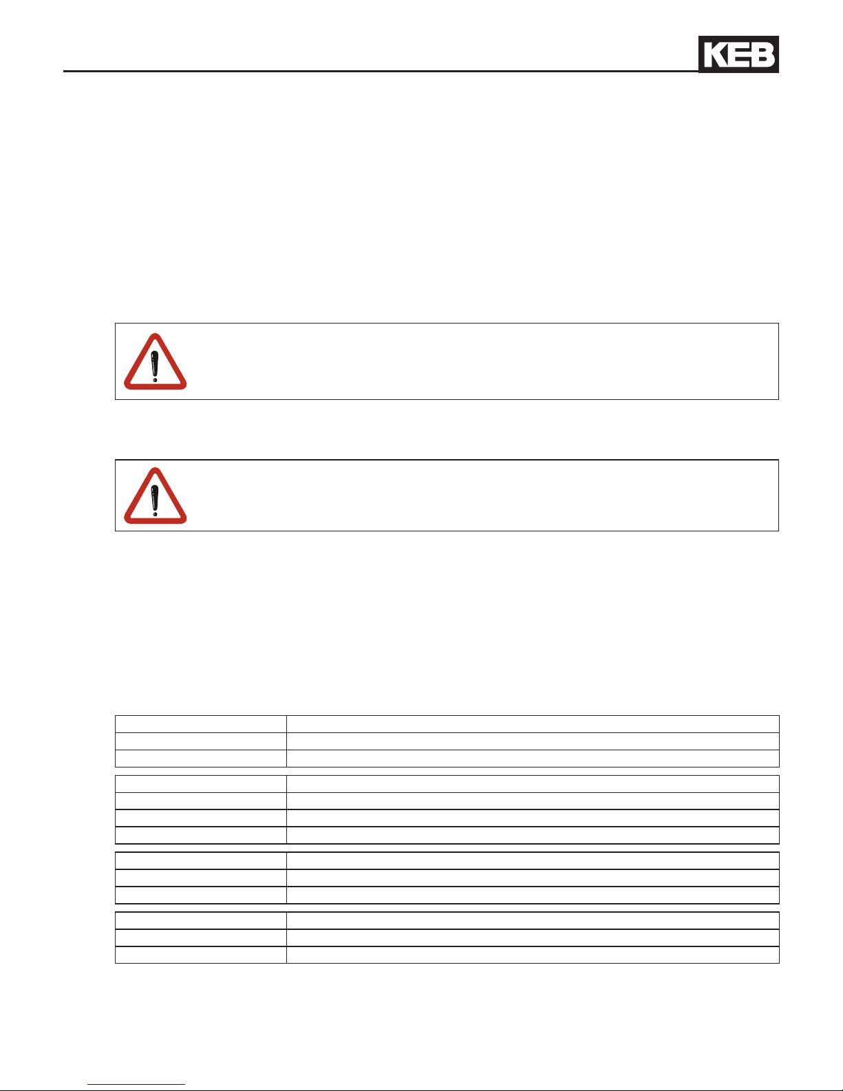
The socket X6A is a serial RS232/485 interface. It serves for the connection of the control
with a PC or other operating units via the protocol DIN66019II, whereby the node address
is set to 0. Alternatively any access to this interface can be done by the IEC control program
and this offers different protocol variants (library „SysCom“).
X6A Name Description SUB-D9 socket
1 PGM No wiring ! (top view)
2 TxD Transmission signal RS232
54321
9876
3 RxD Receive signal RS232
4 RxD-A Receive signal RS485 A
5 RxD-B Receive signal RS485 B
6 PGM+ No wiring !
7 DGND data reference potential
8 TxD-A Transmission signal RS485 A
9 TxD-B Transmission signal RS485 B
9-pol. SUB-D coupling 9 pole SUB-D connector
Part.No.: 0058025-001D
RS 232 cable
2.8 m
Housing (PE)
PC C5
Page 17
GB - 17
KEB COMBICONTROL
2.6 Ethernet interface (X6B)
The standardized 10/100 base-T interface supports the protocols TCP/IP and UDP/IP. The
following ports have these functions:
The run-time system uses ports 1740-1743 for out-connection. Firmware parameters are
available on port 8001. TCP or UDP is possible as protocol, whereby encapsulated DIN66019II
data telegrams will be transferred (the node address is set to 0). The le system can be read/
written via port 8002 (only UDP) with KEB ftp-le transfer protocol (writing only with supervisor
password). Furthermore access to other ports of this interface can be done via the IEC control
program (library SysSocket ").
A correct adjustment is important for the programming system connection. The
used IP address can be adjusted with parameter Et.01. The subnet mask is
adjusted with parameter Et.11.
A power on reset is necessary after the change!
The interface supports automatic polarity detection, Auto-crossover and automatic speed
detection, adjustable with parameter Et.15.
Protect C6 against unauthorized access.
Each user within a network can take access to the control with knowledge of the IP address.
For protection the write access can be limited via port 8001 with parameter et.09.
2.7 Ethernet interface (X6C)
The standardized 10/100 base Tx-Ethernet interface is protocol independent accessible via the
IEC control program. The data are exchanged here by system libraries (library „SysEthernet
“) or by inserting an EtherCat master.
2.8 Description of the LED’s
Run-LED green
off PLC program stopped or not available
on PLC program in run mode
ERROR-LED red
off O.K.
on Program error
fast blinking Hardware error, control must be restarted
OL-LED red
off no error at the outputs
on Overload or short circuit at the outputs
VCC-LED green
off No power supply
on Voltage supply available
Page 18
GB - 18
KEB COMBICONTROL
2.9 Multi-function switch/button S1
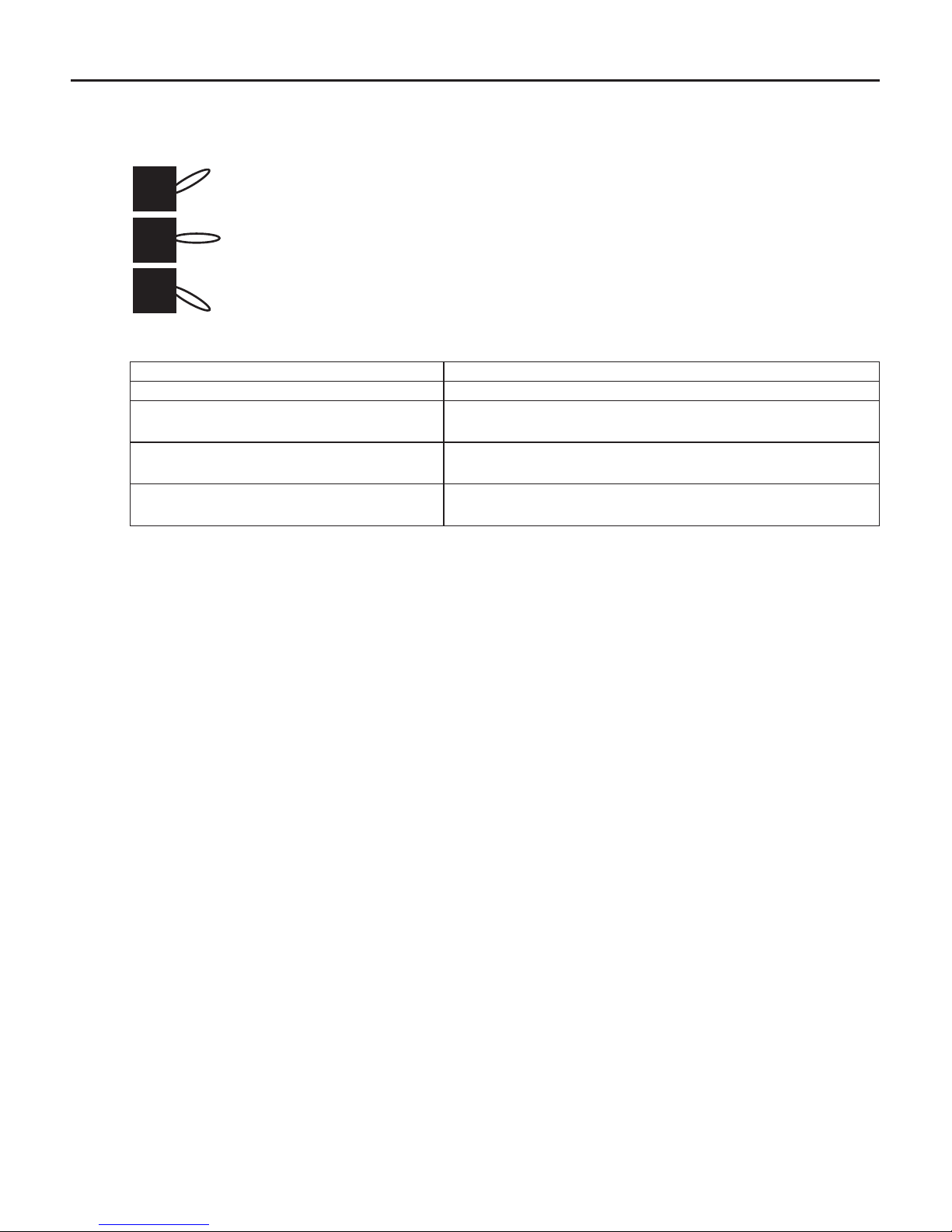
The multi function switch/button is constructed as follows:
run (switch)
stop/reset
clear (button)
The button S1 is assigned with the following functions
Action Function
Run/Stop Program is started
Run/Stop Program is stopped, all variables are reset (reset
warm)
Stop –> Clear and hold (> 3 s) until
ERROR-LED lights
After releasing the switch all retain variables are reset
(reset cold)
Stop –> Clear and hold (>10 s) until
ERROR and RUN-LED light
All variables and the boot project are cleared (reset
origin) after releasing the button.
Since a C6 permits several IEC programs simultaneously (applications) all applications are
started/stopped/cleared with Run/Stop/Clear. The switch operation can be limited by functions
of the library "KEB PLC".
2.10 File system
The le system consists of an internal built-in ash memory (drive C:) and an internal RAM
memory (drive B:). Access is possible via the programming system, KEB ftp or directly by the
IEC control program (library „SysFile“).
From rmware version 3.4.1.3 single les are protected on drives B: and C: by an access
level. The access level is depending on the adjusted password via parameter ud.01.
The actual level is saved when creating/copying a le. The actual access level must be greater
or equal to the le level to delete or rename a le.
When using KebFtp only the user read/write password can be used for compatibility reasons
and appears internally as le level 1. From KebFtp 1.5.0.0 the actual access level is displayed
when selecting a drive and the le level when selecting a le.
2.10.1 Internally Ram-Memory
Drive B: is a temporary memory which is deleted after power on.
• Access is possible only to les in the root directory.
• Long le names to 32 characters are possible.
2.10.2 Internalashmemory
This memory is accessed as drive C:. Any other les (boot projects, projects,
documentation, downloadlists, prescriptions, etc.) can be stored and read here.
Page 19

GB - 19
KEB COMBICONTROL
The following particularities must be observed:
• Access is possible only to les in the root directory.
• Long le names to 32 characters are possible. For COMPACT II up to 60 cha-
racters.
• Reading takes place with high speed.
• Writing occurs at a slow rate, because the ash must be programmed here. New les
are rst created and stored in RAM. When closing the le, the data are stored in the
background to the ash.
• COMPACT Data are not physically deleted. First they are internal marked as
deleted. Thus the available memory capacity decreases. Format and
clear can be activated with parameter FI.07 (can also be started by
the IEC control program with the function "OdWrite").
• COMPACT II Data are automatically deleted in the background and assigned again
as free memory space.Parameter FI.07 has no function here.
Page 20
GB - 20
KEB COMBICONTROL
2.11 Fieldbus interface
Depending on the article number different eldbus modules are integrated via the eldbus
option cards X6D. Fieldbuses PROFIBUS-DP, CAN and INTERBUS are available at the time.
The eldbus modules operate as slave and are accessed via the library "KebPLC“. Furthermore there are nished function blocks for each supported eldbus, which allow process data
allocation and access via the parameterizing channel.
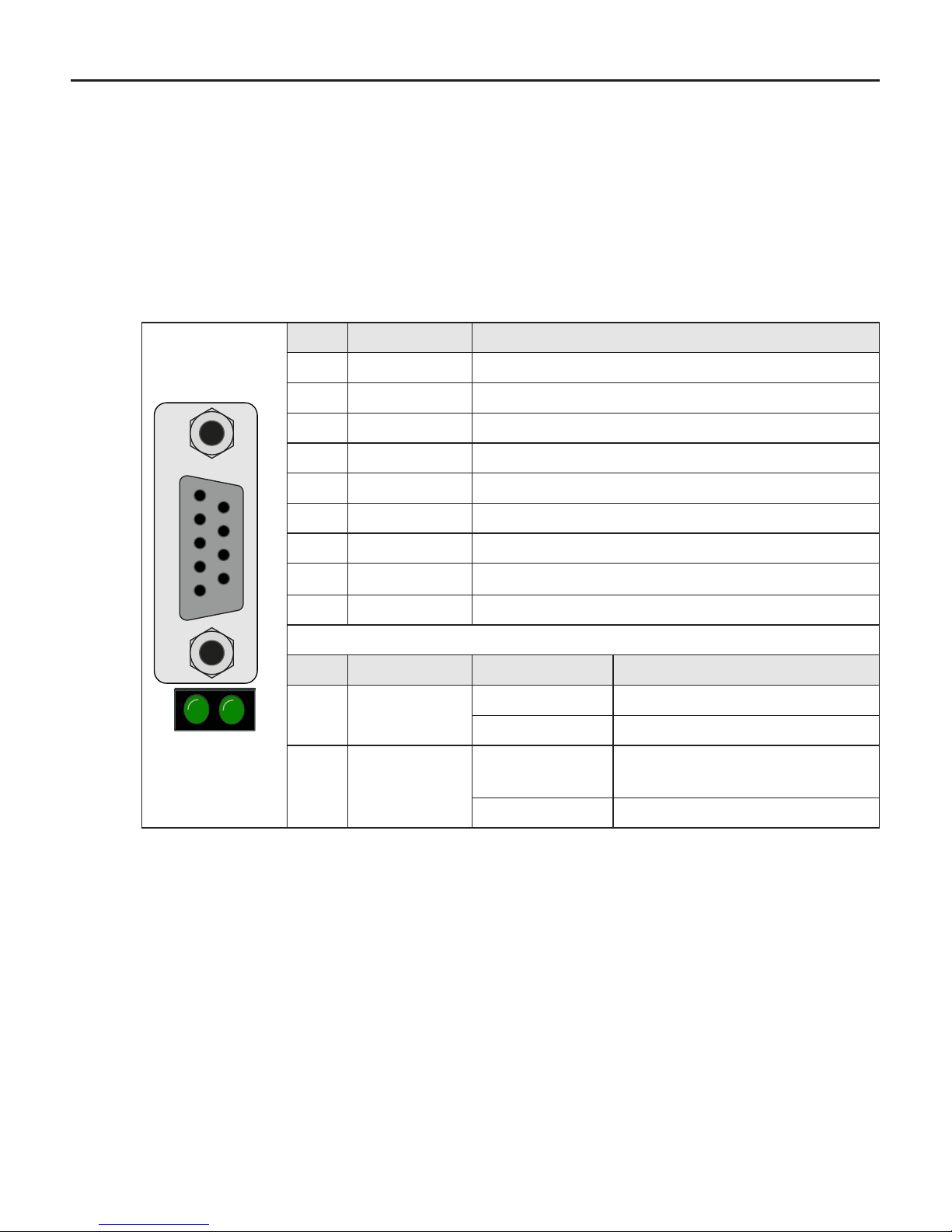
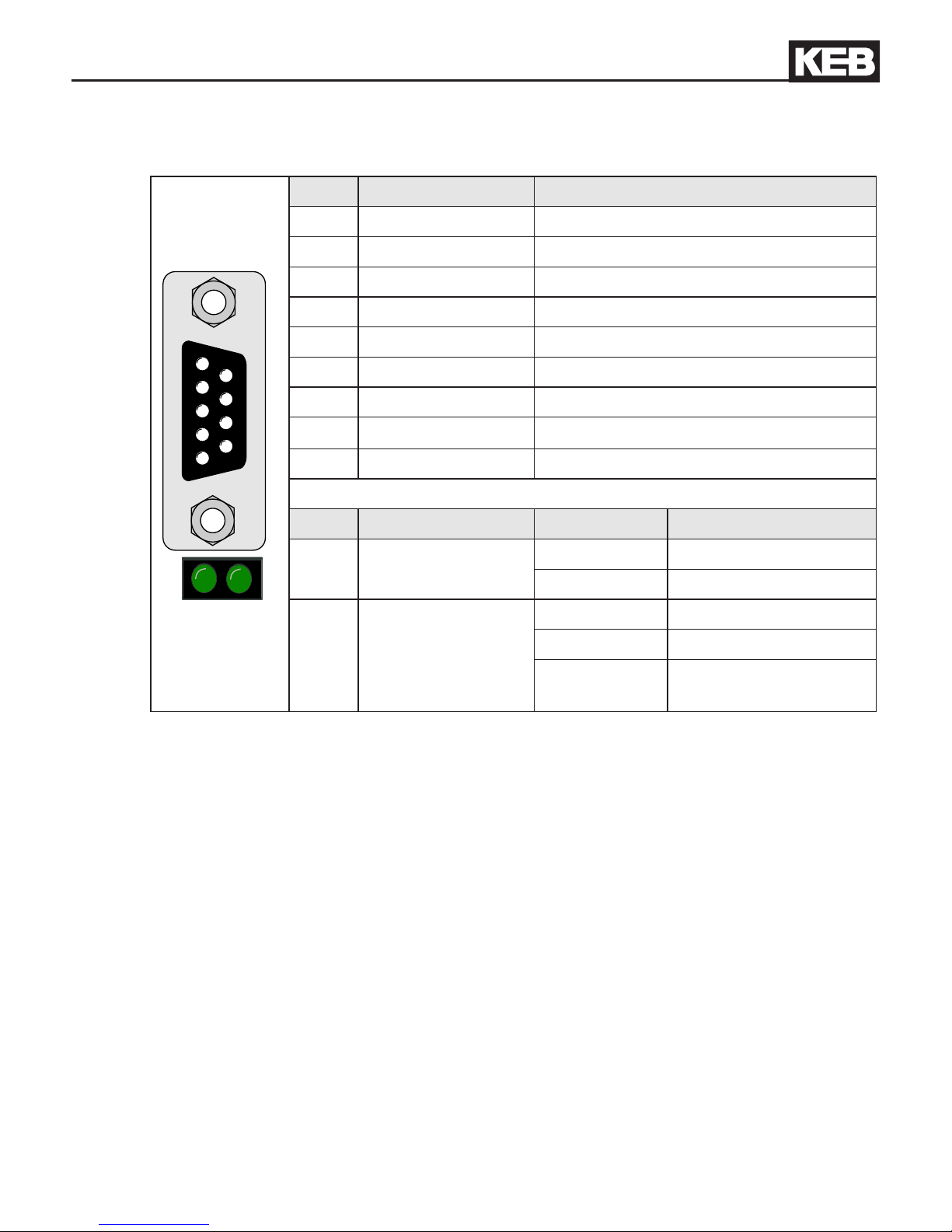
2.11.1 Fieldbus interface PROFIBUS DP
5 4 3 2 1
9 8 7 6
LD6 LD5
PIN Signal Description
1 ---- reserved
2 ---- reserved
3 RxD/TxD-P transmit/receive signal P
4 ---- reserved
5 DGND data reference potential
6 VP supply voltage for terminating resistor
7 ---- reserved
8 RxD/TxD-N transmit/receive signal N
9 ---- reserved
LED Signal Light pattern Meaning
LD5 Ready
on ready for operation
off not ready for operation
LD6 Data
on Data are transmitted by the
PROFIBUS
off no data transmission
The connection is described in the installation instruction (8.021). These can be downloaded
from www.probus.com.
Page 21
GB - 21
KEB COMBICONTROL
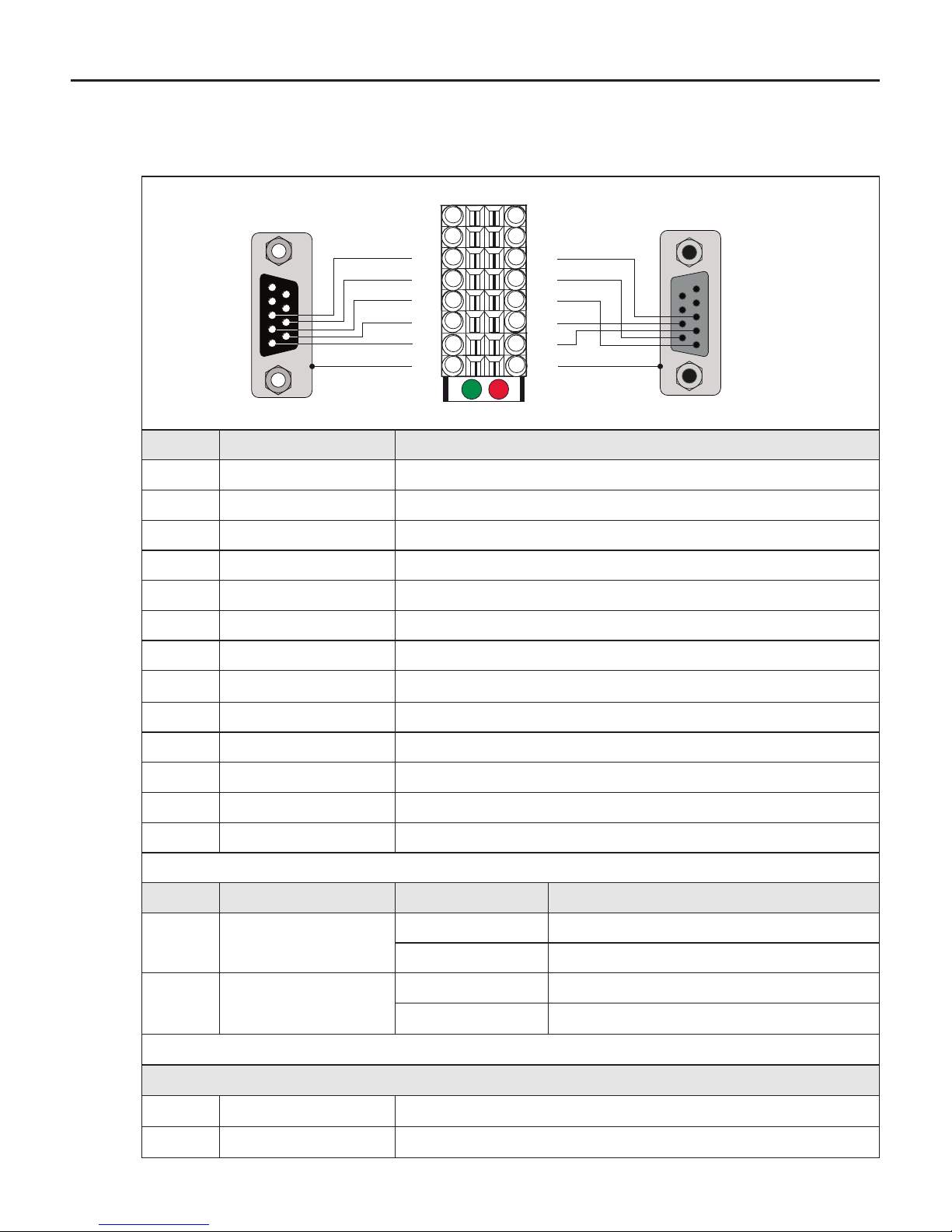
2.11.2 CAN Bus interface
54321
9876
LD6 LD5
PIN Signal Description
1 reserved not connected
2 CAN_L CAN bus signal dominant low
3 CAN_GND not connected
4 reserved not connected
5 CAN_SHLD not connected
6 GND not connected
7 CAN_H CAN bus signal dominant high
8 reserved not connected
9 CAN_V+ not connected
LED Signal Light pattern Meaning
LD5 Ready
on ready for operation
off not ready for operation
LD6 CAN node status
on operational
off Others
blinking pre_Operational, cyclic
with 200 ms OFF
The basic physical characteristics and the connection are described in CiA Draft Standard
102 Version 2.0 and are not explained here.
Page 22
GB - 22
KEB COMBICONTROL
54321
9876
X6D
15
13
11
9
7
5
3
1
16
14
12
10
8
6
4
2
BA
RD
IB_in IB_out
5 4 3 2 1
9 8 7 6
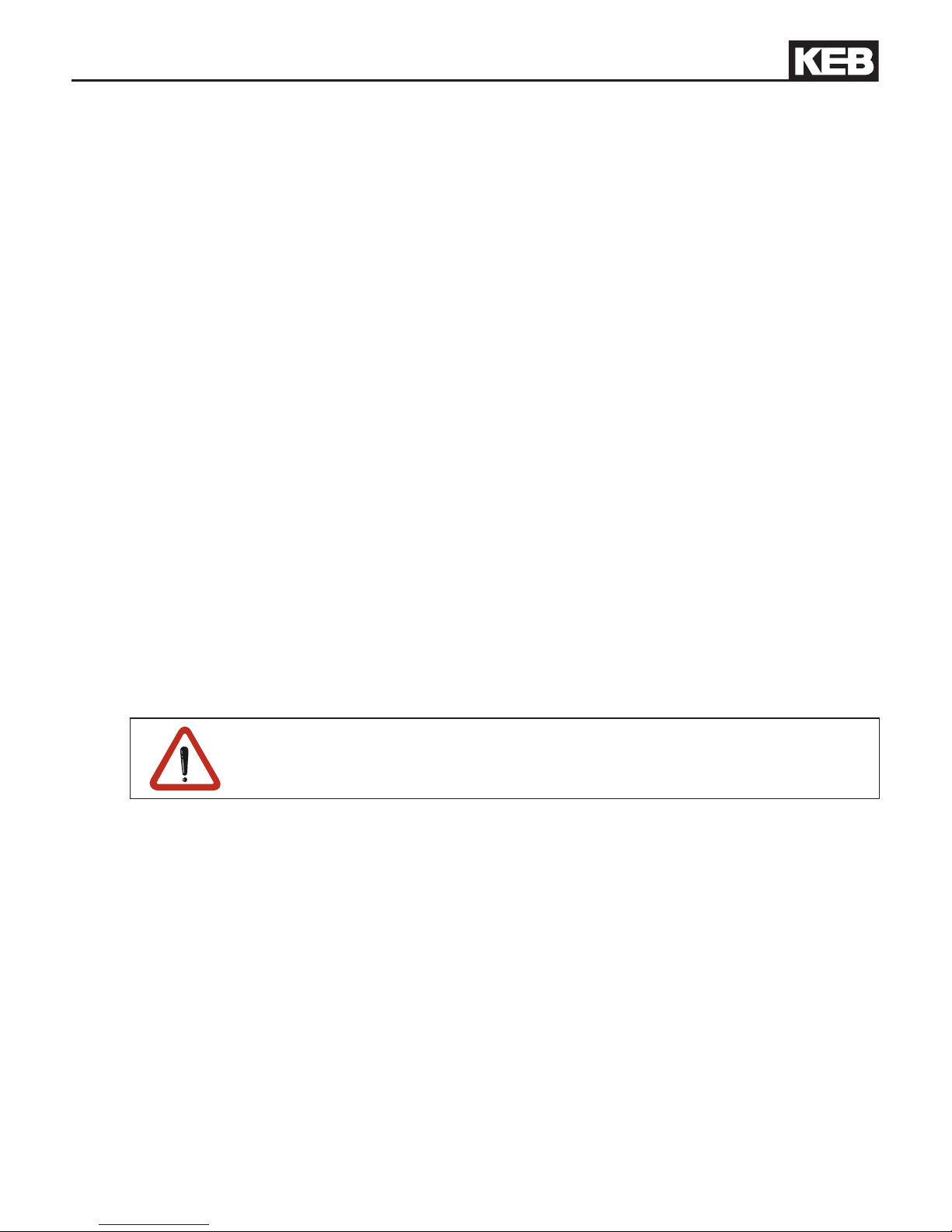
2.11.3 INTERBUS-Interface
PIN Signal Description
1 Shielding Connect-up at connector housing IB_in
2 Shielding2 Connect-up at connector housing IB_out
3 DI2 Data input IB_out
4 DO1 Data input IB_in
5 /DI2 Data input inverted IB_out
6 /DO1 Data input inverted IB_in
7 DO2 Data output IB_out
8 DI1 Data output IB_in
9 /DO2 Data output inverted IB_out
10 /DI1 Data output inverted IB_in
11 GND2 Functional earth
12 GND1 Functional earth
13…16 nc not connected
LED Signal Light pattern Meaning
BA green
on Data transmission active
off Data transmission inactive
RD red
on Interbus output deactivated
off Interbus output activated
Connection at wiring with D-Sub9 cable
IB_in Connector
Interbus input
IB_out Socket
Interbus output (not assigned at the last unit)
Page 23
GB - 23
KEB COMBICONTROL
3. Software
The units of the series C6 are programmed with the programming system KEB COMBIVIS
Studio 6. There are programmable and parameterizing components.
3.1 Programming system
A device description le as well as different libraries are required for the programming of the
C6 compact. These are already installed during the installation of COMBIVIS Studio 6. If
necessary, they can also be installed later. The use of the library components are explained
in available sample projects.
The connection to C6 occurs via the Ethernet interface X6B. IP address and subnet mask
can be preset via the parameterizing system.
The programming system is provided by inserting an unit of category "Controls (PLC)" in the
project. The IEC program can be loaded and started by inserting a task conguration and at
least one task.
3.1.1 Boot projects
Boot projects are stored as le in drive C: and registered in the runtime system. Then they
are automatically loaded and started when switching on. Maximally 4 applications = 4 boot
projects are possible in the C6 compact. Boot projects can be written directly online in the
control or ofine transmit as le.
Ofine: An additional le "bootproject.ini" is required on drive C: in order that the applications
are registered at ofine operation in runtime system. This le is read, evaluated and deleted at
the next power on start. In this le the names of the boot projects are listed (up to 4) in their own
line. The name is the le name of the boot project (e.g. Application) without extension „.app“.
The le name of the boot project must be exactly written as the name of the
application in the project (case sensitivity). COMBIVIS Studio 6 offers this
already at the generation of the ofine boot project le.
3.2 Parameterizing system
The parameterizing system is provided by inserting an unit of category COMBIVIS 6 units
in the project. Serial, if no running IEC program has access to the serial interface X6A, or
the internal parameters of the runtime system are displayed via UDP port 8001. The node
address is set to 0. Parameters of the connected axes can also be displayed depending on
the node address with running IEC program.
Page 24
GB - 24
KEB COMBICONTROL
3.3 Parameter description
The following parameters are available in the runtime system and enable the conguration
and diagnostics of it. Access to the parameters can also be done via the IEC control program
(Library „KebPlc") (OdRead/OdWrite):
3.3.1 Ethernet Parameter
et.00 MAC address Address 0300h
The MAC address (Media Access Control) is formed of 6 byte. Only the lowest 4 bytes are
displayed here „FAxxxxxx“. This address is assigned by the manufacturer and cannot be
changed.
et.01 IP address Address 0301h
The IP address consists of 4 bytes and is the clear identication of one Internet participant.
In case of doubt the network administrator gives the address to be adjusted.
et.04 IP error count Address 0304h
Serves for the diagnosis of the IP protocol stack.
et.05 TCP connections Address 0305h
This parameter displays the number of active TCP/IP connections.
et.06 UDP connections Address 0306h
This parameter displays the number of active UDP connections.
et.08 TCP multicount Address 0308h
This parameter serves only for diagnostic purposes.
et.09
Data port password
Address 0309h
This parameter denes the write protection password for the access via port 8001. If the
password is active rst this password must be entered again for a write access. Error message
"operation not possible" is displayed in case of locked data port write access. Value 0 switches
off the write protection password (only possible if the active password is correct entered).
et.10
Gateway address
Address 030Ah
This parameter determines the IP address of the appropriate gateway. As soon as a connection to IP slave address outside the own network shall be made by the IEC control program,
this address will be used. In case of doubt the gateway address to be adjusted can be ask
for by the network administrator.
Page 25
GB - 25
KEB COMBICONTROL
et.11
Subnet mask
Address 030Bh
The decision whether an IP slave address is outside of the own network is determined with
this mask. The mask presents as follows: 0.0.0.0 the standard masks are used depending
on network classes A, B or C. In case of doubt the subnet mask to be adjusted can be ask
for by the network administrator.
The correct subnet mask must be adjusted for the connection with the programming system!
et.12
data port response delay
Address 030Ch
This parameter adjusts the response delay for the port 8001 in ms. The network utilization
can be reduced by setting of higher values. A value of 0 enables the fastest communication with the control, but a high network utilization is also generated.
et.14
Link state
Address 030Eh
Displays state informations for the Ethernet link.
et.15
Link mode
Address 030Fh
Determines the adjustments of the Ethernet interface. Fixed values or automatic recognition can be adjusted here. The additional clearlock value 32 activates a special behaviour,
which corrects link problems automatically with automatic detection on both sides (control
and switch).
3.3.2 Real-time clock
The internal realtime clock is adjusted and/or read-out with the following parameters:
rc.00
time
Address 0400h
This parameter displays the time in hours and minutes in a 24-hours format. Writing on
this parameter adjusts the time.
rc.01
seconds
Address 0401h
This parameter displays the seconds in a range of 0...59. Writing on this parameter adjusts the seconds.
rc.02
date
Address 0402h
This parameter displays the date in a DD-MM format. Writing on this parameter adjusts
the date.
rc.03
year
Address 0403h
This parameter displays the year in four digits. Writing on this parameter adjusts the year.
Page 26
GB - 26
KEB COMBICONTROL
rc.04 data valid Address 0404h
The realtime clock is running for approx. 30 days after switching off the supply. After this it
must be adjusted again. If this parameter has the value „false“, the date and/or time is not
correct. The clock must be adjusted.
3.3.3 Userdenitionparameter
ud.01 Password Address 0801h
Enter the password for the appropriate user level and le access level. Following values
are possible:
100 CP mode write protection File level 0
200 CP mode read/write File level 1
330 CP mode service File level 2
440 Application mode File level 3
xxx Supervisor File level 7
Ud.02 Features Address 0802h
Display of the actual disconnected special functions (e.g. SoftMotion)
ud.03 IO module Address 0803h
This parameter displays the installed I/O module.
ud.04 eldbusmodule Address 0804h
This parameter displays the installed Fieldbus module.
ud.09 Indirect set pointer Address 0809h
Display and adjustment of the set indicator for indirect parameter access.
3.3.4 Flashlesystem
Fl. 00 max. bytes Address 0900h
Displays the max. bytes in the ash. This is the sum of used, deleted and free bytes.
Fl. 01 max.les Address 0901h
Displays the max. les in the ash.
Fl. 02 used bytes Address 0902h
Displays the actual used bytes in the ash.
Fl. 03 usedles Address 0903h
Displays the actual used les in the ash.
Page 27
GB - 27
KEB COMBICONTROL
Fl. 04 deleted bytes Address 0904h
Displays the cleared bytes in the ash. The ash must be formatted or cleared in order to
make this place available again (not at COMPACT II).
Fl. 05 deletedles Address 0905h
Displays the cleared les in the ash.
Fl. 06 free bytes Address 0906h
Displays the free bytes in the ash.
Fl. 07 ashfunction Address 0907h
Displays the ash status and enables the following functions by writing of a special value:
Formatting = -359074020 clearing = 597981618. Formatting only possible with supervisor
password!
3.3.5 Debugging
Parameters 06xxh are only used for the diagnosis during the production process.
3.3.6 System parameter
sy.01 Software date Address 0001h
This parameter displays the date of the installed rmware.
sy.02 deviceidentier Address 0002h
This parameter displays the software identication number (CFG-ID).
SY.07 baud rate 66019II Address 0007h
The baud rate for the KEB DIN 66019II protocol is adjusted with this parameter. If the serial
interface X6A is used by the IEC control program, this adjustment is no longer valid.
SY.8 response delay 66019II Address 0008h
The response delay for the KEB DIN 66019II protocol is adjusted with this parameter. If the
serial interface X6A of the IEC control program is used, this adjustment is no longer valid.
Page 28
KEB Antriebstechnik Austria GmbH
Ritzstraße 8 • A-4614 Marchtrenk
fon: +43 7243 53586-0 • fax: +43 7243 53586-21
net: www.keb.at • mail: [email protected]
KEB Antriebstechnik
Herenveld 2 • B-9500 Geraadsbergen
fon: +32 5443 7860 • fax: +32 5443 7898
mail: [email protected]
KEB Power Transmission Technology (Shanghai) Co.,Ltd.
No. 435 Qianpu Road, Chedun Town, Songjiang District,
CHN-Shanghai 201611, P.R. China
fon: +86 21 37746688 • fax: +86 21 37746600
net: www.keb.cn • mail: [email protected]
KEB Antriebstechnik Austria GmbH
Organizační složka
K. Weise 1675/5 • CZ-370 04 České Budějovice
fon: +420 387 699 111 • fax: +420 387 699 119
net: www.keb.cz • mail: [email protected]
KEB Antriebstechnik GmbH
Wildbacher Str. 5 • D–08289 Schneeberg
fon: +49 3772 67-0 • fax: +49 3772 67-281
mail: [email protected]
KEB España
C/ Mitjer, Nave 8 - Pol. Ind. LA MASIA
E-08798 Sant Cugat Sesgarrigues (Barcelona)
fon: +34 93 897 0268 • fax: +34 93 899 2035
mail: [email protected]
Société Française KEB
Z.I. de la Croix St. Nicolas • 14, rue Gustave Eiffel
F-94510 LA QUEUE EN BRIE
fon: +33 1 49620101 • fax: +33 1 45767495
net: www.keb.fr • mail: [email protected]
KEB (UK) Ltd.
6 Chieftain Buisiness Park, Morris Close
Park Farm, Wellingborough GB-Northants, NN8 6 XF
fon: +44 1933 402220 • fax: +44 1933 400724
net: www.keb-uk.co.uk • mail: [email protected]
KEB Italia S.r.l.
Via Newton, 2 • I-20019 Settimo Milanese (Milano)
fon: +39 02 3353531 • fax: +39 02 33500790
net: www.keb.it • mail: [email protected]
KEB Japan Ltd.
15–16, 2–Chome, Takanawa Minato-ku
J–Tokyo 108-0074
fon: +81 33 445-8515 • fax: +81 33 445-8215
mail: [email protected]
KEB Korea Seoul
Room 1709, 415 Missy 2000
725 Su Seo Dong, Gang Nam Gu
ROK-135-757 Seoul/South Korea
fon: +82 2 6253 6771 • fax: +82 2 6253 6770
mail: [email protected]
KEB RUS Ltd.
Lesnaya Str. House 30, Dzerzhinsky (MO)
RUS-140091 Moscow region
fon: +7 495 550 8367 • fax: +7 495 632 0217
net: www.keb.ru • mail: [email protected]
KEB Sverige
Box 265 (Bergavägen 19)
S-43093 Hälsö
fon: +46 31 961520 • fax: +46 31 961124
mail: [email protected]
KEB America, Inc.
5100 Valley Industrial Blvd. South
USA-Shakopee, MN 55379
fon: +1 952 224-1400 • fax: +1 952 224-1499
net: www.kebamerica.com • mail: [email protected]
© KEB
Mat.No. 00C6NEB-BA00
Rev. 1D
Date 02/2013
More and newest addresses at http://www.keb.de
Karl E. Brinkmann GmbH
Försterweg 36-38 • D-32683 Barntrup
fon: +49 5263 401-0 • fax: +49 5263 401-116
net: www.keb.de • mail: [email protected]
KEB worldwide…
 Loading...