

Keating Of Chicago SERIES 2006 User Manual

SERIES 2006 FRYER MANUAL
INSTANT RECOVERY
®
ELECTRIC FRYER
READ AND SAVE THIS MANUAL FOR FUTURE REFERENCE
Record the Model No. and Serial of this Instant Recovery
®
Electric Fryer in the space provided below.
Serial No. __________________________
Model No. __________________________
Keep these numbers for future reference
IMPORT ANT: Keep a copy of your bill of sale. The date on the bill establishes the warranty period should
service be required. If service is performed, it is in your interest to obtain and keep all receipts. Keating
commercial fryers are intended for other than household use.
CONTENTS:
INTRODUCTION
General . . . . . . . . . . . . . . . . . . . . . . . . . . . . . . . . . . . . . . . . . 1
Standard Features. . . . . . . . . . . . . . . . . . . . . . . . . . . . . . . . . 1
Model Variations . . . . . . . . . . . . . . . . . . . . . . . . . . . . . . . . . . 1
Safety Precautions . . . . . . . . . . . . . . . . . . . . . . . . . . . . . . . . 1
INSTALLATION
Damage During Shipment . . . . . . . . . . . . . . . . . . . . . . . . . . . 2
Installation . . . . . . . . . . . . . . . . . . . . . . . . . . . . . . . . . . . . . . . 2
Drop-In Installation . . . . . . . . . . . . . . . . . . . . . . . . . . . . . . . . 2
Positioning. . . . . . . . . . . . . . . . . . . . . . . . . . . . . . . . . . . . . . . 3
Leveling . . . . . . . . . . . . . . . . . . . . . . . . . . . . . . . . . . . . . . . . . 3
Restraining Devices. . . . . . . . . . . . . . . . . . . . . . . . . . . . . . . . 3
Electrical Connection . . . . . . . . . . . . . . . . . . . . . . . . . . . . . . 3
OPERATING THE FRYER
Filling . . . . . . . . . . . . . . . . . . . . . . . . . . . . . . . . . . . . . . . . . . . 4
Melting. . . . . . . . . . . . . . . . . . . . . . . . . . . . . . . . . . . . . . . . . . 4
Cooking . . . . . . . . . . . . . . . . . . . . . . . . . . . . . . . . . . . . . . . 4-5
Shutdown . . . . . . . . . . . . . . . . . . . . . . . . . . . . . . . . . . . . . . . 5
Draining . . . . . . . . . . . . . . . . . . . . . . . . . . . . . . . . . . . . . . . 5-6
Cleaning and Boil-Out . . . . . . . . . . . . . . . . . . . . . . . . . . . . 6-7
Electronic Timers. . . . . . . . . . . . . . . . . . . . . . . . . . . . . . . . . . 7
SERVICE DIAGNOSIS
General . . . . . . . . . . . . . . . . . . . . . . . . . . . . . . . . . . . . . . . . . 9
Trouble Shooting Charts . . . . . . . . . . . . . . . . . . . . . . . . . 9-10
PARTS LIST
Ordering Parts . . . . . . . . . . . . . . . . . . . . . . . . . . . . . . . . . . . 11
Warning and Operating Plates . . . . . . . . . . . . . . . . . . . . . . 11
Electric Fryer Parts List. . . . . . . . . . . . . . . . . . . . . . . . . . . . 12
Electric Fryer Assembly. . . . . . . . . . . . . . . . . . . . . . . . . . . . 12
BB Control Panel Parts List . . . . . . . . . . . . . . . . . . . . . . . . 13
TS Control Panel Parts List . . . . . . . . . . . . . . . . . . . . . . 14-15
Basket-Lift Housing and Roller Guide & Parts List . . . . 16-17
WIRING DIAGRAMS
Single Basket Lift Power Supply Box . . . . . . . . . . . . . . . . . 18
10×11, 14, 18, 20 BB Wiring Diagrams . . . . . . . . . . . . . 19-23
TS Wiring Diagrams . . . . . . . . . . . . . . . . . . . . . . . . . . . . 24-30
FRYER SPECIFICATIONS
BB Models. . . . . . . . . . . . . . . . . . . . . . . . . . . . . . . . . . . . . . 31
TS Models . . . . . . . . . . . . . . . . . . . . . . . . . . . . . . . . . . . . . . 25
Warranty . . . . . . . . . . . . . . . . . . . . . . . . . . . . . . . . . . . . . . . 26
MAINTENANCE
Warranty Repairs. . . . . . . . . . . . . . . . . . . . . . . . . . . . . . . . . . 8
Preventive Maintenance . . . . . . . . . . . . . . . . . . . . . . . . . . . . 8
Oil Breakdown. . . . . . . . . . . . . . . . . . . . . . . . . . . . . . . . . . . . 8
Limited Calibration . . . . . . . . . . . . . . . . . . . . . . . . . . . . . . . . 8
Thermostat Bulb Positioning. . . . . . . . . . . . . . . . . . . . . . . . . 8
This Owner’s Guide provides specific operating instructions for your model. Use the Instant Recovery®Fryer only
as instructed in this Service Guide.
Si desea obtener una copia en español de este Manual de el Usuario, sirvase escribir a la dirección que se
incluye a continuación.
Versión en español
1-800-KEATING
www.keatingofchicago.com
Electric Fryer 2006 09/07
POST THIS LABEL IN A
PROMINENT LOCATION ON
YOUR UNIT.
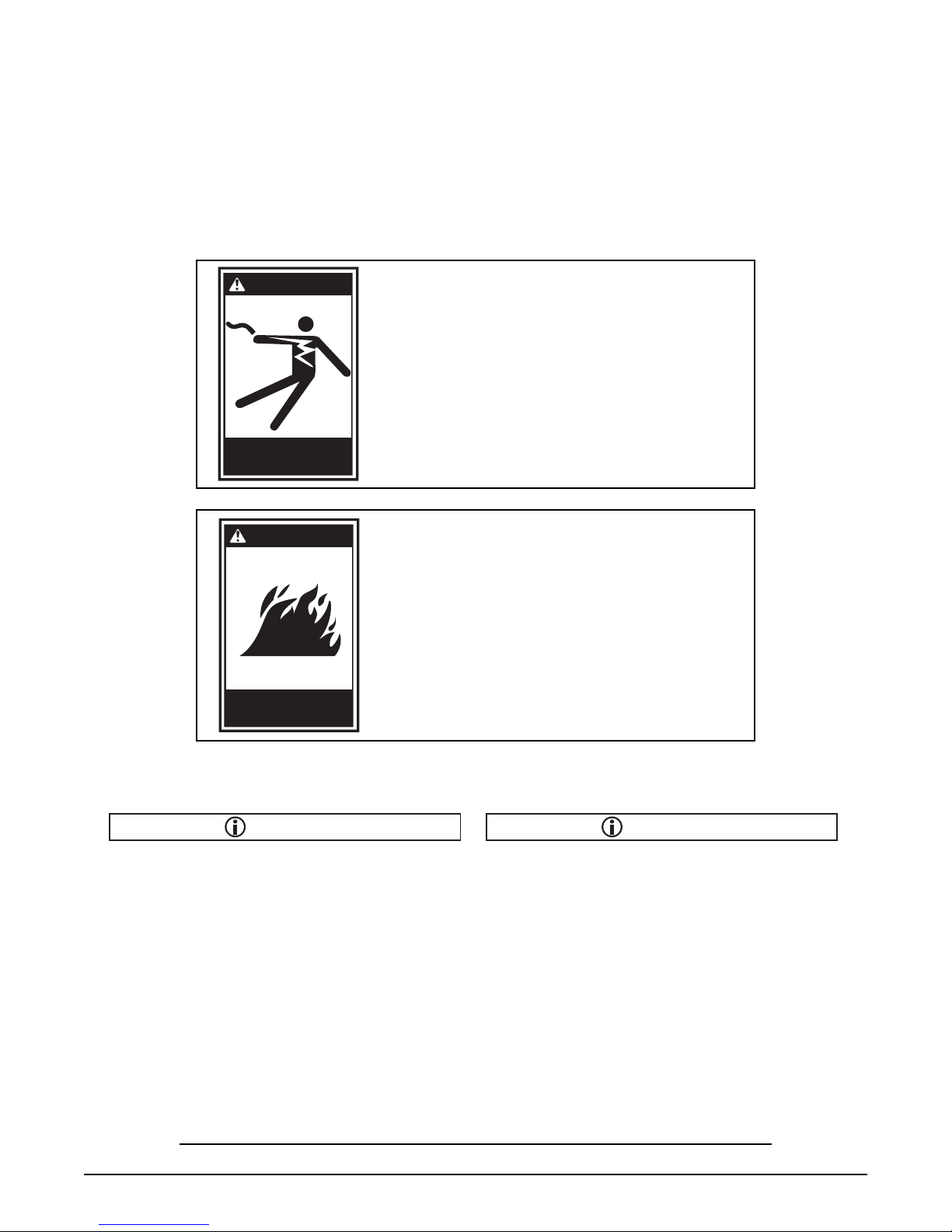
WARNING
IMPROPER INSTALLATION, ADJUSTMENT,
ALTERATION, SERVICE OR MAINTENANCE CAN
CAUSE PROPERTY DAMAGE, INJURY OR DEATH.
READ THE INSTALLATION, OPERATING AND
MAINTENANCE INSTRUCTIONS THOROUGHLY
BEFORE INSTALLING OR SERVICING THIS
Improper installation
can cause damage,
injury or death.
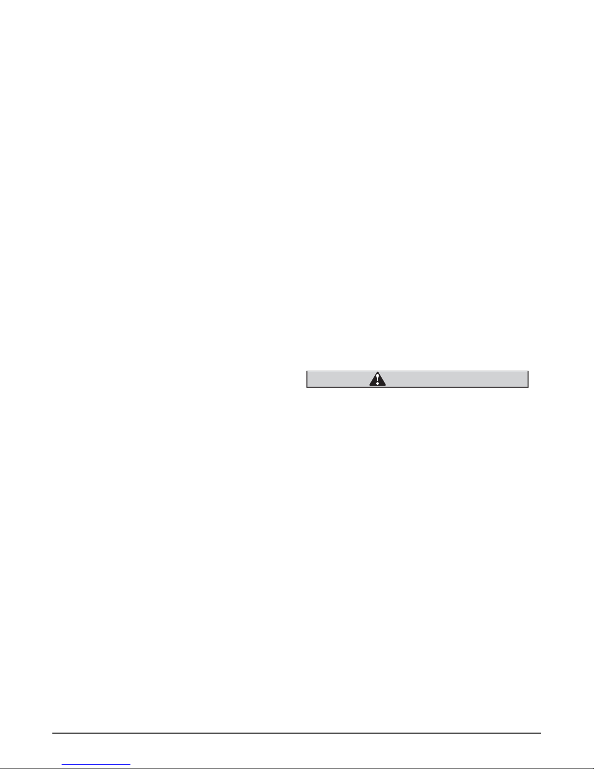
WARNING
EQUIPMENT.
FOR YOUR SAFETY, DO NOT STORE GASOLINE
OR ANY OTHER FLAMMABLE VAPORS OR
LIQUIDS IN THE VICINITY OF THIS OR ANY
OTHER APPLIANCE.
Do not store flammable
liquids near this or any
other appliance.
This operating, installation, and service manual should
be given to the user. The operator of the fryer should
be familiar with the functions and operation of the fryer.
This manual must be kept in a prominent, easily
reachable location near the fryer.
NOTICENOTICE
Keating of Chicago, Inc. (manufacturer) reserves the
right to change specifications at any time.
*As continuous product improvement occurs, specifications may be changed without notice.
i
INTRODUCTION
GENERAL
Keating Instant Recovery®Electric Fryers are designed
to give maximum production efficiency, delivering high
quality food products. The following design features are
incorporated in Keating Instant Recovery
Fryers.
STANDARD FEATURES
Highly polished stainless steel fryer vessel
Highly polished stainless steel front
Highly polished stainless steel elements
Highly polished stainless steel thermostat bulb
Highly polished stainless steel Hi-Limit sensor
True Cold Zone for proper sedimentation
Grid screen over elements
Melt cycle
1” full port front drain valve on 10x11 and 14;
1-1/4” for 18 and larger
High temperature limit control with manual reset
Patented accurate temperature control system ±7°F
Ideal 35” working height
One pair of split baskets or one full-size basket
Circuit breaker protection for 208-240V 10×11 to
34×24 Models.
STANDARD ACCESSORIES
Keating Klenzer Sample
Keating Sea Powder Sample
Drain clean out rod
STANDARD FRYERS
Sizes: 10×11 to 34×24
Oil capacity 30 to 210 pounds
NSF, ETL and ETLS listed.
MODEL VARIATIONS
BB Model: BB Model Fryers feature Power On
indicating light, a melt cycle and an electric stainless
steel thermostat. The 14BB model can cook up to 72
lbs. of frozen fries or 75 lbs. of chicken per hour.
®
Electric
TS Model: TS Model Fryers have the highest input of
all Keating fryers. The TS Model features a melt cycle,
and electric stainless steel thermostat, two electronic
timers and three indicating lights which display the
status of the fryer’s operation. The 14TS Model can
cook up to 90 lbs. of frozen fries or 75 lbs. of chicken
per hour.
TS Basket-Lift Model: TS Basket-Lift Model Fryers
come with all the same features as the TS Model. The
Basket-Lift mechanism lowers the baskets of food into
the oil when the timer button is pressed and raises the
baskets when the cooking cycle is complete. Split
baskets are used for all models.
CM Model: BB and TS Counter Model Fryers are
equipped with all of the same features as the BB and
TS Models respectively, but take up less than three
square feet of counter space. The 10x11CM Model can
cook up to 36 lbs. of frozen fries per hour and the
14CM Model can cook up to 72 lbs. per hour.
CPU Model: CPU Model Fryers have the same input
as the TS Models, and features an over max
temperature light. A programmable computer replaces
the two timers and thermostat.
SAFETY PRECAUTIONS
WARNING
THIS SYMBOL WARNS YOU THAT SERIOUS BURNS
OR OTHER INJURIES MAY RESULT IF SAFETY
INSTRUCTIONS ARE NOT FOLLOWED.
This service manual should be retained in a safe place
for future reference. The installation of your new fryer
must conform to current codes, with the current National
Electrical Codes and regulations as applicable.
Your ventilation hood, when installed, must conform to
the current standards.
You must maintain this appliance free and clear from
combustibles.
Adequate clearance for servicing and proper operation
must be maintained. Your fryer is designed to be
serviced from the front.
Keating commercial fryers are intended for other than
household use.
ALWAYS instruct new employees on proper fryer operation.
A fryer should be operated ONLY by properly trained
personnel.
ALWAYS turn fryer off each night.
ALWAYS turn fryer off at customer power panel before
servicing.
NEVER leave a fryer unattended during operation.
NEVER move a fryer when full of hot oil.
NEVER introduce objects or liquids into fryer, while
operational, which are not designed or made for
cooking.
THIS FRYER MAY NOT BE ALTERED, MODIFIED OR
CHANGED IN ANY WAY.
1
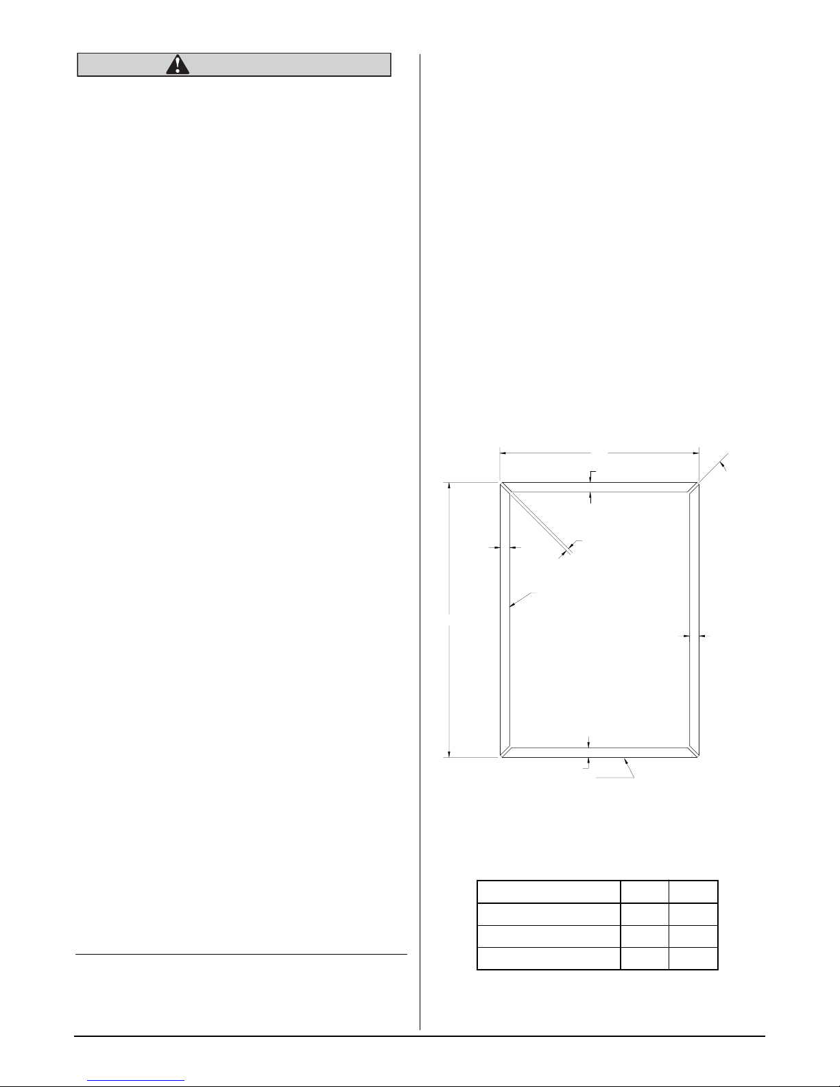
5/8"
5/8"
5/8"
CUT LINE
"A"
"B"
BEND UP 90° ON ALL SIDES
TO FINAL OPENING SIZE ("A" X "B"),
THEN CLOSE CORNERS BY WELDING
AN INSERT PIECE (OR OTHER SUITABLE
METHODS) FOR A LEAK FREE FIT.
45°
TYP.
DETERMINED BY
CUTTING TOOL
USED
5/8"
1/8"
WARNING
IMPROPER INSTALLATION, SERVICE OR
MAINTENANCE CAN CAUSE PROPERTY
DAMAGE, INJURY OR DEATH. READ THESE
INSTALLATION, OPERATING AND MAINTENANCE
INSTRUCTIONS THOROUGHLY BEFORE
INSTALLING OR SERVICING THIS EQUIPMENT.
INSTALLATION
DROP-IN FRYER INSTALLATION NOTES
1. All drop-in fryers must be 16” from any open flame.
2. Fryers must be located no more than 5” from
counter top front.
3. Cabinet must be reinforced to support full weight of
fryer in use (fryer, oil, food).
4. Fryers must be properly ventilated and located
under an exhaust hood.
This fryer MUST be installed, inspected, calibrated and
serviced by qualified and/or certified and/or licensed
service personnel - you may void your Keating
warranty if installation is not completed per local,
national and Keating specifications. Contact your
dealer for assistance.
DAMAGE DURING
SHIPMENT
The fryer has been assembled, tested and inspected at
the factory. Upon arrival, the complete fryer should be
checked for any damage that may have occurred
during shipment.
The carrier is responsible for all damage in transit
whether visible or concealed. Do not pay for the freight
bill until the fryer has been thoroughly checked for
damage. If concealed damage is found later, contact
the carrier immediately to file a claim.
What to do if equipment arrives damaged:
VISIBLE LOSS OR DAMAGE – Be certain to note
this on the freight or express receipt and have it
signed by the delivery person.
DROPPING THE FRYER INTO THE COUNTER
TOP
It is only necessary to place the fryer in such a position
that the front edge overlaps the front raised edge of the
opening.
Push the fryer forward as far as it will go holding the
fryer on approximately a 15° angle, and then drop the
rear of the fryer into its proper position lowering it down
gently so you do not deform the table or equipment
stand.
FILE CLAIM FOR DAMAGES IMMEDIATELY –
Regardless of extent of damage.
CONCEALED LOSS OR DAMAGE – If damage is
noticed when equipment is unpacked, notify the
freight company immediately, and file a “concealed
damage claim”. This MUST be done immediately. Be
sure to retain the shipping container for inspection.
Keating does not assume responsibility for Loss OR
Damage incurred in transit.
Installation must conform with local codes or, in
INSTALLATION
absence of local codes, with the current National
Electrical Codes and regulations as applicable.
NOTE: For safety purposes, all Hi-Limit controls are
manually reset. Always check the Hi-Limit reset button
before attempting to use the fryer. It is possible that the
Hi-Limit button may have been accidentally activated
on a new fryer while in transit.
Figure 2-1
“A” “B”
10×11DI ELECTRIC 13” 211/2”
14DI ELECTRIC 16” 231/2”
18DI ELECTRIC 20” 273/4”
2

POSITIONING
The fryer must be placed under an exhaust hood with
a fire retardant system. Your ventilation hood, when
installed, must conform to the current standards. ALL
connections and placement must comply with current
local and national codes. It is the responsibility of the
owner and local installer to comply with these
regulations when installing the fryer.
Counter model and floor model fryers must be
restrained to prevent tipping when installed in order
to avoid splashing, spilling, etc. of hot liquid. The
restraining method may be a manner of installation or
by separate means.
LEVELING
The fryer will operate at its highest efficiency when
properly leveled. Place a level on fryer vessel from side
to side. For fryers on legs, the bottom foot of the leg is
adjustable. Looking from the bottom of the foot, turn
clockwise to decrease height or counter clockwise to
increase height until level. For fryers on casters, the
casters are adjustable by loosening the jam nut and
turning the caster in or out. When the desired level is
reached, tighten the jam nut. Adjustments of more than
3
/4” are not recommended on any caster. The same
procedure should be followed to level the fryer from
front to back.
Figure 2-2
RESTRAINING DEVICES
On fryer installations with casters, casters and jam nuts
must be completely tightened. Adequate means must
also be provided to limit the movement of the
appliance.
ELECTRICAL
CONNECTION
The Keating Instant Recovery®Electric fryer is
equipped with a three wire terminal block for customer
connections. The terminal block is located behind the
fryer door on the right side behind a panel (held in
place by two screws). Compare the fryer terminal
connections to the appropriate wiring diagram for the
fryer (see pages 17 thru 23) to see if the fryer is
connected three phase or single phase. All wires/cords,
plugs, receptacles and circuit breakers must be sized
adequately for the full load rating of the fryer as
specified by local codes, or in the absence of local
codes, by the current National and Canadian Electrical
Codes as applicable.
The Keating Electric Fryer is also equipped with a
grounding lug next to the terminal block. For proper
grounding procedures, see local codes or, in the
absence of local codes, by the current National and
Canadian Electrical Codes as applicable.
NOTE: A copy of your wiring diagram is shipped with
your equipment.
LEVEL
LEG
CASTER
NOTE: For fryers rated at 208-240 volts, the
amperage ratings marked on the nameplates of the
fryers are listed at 240 volts as required by ETL. If your
fryer is to be fed by a 208 or 220 volt system, consult
the Keating Fryer Specifications on pages 24 and 25 to
determine the full load rating of the fryer.
NOTE: Fryers with Safe & Easy®Filters (model
BBSE or TSSE) or Central Filters will have separate
120 volt control circuit connections.
NOTE: A copy of your wiring diagram is located on
the inside of the door.
NOTE: A hole has been punched in the rear of the
fryer cabinet for a cord or conduit exit. If a cord is used,
the National Electrical Code, ETL standards and most
local codes require a bushing or strain relief (not
provided by Keating) to protect the cord.
CALIBRATION
For Calibration refer to page 8 - Calibration.
3
OPERATING
FILLING
NOTE: Before filling the fryer make certain the fryer
vessel is sanitized, dry and the drain valve is
completely closed. Refer to figures 3-4, 3-5 on page 6
for location of drain valve.
WARNING
BE SURE THE HEATING ELEMENTS ARE
COMPLETELY COVERED WITH OIL BEFORE
SWITCHING THE FRYER ON. IF OIL LEVEL DROPS
BELOW TOP OF HEATING ELEMENTS, SEVERE
DAMAGE TO FRYER AND INJURY TO OPERATOR
MAY RESULT.
WARNING
MELTING
The Keating Melt Cycle safely melts solid shortening in
the fryer vessel without scorching.
WARNING
BEFORE APPLYING POWER TO THE FRYER,
MAKE SURE THE ELECTRIC CONNECTIONS ARE
SECURE AND THE FRYER HAS BEEN PROPERLY
FILLED WITH OIL.
A. BB, TS and Basket-Lift Models
1. Set the thermostat to the desired temperature.
2. If using solid shortening, set Melt-Fry switch to the
“MELT” position. Stay in the “MELT” cycle until the
shortening has melted completely and is at the
“Max Level” line before switching to the “FRY”
position for cooking.
B. CPU Models
*See separate computer instructions or call
1-800-KEATING.
WATER IN ANY FORM AND HOT OIL DON’T MIX!!!
CAUTION
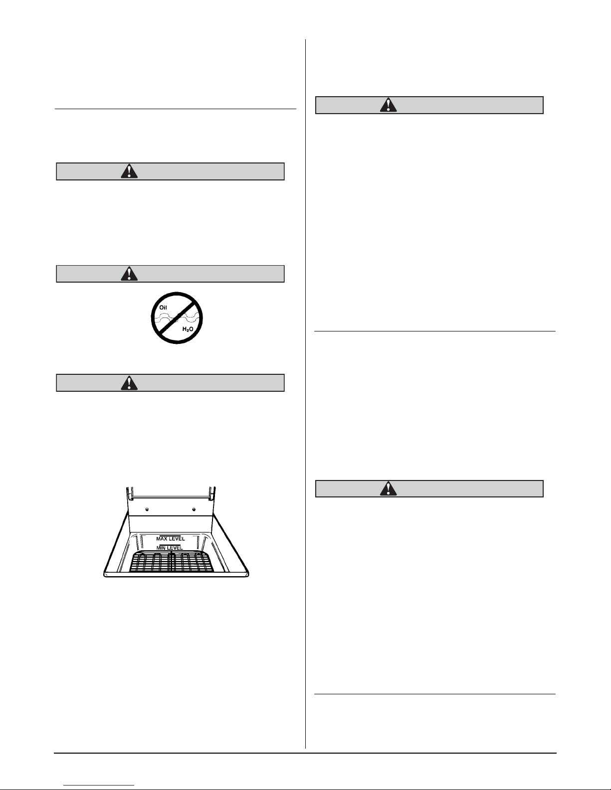
Oil expands when heated. The “Max Level” line has
been provided to ensure optimum cooking while
ensuring the safety of the operator. Do not overfill the
fryer vessel.
Figure 3-1
Fill Level Line
BB & TS, CPU and Basket-Lift Models
1. Fill the fryer vessel with oil up to the “Max Level”
line.
2. If using solid shortening, remove screen and firmly
pack solid shortening between the heating
elements. Proceed to Melting section for
instructions on use of the melt cycle.
NOTE: During the “MELT” cycle, the elements are on
for approximately 5-7 seconds and off for
approximately 50 seconds.
COOKING
Keating Instant Recovery®Electric Fryers are designed
to provide maximum production efficiency and deliver
high quality food products. Low-temperature cooking,
highly polished stainless steel and a true COLD ZONE
mean extended oil life. Follow cooking procedures
below for your model.
WARNING
OPERATION OF THIS FRYER SHOULD BE
LIMITED TO PERSONNEL WHO HAVE BEEN
THOROUGHLY TRAINED IN OPERATING
PROCEDURES.
USE ONLY KEATING APPROVED BASKETS IN
YOUR FRYER. NEVER OVERFILL FRY BASKETS. DO
NOT BANG BASKETS ON BASKET HANGERS OR
FRYER VESSEL.
CARE SHOULD BE TAKEN WHEN LOWERING
BASKETS INTO FRYER TO PREVENT SPLASHING
HOT OIL FROM FRYER VESSEL.
NEVER LIFT BASKETS DIRECTLY OUT OF THE
FRYER VESSEL WITHOUT DRAINING AS SEVERE
INJURY MAY RESULT.
NOTE: For safety purposes, all Hi-Limit controls are
manually reset. Always check the Hi-Limit reset button
before attempting to use the fryer. If the Hi-Limit has
tripped, the fryer will not operate.
4

NOTE: For a fryer with a Central or Safe & Easy
Filter, always check the rear drain operating handle
before attempting to use the fryer. A safety switch
prevents the fryer from operating if the handle is not
pushed in completely and locked into place.
A. BB Models
1. Fill fryer as described on page 4 - Filling.
2. Set Power switch to the “ON” position. “POWER
ON” light will be illuminated.
3. Set the Melt-Fry switch to “FRY.”
4. Set thermostat to the desired frying temperature
(between 325°F and 335°F).
5. When the oil reaches the desired frying
temperature, lower filled basket(s) slowly into the
hot oil.
6. When cooking cycle is complete, carefully lift
basket(s) out of oil. Place them on basket hanger
(on splashback of fryer) to allow draining of excess
oil.
6. Fill basket(s) to proper level and place on upper bar
®
of lift rod(s).
7. Set timer(s) to desired cooking time. For
programming timers see page 7.
8. Push “T1,” “T2” or “T3” buttons on timer(s).
Basket(s) will automatically lower into fryer vessel.
9. When cooking cycle is complete, an audible alarm
will sound and the basket(s) will raise
automatically. Allow oil to drain before removing
baskets.
D. CPU Model
* See separate computer instructions or call
1-800-KEATING
SHUTDOWN
A. BB, TS and Basket-Lift Models
1. Turn fryer Power switch to “OFF” position.
B. CPU Model
B. TS Model
1. Fill fryer as described on page 4 - Filling.
2. Set Power switch to the “ON” position. “POWER
ON” light will be illuminated.
3. Set the Melt-Fry switch to “FRY.”
4. Set thermostat to the desired frying temperature
(between 325°F and 335°F).
5. When the oil reaches the desired frying
temperature, the “READY TO COOK” light will
illuminate.
6. Lower filled basket(s) slowly into the hot oil.
7. Set timer for left or right side basket, whichever is
being lowered into oil. For programming
instructions, see page 7.
8. When timer sounds, lift basket out of oil. Place on
basket hanger (on splashback of fryer) to allow
draining of excess oil.
C. Basket-Lift Models
1. Fill fryer as described on page 4 - Filling.
1. Set Main Power On/Off switch to the “OFF” position.
DRAINING
WARNING
ALWAYS SHUT THE FRYER OFF COMPLETELY
BEFORE DRAINING. THE FRYER SHOULD BE
DRAINED ONLY UNDER THE SUPERVISION OF
PROPERLY TRAINED PERSONNEL. A DRAIN PIPE
AND COVERED CONTAINER SUITABLE FOR USE
WITH HOT OIL SHOULD BE USED TO ENSURE THE
SAFETY OF THE OPERATOR.
1. Operator should be outfitted with proper attire
including:
– Oil and heat resistant gloves
– Oil and heat resistant apron
– Safety goggles
– Oil and heat resistant footwear
Figure 3-2
Operator in safety gear
2. Set Power switch to the “ON” position. “POWER
ON” light will be illuminated.
3. Set the Melt-Fry switch to “FRY.”
4. Set thermostat to the desired frying temperature
(between 325°F and 335°F).
5. When the oil reaches the desired frying
temperature, the “READY TO COOK” light will
illuminate.
2. Turn off the fryer and open the door.
5
3. For front drain fryers, put approved container under
CAUTION
drain valve. For fryers with a central filter, slide filter
drawer in completely.
4. For front drain fryers, slowly turn handle forward to
avoid splashing. The drain valve will be completely
open after 1/4 turn.
5. For units with rear drain valves, slowly pull drain valve
operating handle straight out (unhook from metal latch
first). See Safe & Easy operator’s manual for
instructions on how to filter.
Figure 3-3
Front drain valve
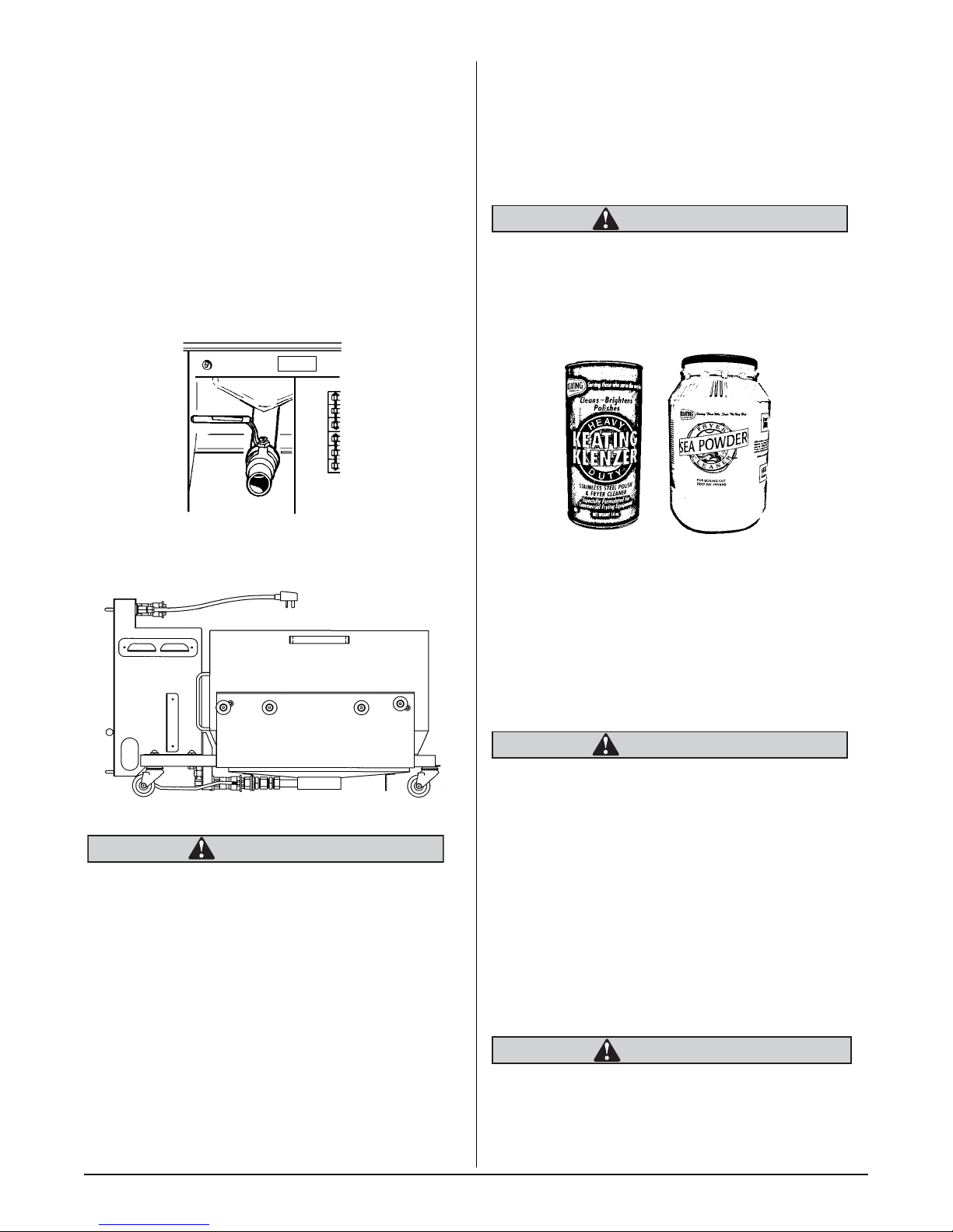
Sea Powder and Keating Klenzer to keep your fryer in
top condition. Keating Sea Powder dissolves any
grease build up—even carbonized grease in fryer
vessels—one of the leading causes of premature oil
breakdown. And once your fryer vessel is clean, use
Keating Klenzer, the finest dry stainless steel polish
available, to restore your Keating Instant Recovery
Electric fryers’ exterior to its original luster.
CAUTION
To avoid damaging the fryer, do not power wash,
spray or hose it down while cleaning.
Figure 3-5
Keating Klenzer and Sea Powder
®
Figure 3-4
Safe & Easy Filter
SIDE VIEW
WARNING
UNDER NO CIRCUMSTANCES SHOULD YOU
PERMIT HOT OIL TO COME IN CONTACT WITH
WATER OR ICE. ALL DRAINING SHOULD BE DONE
UNDER THE SUPERVISION OF PROPERLY
TRAINED PERSONNEL. A DRAIN PIPE AND
COVERED CONTAINER SUITABLE FOR USE WITH
HOT OIL SHOULD BE USED WHENEVER A FRYER
IS DRAINED. ALWAYS DRAIN OIL INTO A
COVERED RECEPTACLE APPROVED FOR THE
TRANSPORTATION OF HOT OIL.
1. Put on safety attire. See page 5 - Draining.
2. Turn the fryer off.
3. Drain oil from fryer, see page 5 & 6. Filtering may be
done at this step.
4. Remove oil container to a secure area to prevent
accidental spillage.
5. Fill fryer vessel to “Max Level” line with water.
WARNING
UNDER NO CIRCUMSTANCES SHOULD THE
FRYER BE LEFT UNATTENDED DURING BOIL-OUT.
TRAINED PERSONNEL MUST BE PRESENT
DURING THE PROCEDURE TO PREVENT BOIL
OVER OR TO TURN OFF THE POWER IF WATER
DROPS BELOW HEATING ELEMENTS.
6. Set thermostat and turn fryer on to bring water to a
gentle boil.
7. Once boil has been reached, turn fryer off.
8. Dissolve
gallons of water and let soak for
large build-up of carbonized grease, allow fryer to
soak overnight.
2
/3 cup of Keating Sea Powder for every five
1
/2 hour. If there is a
CLEANING AND BOIL-OUT
When cleaning and boiling out your fryer use Keating
Do not damage or remove thermostat bulb as this
may affect the accuracy of the fryer.
9. While soaking, a natural fiber brush may be used
to scrub the tubes and inside walls of fryer.
6
10. Drain the water and Sea Powder into a dry,
suitable receptacle and remove from cooking
area.
11. Spread Keating Klenzer liberally on sides of fryer
vessel.
12. At this point, a non-abrasive scouring pad may be
used to remove the now softened carbonized
grease.
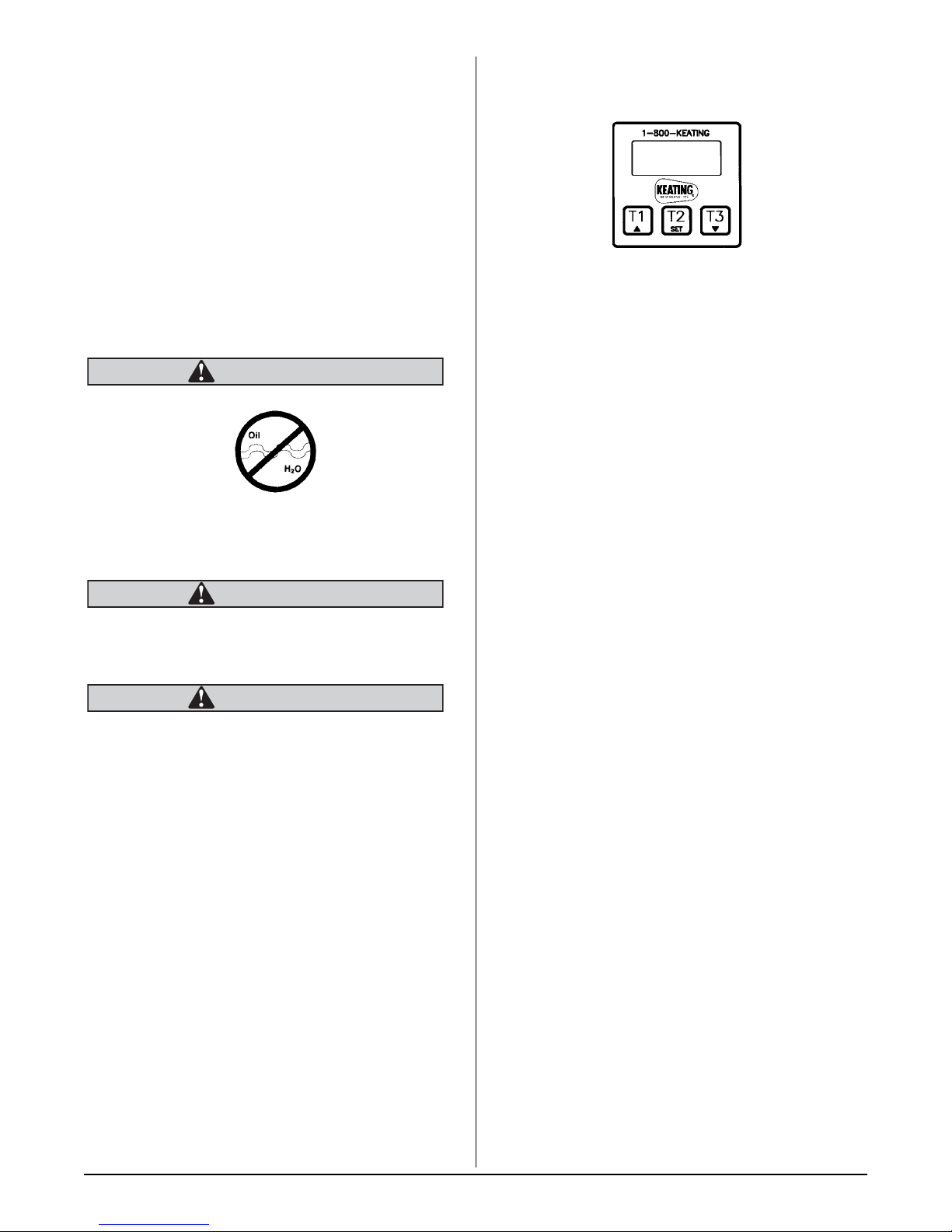
ELECTRONIC TIMERS
13. Thoroughly rinse fryer vessel with potable water
to remove all Klenzer.
14. Prior to refilling with oil, wipe the inside of the
fryer vessel making sure all water and Klenzer
has been removed.
WARNING
WATER IN ANY FORM AND HOT OIL DON’T MIX!!!
15. Close drain valve.
WARNING
FAILURE TO CLOSE DRAIN VALVE BEFORE
REFILLING THE FRYER MAY RESULT IN SERIOUS
INJURY.
WARNING
WHEN YOUR FRYER IS BEING USED IN
CONJUNCTION WITH A CENTRAL FILTER,
DISCONNECT POWER SUPPLY BEFORE
RESETTING MOTOR TO PREVENT SERIOUS
INJURY WHEN RESET SWITCH IS ENGAGED (SEE
FILTER MANUAL).
16. Check thermostat bulb positioning - see page 8.
Figure 3-6
PROGRAMMING
To program the timers, the unit must be in the idle
mode. Press and hold the set button for approximately
two seconds. The display will show “SEt”. Press the
button for the channel to be programmed. The display
will show the current setting for that channel. Use the
up or down button to increment or decrement the
setting. When the setting is correct, press and hold the
set button again for approximately two seconds. The
display will show “StO” for approximately two seconds
and the timer will return to normal operation. Repeat
the process as necessary for other timers.
OPERATING LOGIC
When the timer is powered up, the display will show the
time setting for the channel that was operated last and
the relay output contacts will be open. To start a cycle,
press the desired channel button (1-3). The display will
begin to countdown from the preset time setting and
the relay output contacts will close. During the
countdown, the colon will flash at a one-second rate.
When the countdown has reached “00:00,” the relay
output contacts will open, the display will flash, and the
audible alarm will sound. To cancel the audible alarm,
press any button.
PAUSE FEATURE
17. Refill the fryer with new or filtered oil.
ELECTRONIC CONTROL
TIMERS
The electronic timers provide a clearly visible and
accurate display and are very easy to use.
To pause a cycle in progress, press any button. The
relay output contacts will open, the display will flash,
and the countdown will pause. To resume the
countdown, press any button. The display will resume
the normal countdown and the relay output contacts
will close.
CANCELLING A CYCLE
To cancel a cycle in progress, press and hold any
button for approximately two seconds. The relay output
contacts will open and the display will show the time
setting for the last channel used.
7

MAINTENANCE
WARRANTY REPAIRS
Keating’s warranty begins with the date of installation.
In the event that your fryer, under warranty, needs
repairs other than routine maintenance or cleaning,
you are requested to contact Keating of Chicago (at
1-800-KEATING) before calling a local service
company.
PREVENTIVE MAINTENANCE
Preventive maintenance should be done in daily,
weekly, monthly and yearly intervals as necessary.
Following preventive maintenance procedures will help
keep your fryer working efficiently. Proper care and
servicing will lead to years of quality performance.
2. Allow fryer to cycle three times.
3. Place an accurate thermometer in the oil.
4. If calibration of fryer is found to be less than 15° off,
simply loosen three dial plate retaining screws,
rotate dial plate to match thermometer reading and
tighten screws. For calibration over a 15°F
difference, contact your local service company.
NOTE: Locate thermometer in same position for
every calibration. Position next to upper heating
element is recommended.
C. Thermostat Bulb Positioning
Keating’s patented thermostat application is accurate
within ±7°F of the dial setting between 250°F and
350°F. This accuracy is attained only if the thermostat
bulb is placed properly against the top element using
element clamps. If the bulb is too far away from the
element, the fryer will overshoot.
PREVENTIVE MAINTENANCE CHART
TIME
FRAME
At least
daily
At least
weekly
At least
monthly
At least
yearly
* High production facilities should be checked more often.
OPERATOR/OWNER SECTION
• Check that the oil is up to
“Max Level” line.
• Clear all baskets.
• Drain, strain or filter oil.
• Drain and clean fryer.
• Boil-out fryer.
• Check lights and controls.
• Verify Thermostat settings.
• Test Hi-Limit control.
• Verify all thermostat settings.
• Verify wire connections.
QUALIFIED SERVICE
PERSONNEL ONLY:
• Calibrate thermostat.
A. Oil Breakdown
Overshoot: The thermostat takes a long time to
cycle and then misses its preset temperature by
20°F - 40°F yielding a poor quality product.
OPERATION
OPERATION
MAINTENANCE
MAINTENANCE
& SERVICE
DIAGNOSIS
As part of a “Preventive Maintenance Program”, the oil
in your fryer needs to be filtered regularly to avoid
breakdown. The initial investment in the frying system
is less than the total overall costs of oil during the life of
the fryer, and with regular filtering, you can realize
substantial savings in oil costs as well as maintenance
charges.
B. Limited Calibration (less than 15°F off)
You will need:
One standard flat blade screwdriver
One accurate fryer thermometer
1. Set thermostat to desired frying temperature.
8

SERVICE DIAGNOSIS
A properly adjusted Keating Instant Recovery®Electric Fryer, with no load, will cycle “on” approximately every
1
/2 to 3 minutes. Each cycle will last 15-25 seconds, ensuring that the temperature setting is held within a
2
narrow band.
Every Keating Instant Recovery
guard against component failure.
A. Trouble shooting
The following diagnosis is only to be used as a guide to qualified service personnel. Keating recommends that
you use a qualified service company. Call 1-800-KEATING if you need assistance in locating a qualified service
company.
PROBLEM PROBABLE CAUSE SOLUTION
Fryer won’t heat. a. No electricity to fryer (“POWER ON”
®
Electric Fryer has a number of safety controls to ensure safe operation and
a. Connect fryer to an approved source
switch is off).
of power.
Fryer has poor recovery
or runs cold.
b. No electricity to control circuit
(models with Basket-Lift or Central
Filter).
c. Fryer circuit breakers have tripped.
d. Hi-Limit has been activated.
e. Rear drain valve handle has not been
fully closed (fryers with filter only).
f. On/Off Switch is faulty.
g. Melt-Fry switch is faulty.
h. Contactor is faulty.
i. Thermostat is faulty.
a. Over-filling baskets.
b. Fryer vessel overfilled with oil.
c. Thermostat out of calibration.
b. Connect 120V terminal block to an
approved source of power.
c. Reset circuit breakers.
d. Push in Hi-Limit Reset button located
behind fryer door. Check calibration
of thermostat and operation of HiLimit and contactor.
e. Fully close and latch rear drain valve
handle. Turn fryer OFF and then ON
to restart.
f. Replace On/Off Switch.
g. Replace Melt-Fry Switch.
h. Replace contactor.
i. Replace thermostat.
a. Don’t overfill baskets.
b. Fill fryer up to “Max Level” line as oil
expands when heated.
c. Calibrate thermostat. See page 8–
Calibration.
d. Carbon coating on elements.
e. Element is faulty.
f. Thermostat is faulty.
g. Contactor is faulty.
h. Low incoming voltage.
Fryer is overheating. a. Thermostat bulb improperly placed.
b. Thermostat out of calibration.
d. Boil-out fryer. See page 6 – Cleaning
and Boil-Out.
e. Replace Element.
f. Replace thermostat.
g. Replace contactor.
h. Verify proper incoming voltage.
a. Adjust bulb position. See page 8 –
Thermostat Bulb Positioning.
b. Calibrate thermostat (See page 8 –
Calibration).
9
 Loading...