

Page 1

This Owner’s Guide provides specific operating instructions for your model.
Use the Portable Filter only as instructed in this Service Guide.
PORTABLE FILTER
OWNERS MANUAL
MODELS PC14, LB-100, LB-165, LB-200
1-800-KEATING
www.keatingofchicago.com
Part # 018164
®
Page 2

READ AND SAVE THIS MAN UAL FOR FUTUR E REFERE NCE
Record the Model No. and Serial No. of this Portable Filter in the space provided below.
Serial No. ____________________________________________________________
Model No. ____________________________________________________________
Keep these numbers for future reference
IMPORTANT: Keep a copy of your bill of sale. The date on the bill establishes the warranty period should service
be required. If service is performed, it is in your interest to obtain and keep all receipts. Keating commercial filters
are intended for other than household use.
This Owner’s Guide provides specific operating instructions for your model.
Use the Portable Filter only as instructed in this Service Guide.
KEEP THIS MANUAL FOR TRAINING NEW PERSONNEL
Page 3
PORTABLE FILTER
OPERATING INSTRUCTIONS
1
Figure 1.3: Assemble filter
Figure 1.1: Remove screen over
elements/ tubes
Figure 1.2: Stir with spoon to
remove water
A. PREPARING THE PORTABLE FILTER
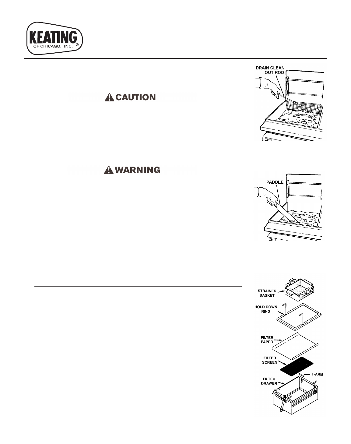
1. Remove screen from over tubes/element with tongs or a Drain Clean Out
Rod (See Figure 1.1).
SCREEN OVER TUBES/ ELEMENTS WILL BE VERY HOT AND
SHOULD BE MOVED TO A SAFE PLACE.
2. Heat fryers to 325°F. Stir oil thoroughly until all water is removed and
shut fryer off (including pilot light) before filtering. (Figure 1.2)
NOTE: Water settles in the cooler oil in the Cold Zone. If the water is not
removed, the filter paper absorbs the water preventing the oil from
passing through it.
OIL IS HOT. USE CARE WHEN FILTERING.
3. Place in clean filter tub (See Figure 1.3):
1st: Filter Screen
2nd: Filter Paper (new sheet for each fryer)
3rd: Hold down ring
4th: Secure hold down ring at each corner with “T” rod handles
5th: Acidox filter powder (new powder for each fryer)
6th: Strainer basket
NOTE: Hold down ring makes a gasket-like seal on filter paper. Filter paper
must be placed edge to edge from front to back, overlapping on
sides. Filter Paper must be smooth and flat under hold down ring to
get a proper seal. Lock the two tension arms into place by pushing
down and rotating 90°.
NOTE: One package of Acidox is needed for every 40 pounds of oil.
B. FILTRATION
1. Place filter under fryer drain. Screw drain extension tube in to drain valve
if desired. Open main drain valve and let oil flow completely into filter
(See Figure 2.1).
2. Turn on pump and flush all crumbs from bottom of fryer into filter. Flush
out fryer completely (See Figure 2.2).
NOTE: Pump should be run for at least 30 seconds after crumbs are
removed from fryer. This will help prevent blockage in the drain lines.
3. Close fryer drain valve (See Figure 2.3).
4. Clean fryer vessel with non-abrasive scrub pad & Keating Klenzer.
5. Fill fryer with filtered oil by turning on pump and directing end of wand
into vessel (See Figure 2.4).
NOTE: Filters with two-way pump - do NOT place wand in cold zone of fryer
pot as it may pick up crumbs & other debris and excessively clog
filter paper.
Page 4

C. CLEAN-UP
FILTER UNIT AND PIPES WILL REMAIN HOT FOLLOWING
FILTRATION. ALLOW THE UNIT TO COOL DOWN BEFORE CLEAN
UP. FAILURE TO DO SO MAY RESULT IN SERIOUS INJURY TO THE
OPERATOR.
1. Turn off filter and disconnect from electrical source.
2. Remove strainer basket and hold down ring for cleaning
3. Remove and discard filter paper and any residue.
4. Clean filter tub thoroughly.
5. Coat inside of pump with oil if water has been running through it.
6. Place hose so that remaining oil will drain out.
D.
MELTING SOLID SHORTENING
1. Clean filter tub and remove all accessories.
2. Place a cube of shortening in filter tub.
3. Turn fat melter on. (50 lbs takes 1 hr to melt)
4. Once shortening is melted fill fryer with oil by turning on pump and
directing end of wand into vessel (See Figure 2.4).
DO NOT ALLOW SHORTENING TO SOLIDIFY IN FILTER AS IT WILL
ALSO SOLIDIFY IN PIPES.
DO NOT TURN ON FAT MELTER WITHOUT SHORTENING IN TUB.
WARRANTY REPAIRS
Keating’s 1 year parts & labor warranty begins with the date of installation.
In the event that your filter, under warranty, needs repairs other than routine
cleaning, you are requested to contact KEATING OF CHICAGO, INC.
(1-800-KEATING) before calling a local service company.
Figure 2.3: Close drain valve
Figure 2.4: Fill fryer with filtered
oil
2
Figure 2.1: Drain fryer
Figure 2.2: Flush out fryer
HOT FLUID. DO NOT FILL
BEYOND MAXIMUM FILL LINE
LOCATED IN THE FRYER VESSE L.
Page 5

SELF-HELP GUIDE
3
PROBLEM PROBABLE CAUSE SOLUTION (Follow Sequentially)
Motor runs but will not pump oil. A. Solidified shortening may have
plugged pipes.
Turn on fat melter for 20 minutes. This will heat
filter tub and pipes to free system of solidified
shortening. Reset motor before attempting filtering
(reset button is located on rear of pump motor).
B. Tub not set up properly. Place components in tub per the following:
1. Filter screen on the very bottom.
2. Filter paper over filter screen (Lie it flat on the
bottom, creasing the sides).
3. Hold down ring (ensure paper is not folded,
lock hold down ring into place ensuring a tight
seal).
4. Sprinkle Acidox powder evenly over filter
paper (1 bag per 40 lbs. of oil).
5. Strainer basket for large debris.
Motor does not operate. A. Not plugged in.
B. Motor has overheated.
C. Motor pump is clogged.
1. Plug filter into a 120 or 220 Vac electrical
power source.
2. Turn ON/OFF switch to ‘ON’.
1. Allow motor to cool for approximately 10
minutes.
2. Press the motor overload reset button and try
again.
1. Call a qualified service technician to clean
your pump. Clogged motor pumps are not
covered by warranty.
Preventitive maintenance should be performed during & after each use of the filter. Following preventative maintenance
procedures will help to keep your filter working efficiently. Proper care & servicing will lead to years of quality performance.
PREVENTIVE MAINTENANCE
Familiarize yourself with the proper filtering procedure prior to attempting to filter:
1. To remove water, stir oil until bubbling stops; water will clog filter paper pores.
2. Use only one sheet of filter paper properly sealed under hold down ring.
3. Do NOT turn on fat melt without oil in filter tub.
4. Use a drain clean out rod if partial or full blockage in fryer drain is suspected.
5. If filter was used for fryer boil out, run oil through filter to lubricate motor/pump.
6. Clean filter and all components after each use. Do not permit oil to remain in filter drawer; it will clog the pump.
7. Verify all lights and controls operate.
8. Adhere to operating instructions in sequence given for proper filtration.
9. Prepare filter for next use by using new filter paper and Acidox Powder for each fryer.
Page 6
DISASSEMBLY
You will need:
Adjustable wrench “Stubby” screwdriver
Standard pliers Standard screwdriver
Servicing should only be performed by qualified and licensed
service companies. Always disconnect the electrical power
cable before attempting any service
The filter maybe hot; use care while servicing. As a
safety precaution, it is recommended you drain oil from
the filter vessel before performing any servicing.
A. MELT AND/OR PUMP INDICATOR LIGHTS
Removal:
1. Disconnect filter from electrical power source.
2. Feel front end panel from bottom to locate rear of
defective indicator light. Note two tangs that extend
slightly beyond indicator light barrel diameter. Use a
standard pliers to squeeze tangs together and pull
indicator light free from panel. If indicator light doesn’t
release, squeeze tighter and break barrel to release
electrical leads. Discard broken pieces.
Replacement:
1. If necessary, clip off electrical leads as close as
possible to indicator light. If leads were clipped, trim
off insulation 1/8 inch from end.
2. With electrical leads extending through panel front,
press them into recesses at rear of replacement
indicator light to secure them in place. Press
indicator light into panel until tangs engage to secure
indicator light to panel.
B. MELT AND/OR PUMP ON/OFF SWITCH
Removal:
1. Disconnect filter from electrical power source.
2. Unscrew nut securing defective switch to panel.
Push switch in to release from panel. Remove
nameplate from front of panel.
3. Access to rear of switch through bottom hole under
front end panel.
4. Disconnect leads from switch. Tag leads as they are
disconnected to assure, during replacement, they are
reconnected to the proper switch terminals.
Replacement:
1. Connect tagged electrical leads to replacement
switch.
2. Insert replacement switch through panel from which
defective switch was removed. Insert nameplate over
toggle and secure to panel with nut supplied with
switch. Orient switch and tighten nut to secure in
desired position.
3. Plug in filter power cord and operate switch to verify
switch orientation corresponds to nameplate legend.
If not, loosen attaching nut and reorient nameplate
and/or switch as desired and retighten nut.
C. MELT CYCLE SENSOR
Removal:
1. Disconnect filter from electrical power source.
NOTE: Remove all oil from filter vessel. Filter must
be positioned on its end to access melt cycle
sensor.
2. Raise front (power cord) end of filter and rest filter on
oil absorbing rags on its back end.
3. Remove bottom cover attaching screws; remove
bottom cover.
4. Remove electrical leads from defective melt cycle
sensor.
5. Loosen heater element cover attaching nut adjacent
to melt cycle sensor sufficiently to release melt cycle
sensor and its retaining plate. Disengage melt cycle
sensor.
Replacement:
1. Orient replacement melt cycle sensor in its retaining
plate such that the metallic sensing surface will be in
direct contact with filter vessel. If necessary, reverse
orientation of retaining plate.
2. Position retaining plate under heater element and tab
on heater element cover with melt cycle sensor
sensing surface in direct contact with filter vessel.
Tighten loosened heater element attaching nut.
3. Attach removed electrical leads to melt cycle sensor.
Verify terminals are not in contact with any metallic
parts of filter vessel, heater cover or heater.
4. Secure bottom cover with removed attaching screws.
5. Position filter right-side-up and clean up oil absorbing
rags.
SERVICE
4
Page 7

5
SERVICE (continued)
E. HEATER ELEMENT(S)
Removal:
1. Disconnect filter from electrical power source.
NOTE: Remove all oil from filter vessel. Filter must
be positioned on its end to access heater
element(s).
2. Raise front (power cord) end of filter and rest filter on
oil absorbing rags on its back end.
3. Remove bottom cover attaching screws; remove
bottom cover.
4. Remove electrical leads from defective heater
element(s). Tag leads as they are disconnected to
assure, during replacement, they are reconnected to
the proper terminals.
5. Loosen heater element(s) cover attaching nuts
sufficiently to release defective heater element(s).
Carefully remove heater element(s) being careful not
to dislodge cover insulator(s).
Replacement:
1. Carefully position replacement heater element(s)
between filter vessel and cover insulator(s).
2. Tighten loosened heater elements cover attaching
nuts to secure heater element(s) in position against
filter vessel.
3. Connect tagged electrical leads to heater element(s).
4. Secure bottom cover with removed attaching screws.
5. Position filter right-side-up and clean up oil absorbing
rags.
F. PUMP AND MOTOR
Removal:
1. Disconnect filter from electrical power source.
NOTE: Remove all oil from filter vessel. Filter must
be positioned on its end to access pump and
motor.
2. Disconnect hand hose assembly from quick
disconnect on discharge port on defective pump and
motor.
3. Raise front (power cord) end of filter and rest filter on
oil absorbing rags on its back end. Remove bottom
cover.
4. Remove attaching screws securing front panel. Tilt
back front panel to expose pump and motor.
5. Remove motor junction box cover and remove
electrical leads from motor terminals. Tag leads as
they are disconnected to assure, during replacement,
they are reconnected to proper terminals.
6. Unscrew coupling nut securing suction tube under
filter vessel from plumbing connected to pump and
motor suction port. Oil absorbing rags should be
available as some oil spillage should be expected.
7. While supporting pump and motor, remove attaching
nuts, flat washers and screws; remove pump and
motor. Note orientation of plumbing elbows at pump
suction port and then unscrew these parts.
8. Remove motor junction box cover and disconnect
electrical leads from motor terminals. Tag leads as
they are disconnected to assure, during replacement,
they are reconnected to the proper terminals.
Replacement:
1. Install removed plumbing parts into replacement
pump and motor suction port in same orientation
noted at removal using teflon tape or a good food
grade pipe joint compound on male threads only of
disassembled plumbing parts.
2. Position pump and motor onto its base and secure
loosely with removed screws, flat washers and nuts.
3. Connect tagged electrical leads to motor terminals.
Install motor junction box cover.
4. Tighten suction tube coupling nut onto mating pump
suction port fitting. Then fully tighten pump and motor
mounting hardware.
5. Position front panel onto frame and secure in position.
Install bottom cover.
6. Position filter right-side-up and clean up oil absorbing
rags.
7. Connect hand hose assembly to quick disconnect on
discharge port.
Page 8

SERVICE (continued)
6
I. HEAT TAPE
Removal:
1. Disconnect filter from electrical power source.
NOTE: Remove all oil from filter vessel. Filter must
be positioned on its end to access heat tape.
2. Raise front (power cord) end of filter and rest filter on
oil absorbing rags on its back end.
3. Remove bottom cover attaching screws; remove
bottom cover.
4. Sketch course defective heat tape follows to assure
oil and various components can be sufficiently heated
during filter operation preventing any solidification.
Then remove heat resistant mastic tape holding heat
tape to filter components.
5. Remove hardware securing heat tape ends to
electrical terminals. Unwind heat tape from filter
components.
Replacement:
1. Wind replacement heat tape onto and around filter
components following same course of removed
defective heat tape.
2. Secure heat tape ends to electrical terminals with
removed hardware.
3. Use a heat resistant mastic tape to secure heat tape
in place on filter components.
4. Secure bottom cover with removed attaching screws.
5. Position filter right-side-up and clean up oil absorbing
rags.
Page 9
7
PORTABLE FILTER
PAR TS LI S T
Parts - LB100 Model
Caster 3” swivel 000626
Caster 3” rigid 000627
Cover for LB-100 (2000 series) 056273
Cover for LB-100 (optional) (pre 2000 series) 000503
Filter screen LB-100 12 1/4” diameter 000591
Indicating Light - Amber 004158
Indicating Light - Red 000525
Handle for cover 004542
Heat Plate 500W 115V 000596
Heat Wrap Tape 4 ft. for LB and PC filters 012055
Hi-Limit Sensor 000694
Hold down Ring Handle 052817
Hold down Ring LB-100 000576
Hold down Ring LB-100 (after 1/2003) 054803
Hose 4 ft. with fittings and Stiffner Spring for
PC14 (for LB filters prior to 2/3/93) 000569
Hose 5 ft. with fittings and Stiffner Spring
(for LB filters after 2/3/93) 018157
Insulation Board 007694
Nozzle 90° with handle for LB and UFF filters 011816
Power Cord 6 ft. with Plug 033559
**Pump/Motor (after 11/88) 008196
**Pump/Motor (after 2003) 055173
Spring for T Handle 006656
Strainer Basket LB100 old style 000668
Switch (Pump-Off-Melt) 000521
Switch Reversing (2-way pump) 000527
Terminal Board 000639
Terminal Board Insulation 000263
Parts - LB165 Model
Caster 3” swivel 000626
Caster 3” rigid 000627
Cord 055241
Cover for LB165 055676
Handle for cover 004542
Heat Plate 500W 115V 000596
Heat Wrap Wire 4 ft. 100W 120V 012055
Hi-Limit Sensor 000694
Hold Down Ring (pre 2000) 016121
Hold Down Ring (pre 2003) 054654
Hose (new style) 055038
Indicating Light - Amber 004158
Indicating Light - Red 000525
Insulation Board 007694
Power Cord Receptacle 055227
**Pump/Motor (after 2004) 055173
**Pump/Motor (2003) 052982
**Pump/Motor (pre 2003) 008196
Screen 001229
Spring for T Handle 006656
**Call 1-800-KEATING with serial # to determine correct part #.
Supplies
Acidox Powder (30 lb case, 60 individual packages) 037524
Filter paper for LB-100 (60 papers) 058783
Filter paper for LB-165 or LB-200 (60 papers) 058781
Filter paper for PC14 058779
Paddle Metal Spoon 029152
Sea Powder (for boiling out fryers), 4 jar case 000394
Sea Powder, 4 jar case (6 cases and up) 000395
ORDERING PARTS
Parts may be ordered by part number by calling your local
service company or Keating at 1-800-KEATING. You may
also order on-line at Keating’s part store,
www.keatingofchicago.com.
Refer to the Keating Filter Limited Warranty for warranty
service information.
The model/serial plate is located on the side of unit. The
serial and model numbers are necessary when ordering.
WARNING AND OPERATING PLATES
All warning and operating plates on the Keating Filter should
be in place at all times.
Page 10
8
PORTABLE FILTER
PAR TS L I S T
Parts - LB165 Model (continued)
Strainer Basket LB165 000677
Switch (Pump-off-melt) 000521
Switch Reversing (2-Way Pump) 000527
Terminal Block 002065
Terminal Board 000639
Terminal Board Insulation 000263
Parts - LB200 Model
Caster 3” swivel 000626
Cover for LB200 056258
Handle for cover 004542
Heat Plate 500W 115V 000596
Heat Wrap Wire 4 ft. 100W 120V 012055
Hi-Limit Sensor 000694
Hold Down Ring (after 2004) 053033
Hold Down Ring (pre 2000) 016121
Hold Down Ring (pre 2003) 054654
Hose 5 ft. with fittings 055038
Indicating Light - Amber 004158
Indicating Light - Red 000525
Insulation Board 007694
Power Cord Receptacle 055227
**Pump/Motor (after 2004) 055173
**Pump/Motor (2003) 052982
**Pump/Motor (pre 1993) 008196
**Pump/Motor (1993) 010567
Screen 001229
Strainer Basket LB200 016305
Switch (Pump-off-melt) 000521
Switch Reversing (2-way pump) 000527
Valve (2-way pump) 000611
Terminal Board 000639
Terminal Board Insulation 000263
Parts - PC14 Model
Caster 3” swivel 000626
Caster 3” rigid 000627
Cord Power 6 ft. 033559
Handle ‘T’ 010628
Heat Plate 500W 115V 000596
Heat Wrap Wire 4 ft. 100W 120V 012055
Hi-Limit Sensor 000694
Hold down Ring 011370
Hose 4 ft. with nozzle & fittings 017640
Indicating Light - Red 000525
Insulation Board 007694
Pump/Motor 008196
Screen 005871
Spring for ‘T’ Handle 006656
Strainer Basket PC14 012054
Switch (Pump-off-melt) 000521
Terminal Board 000639
Terminal Board Insulation 000263
**Call 1-800-KEATING with serial # to determine correct part #.
Page 11
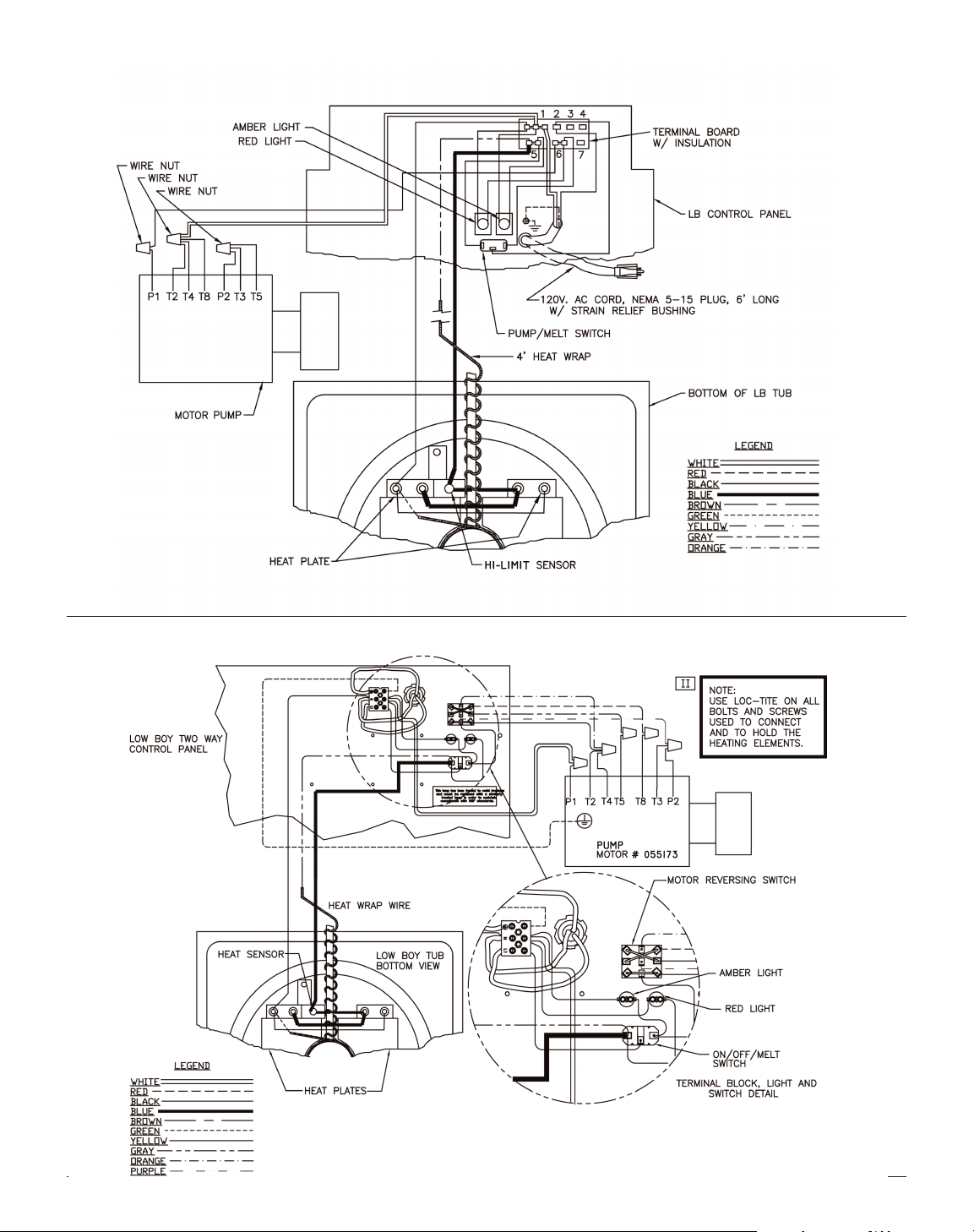
LB100, LB165, LB200 1 Way Pump - Part # 008196
LB100, LB165, & LB200 2 Way Pump - Pump Part # 055173 (1988 - 2002)
9
Page 12
10
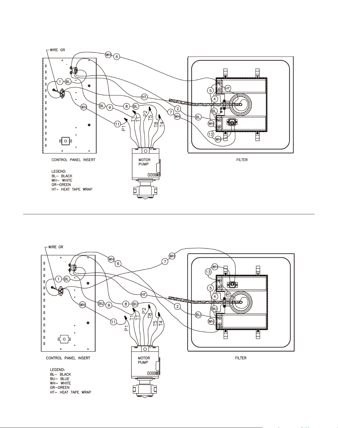
LB165 & LB200 1 Way Pump (model 2004 series) - Pump Part # 055173
LB165 & LB200 1 Way Pump (after 2005) - Pump Part # 055173
Page 13
11
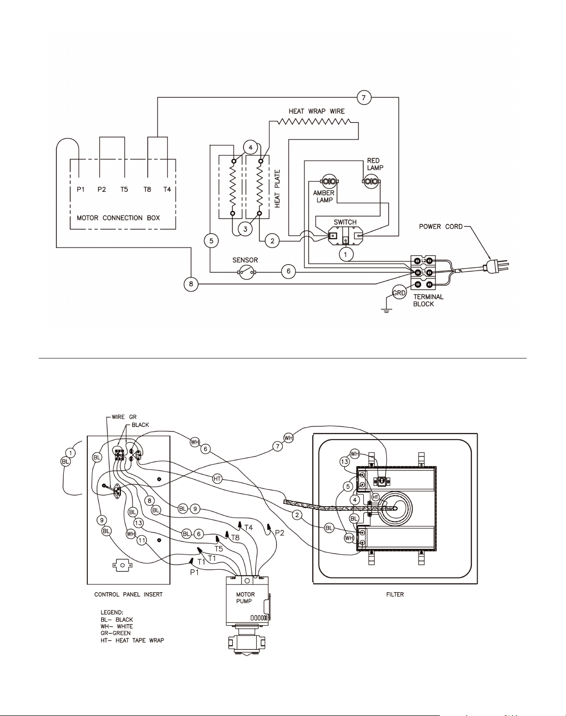
LB165 & LB200 1 Way Pump (model 2003 series) - Pump Part # 052982
LB165 & LB200 2 Way Pump - Pump (after 2004) - Pump Part # 055173
Page 14
12
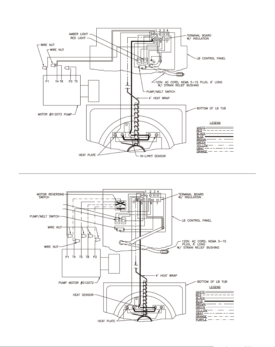
LB200 1 Way Pump - Pump Part # 010567 (1993)
LB200 2 Way Pump - Pump Part # 010567 (1993)
Page 15
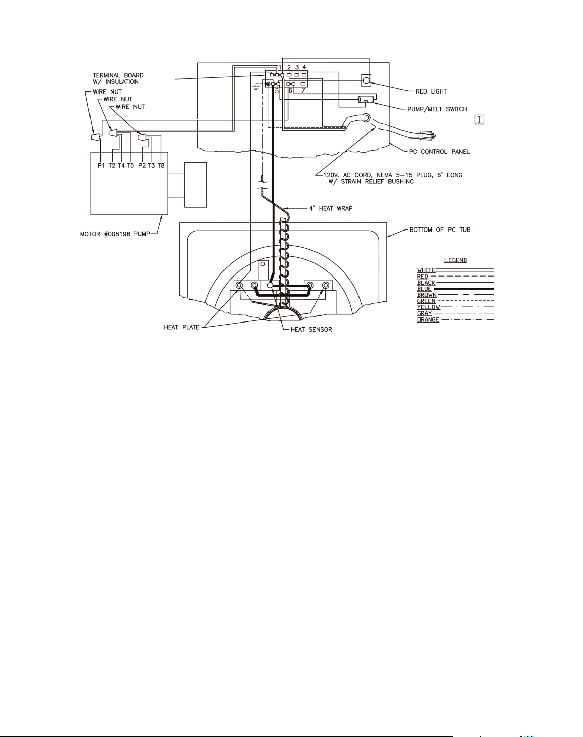
13
PC14
Page 16
LIMITED W
ARRANTY
Keating Of Chicago, Inc. ("Keating”) warrants to the original purchaser. ("Customer"), all new Keating Fryers, Filter Systems, Griddles, Keep Krisp®, Custom Pasta Systems, Top-Side™ Cookers, Computer Timers, Fryer
& Pasta Vessels, and Keating replacement parts ("products") installed after June 1, 1994 to be free to defects in material or workmanship, subject to the following terms and conditions.
LENGTH OF WARRANTY
All products other than Fryer & Pasta Vessels and replacement parts shall be warranted for a period of one year from the date of original equipment installation. Keating replacement parts are warranted for a period of ninety
days from the date of installation. Fryer & Pasta Vessels are warranted as described below.
FRYER & PASTA
VESSEL WARRANTY
Fryers purchased after June 1, 1994 carry a prorated vessel warranty on defects in materials or workmanship to the Customer based on the following scale:
Time from Installation Date Fryer Vessel Warranty Credit
13-60 months 100%
61-72 months 80%
73-84 months 60%
85-96 months 40%
97-108 months 20%
109-120 months 10%
The credit for the defective fryer & pasta vessel shall be applied against the cost of the replacement vessel, utilizing Keating's then current price, upon return of the vessel to Keating, freight to be paid by Keating, only during
the first 60 months, subject to the limitations described below.
LIMITATIONS OF LIABILITY
In the event of warranty claim or otherwise, the sole obligation of Keating shall be the repair and/or replacement at the option of Keating of the product or component or part thereof. Such repair or replacement shall be at the
expense of Keating except that the Customer shall pay the following expenses: all freight and labor expense for Keating replacement parts; for all other products, mileage exceeding 50 miles or travel more than one hour, labor
costs of more than one person, overtime rates, truck charges, difference between ground and other mode of transportation, and holiday charges. Any repair or replacement under this Limited Warranty does not constitute an
extension of the original warranty for any period for the product or for any component or part thereof. Parts to be replaced under this Limited Warranty will be repaired at the option of Keating with new or functionally operative
parts. Keep Krisps and Computer Timers must be returned to Keating for warranty repair or replacement. Field repairs of those items are not authorized.
THE LIABILITY OF KEATING ON ANY CLAIM OF ANY KIND, INCLUDING CLAIMS BASED ON WARRANTY, EXPRESSED OR IMPLIED, CONTRACT, NEGLIGENCE, STRICT LIABILITY OR ANY OTHER
THEORIES SHALL BE SOLELY AND EXCLUSIVELY THE REPAIR OR REPLACEMENT OF THE PRODUCT AS STATED HEREIN, AND SUCH LIABILITY SHALL NOT INCLUDE, AND CUSTOMER
SPECIFICALLY RENOUNCES ANY RIGHTS TO RECOVER, SPECIAL, INCIDENTAL, CONSEQUENTIAL OR OTHER INJURIES TO PERSONS OR DAMAGE TO PROPERTY, LOSS OF PROFITS OR
ANTICIPATED PROFITS, OR LOSS OF USE OF THE PRODUCT.
If any oral statements have been made regarding the Keating products, such statements do not constitute warranties and are not part of the contract sale. This Limited Warranty constitutes the complete, final and exclusive
statement with regard to warranties.
THIS LIMITED WARRANTY IS EXCLUSIVE AND IS IN LIEU OF ALL OTHER WARRANTIES WHETHER WRITTEN, ORAL, STATUTORY OR IMPLIED, INCLUDING BUT NOT LIMITED TO ANY
WARRANTY OF MERCHANTABILITY OR FITNESS FOR PARTICULAR PURPOSE OR WARRANTY AGAINST LATENT DEFECTS.
EXCLUSIONS
The warranties provided by Keating of Chicago, Inc. do not apply in the following instances:
1. Defects arising out of or resulting from improper installation or maintenance, abuse, misuse, modification or alteration by unauthorized service personnel, or any other condition not attributable to a defect in material or
workmanship. Proper installation and maintenance are the responsibility of the installer and Customer, respectively. Proper installation and maintenance procedures are prescribed by the Keating Service Manual.
2. In the event that the product was damaged after leaving the factory due to flood, fire, other acts of God or accident, damage during shipment should be reported to the carrier and is not the responsibility of Keating.
3. In the event the serial number or rating plate has been removed from the product or altered.
4. On parts which would normally be worn or replaced under normal conditions, including but not limited to electric bulbs, fuses, interior and exterior finishes, gaskets, radiants, sensors, etc.
5. With regard to adjustments and calibrations such as leveling, tightening of fasteners or plumbing connections, improper gas pressure or improper electrical supply, the checking of and changes in adjustment and
calibrations are the responsibility of the installer. Proper installation procedures are prescribed by the Keating Service Manual.
6. In the event of unauthorized repairs or alterations to the Keating product.
7. With the use of sodium chloride in pasta vessels or harsh chemicals in fryer or pasta vessels.
OTHER
TERMS AND CONDITIONS
The Customer must provide proof of purchase from Keating.
This Limited Warranty is valid in the 50 United States, its territories, and Canada, and is void elsewhere.
Keating products are sold for commercial use only. If any Keating product is sold as a component of another product or used as a consumer product, such Keating product is sold As Is without any warranty.
If any provision of this Limited Warranty is held to be unenforceable under the law of any jurisdiction, such provision shall be inapplicable in such jurisdiction, and the remainder of the warranty shall remain unaffected.
Further in such event, the maximum exclusion or limitation allowable under applicable law shall be deemed substituted for the unenforceable provision.
This Limited Warranty shall be governed by and construed in accordance with the laws of the State of Illinois.
TO SECURE WARRANTY SERVICE
All repair services under this Limited Warranty must be authorized by Keating or performed at Keating. Authorization may be obtained by calling 1-800-KEATING within the Continental United States, Alaska, Hawaii, Puerto
Rico and Canada during normal business hours (8:00 a.m. through 5:00 p.m. Central Time, Monday through Friday). When calling, please have the following information available: (1) name, address and
telephone number of the Customer; (2) location of product, if different; (3) name, model number and serial number of the product; (4) installation date; and (5) description of defect. Keating will then issue a service
authorization work order number to one of its approved independent servicing organizations, or request the product or part be shipped to Keating for repair or replacement, as appropriate. Any defective part subject to a claim
under this Limited Warranty must be shipped freight prepaid to Keating for testing and examination. Keating's decision as to the cause and nature of any defect under this Limited Warranty shall be final.
KEATING
KEATING OF CHICAGO, INC., 1-800-KEATING WWW.KEATINGOFCHICAGO.COM
REFILE/warranty 3/01
WARRANTY
Page 17

KEATING LIMITED WARRANTY CARD
PLEASE COMPLETE AND MAIL AT ONCE–WARRANTY IS NOT IN EFFECT UNTIL CARD IS RETURNED
WARRANTY CARD IS ALSO AVAILABLE ONLINE FOR YOUR CONVENIENCE
COMPANY: ________________________________________________________________________________________________________________________
ADDRESS:__________________________________________________________________________________________________________________________
CITY: ______________________________________________________________________________ STATE: ________________ ZI P:____________________
DEALER: __________________________________________________________________________________________________________________________
DATE OF PURCHASE: ________________________________________________________________ I NVOICE NUMBER:____________________________
SERIAL NUMBER:________________________________________ FRYER FI LTER SYSTEM GRIDDLE
REMAR KS: ______________________________________________ TOP-SIDE COOKER HOT PLATE PASTA PLUS
I HAVE READ THE INSTALLATION AND OPERATION INSTRUCTIONS.
SIGNED: __________________________________________________________________________________ DATE: ________________________________
SERVICE INFORMATION
If you have a service related question call 1-800-KEATING.
Please state the nature of the call; it will ensure speaking with the appropriate person.
Have your serial and model number available when ordering parts.
KEATING OF CHICAGO, INC.
8901 West 50th Street, McCook, Illinois 60525-6001
Phone: (708) 246-3000 FAX: (708) 246-3000
Toll Free 1-800-KEATING (In U.S. and Canada)
www.keatingofchicago.com
*As continuous product improvement occurs, specifications may be changed without notice.
“Serving Those Who Serve The Very Best”
®
PortableFilter 9/08
 Loading...