

Page 1

1-800-KEATING
www.keatingofchicago.com
Users Manual
TOP SIDE™ COOKER
SERIES 2005
READ AND SAVE THIS MANUAL FOR FUTURE REFERENCE.
Keep this manual for training new personnel.
IMPORTANT: Keep a copy of your bill of sale. The date on the bill establishes the warranty period should
service be required. If service is performed, it is in your interest to obtain and keep all receipts. Keating
commercial griddles are not intended for household use.
The Owner’s Guide provides specific operating instructions for your model. Use the Top Side™ Cooker
only as instructed in this Service Guide.
topSideCooker2005
04/11
RECORD THE MODEL AND SERIAL
NUMBERS OF THIS TOP SIDE™COOKER
IN THE SPACES PROVIDED.
SERIAL NO. ______________________________
MODE L NO. _____________________________
KEEP THESE NUMBERS FOR FUTURE REFERENCE.
SECTION I: INTRODUCTION
GEN ERAL . . . . . . . . . . . . . . . . . . . . . . . . . . . . . . . . . . . . . . . . . . . . . . .1
STANDARD FEATURES . . . . . . . . . . . . . . . . . . . . . . . . . . . . . . . . . . . .1
STANDARD ACCESSORIES . . . . . . . . . . . . . . . . . . . . . . . . . . . . . . .1
COOKI NG HEAD SPECIFICATIONS . . . . . . . . . . . . . . . . . . . . . . . .1
SAFETY PRECAUTIONS . . . . . . . . . . . . . . . . . . . . . . . . . . . . . . . . . . .1
SECTION II: INSTALLATION
DAMAGE DURING SHIPMENT . . . . . . . . . . . . . . . . . . . . . . . . . . . . .1
INSTALLATION . . . . . . . . . . . . . . . . . . . . . . . . . . . . . . . . . . . . . . . . . . . .1
CONDITIONING THE GRIDDLE . . . . . . . . . . . . . . . . . . . . . . . . . . . .2
ELECTRICAL CONNECTION . . . . . . . . . . . . . . . . . . . . . . . . . . . . . . .2
SECTION III: OPERATING
COOKI NG . . . . . . . . . . . . . . . . . . . . . . . . . . . . . . . . . . . . . . . . . . . . . . .2
COOKI NG HEIGHT ADJUSTMENT . . . . . . . . . . . . . . . . . . . . . . . . .2
DIGITAL TIMER PROGRAMMING . . . . . . . . . . . . . . . . . . . . . . . . . . .2
SHUTDOWN . . . . . . . . . . . . . . . . . . . . . . . . . . . . . . . . . . . . . . . . . . . . .3
CLEANING PROCEDURES . . . . . . . . . . . . . . . . . . . . . . . . . . . . . . . .3
A. KEATING COOKING SHEET . . . . . . . . . . . . . . . . . . . . . . . . . . .3
B. COOKING SHEET CLIPS . . . . . . . . . . . . . . . . . . . . . . . . . . . . .3
C. COOKING HEAD . . . . . . . . . . . . . . . . . . . . . . . . . . . . . . . . . . . . .3
SECTION IV: MAINTENANCE
WARRANTY REPAIRS . . . . . . . . . . . . . . . . . . . . . . . . . . . . . . . . . . . . .4
PREVENTIVE MAINTENANCE . . . . . . . . . . . . . . . . . . . . . . . . . . . . . .4
INSTALLING A COOKING SHEET . . . . . . . . . . . . . . . . . . . . . . . . . .5
HANDLING COOKING SHEETS . . . . . . . . . . . . . . . . . . . . . . . . . . . .5
LEVELING OF COOKING HEAD . . . . . . . . . . . . . . . . . . . . . . . . . . . .5
REMOVAL OF COOKING HEAD . . . . . . . . . . . . . . . . . . . . . . . . . . . .5
SECTION V: SERVICE DIAGNOSIS
TROUB LE-SHOOTING CHART . . . . . . . . . . . . . . . . . . . . . . . . . . . . .6
TROUB LE-SHOOTING THE THERMOSTAT . . . . . . . . . . . . . . . . . .7
SECTION VI: PARTS LIST
ORDE RING PARTS . . . . . . . . . . . . . . . . . . . . . . . . . . . . . . . . . . . . . . .8
WARNING AND OPERATING PLATES . . . . . . . . . . . . . . . . . . . . . . .8
TOP-SIDETMMANUAL COOKING HEAD (EXPLODED VIEW) . . .8
TOP-SIDETMCOOKI NG HEAD PARTS LIST . . . . . . . . . . . . . . . . . . .9
TOP-SIDE™ AUTO-LIFT COOKING HEAD . . . . . . . . . . . . . . . . . . .10
TOP-SIDE™ AUTO-LIFT ACTUATOR MICROSWITCH . . . . . . . . .11
CONTROL PANEL ASSEMBLY . . . . . . . . . . . . . . . . . . . . . . . . . . . .12
POWER SUPPLY BOX AUTO-LIFT HEAD . . . . . . . . . . . . . . . .13-14
SECTION VII: WIRING DIAGRAM
WIRING DIAGRAMS . . . . . . . . . . . . . . . . . . . . . . . . . . . . . . . . . .15-18
CONTENTS:
part# 037621
Page 2
NOTICE: This operating, installation, and service manual should be given to the user. The operator of the Top-
Side Cooker
™
should be familiar with its functions and operation. This manual must be kept in a prominent, easily
reachable location near the Top-Side Cooker
™
.
NOTICE: Keating of Chicago, Inc. (manufacturer) reserves the right to change specifications at any time.
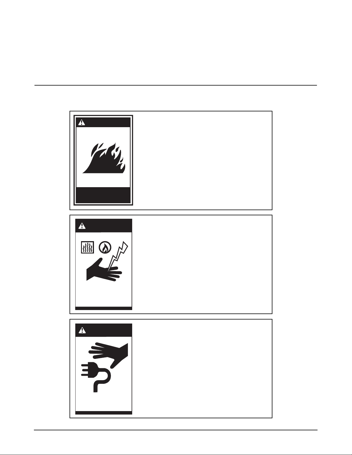
B
WARNING
Improper installation
can cause damage,
injury or death.
ShockBurnsGas
DO NOT STORE OR USE GASOLINE
OR OTHER FLAMMABLE VAPORS
OR LIQUIDS IN THE VICINITY OF THIS
OR ANY OTHER APPLIANCE.
IMPROPER INSTALLATION,
ADJUSTMENT, ALTERATION,
SERVICE OR MAINTENANCE CAN
CAUSE PROPERTY DAMAGE,
INJURY OR DEATH. READ THE
INSTALLATION, OPERATING AND
MAINTENANCE INSTRUCTIONS
THOROUGHLY BEFORE INSTALLING
OR SERVICING THIS EQUIPMENT.
WARNING
Disconnect all power
before servicing.
000000
BEFORE OBTAINING ACCESS TO
TERMINALS, ALL SUPPLY CIRCUITS
MUST BE DISCONNECTED.
WARNING
Do not store flammable
liquids near this or any
other appliance.
Page 3
1
I INTRODUCTION
GENERAL
Keating Top-Side™Cookers are designed to give
maximum production efficiency, delivering high quality
food products. The following design features are
incorporated into Keating Top-Side™Cookers.
STANDARD
FEATURES
Stainless steel control panel
Stainless steel head cover
MIRACLEAN
®
cooking surface
Solid State Thermostat
Adjustable cooking height, from
1
/8'' to 11/2'' (3mm to
38mm)
Locking mechanism for micro-level
STANDARD
ACCESSORIES
Proprietary USDA and UL listed polymer cooking
sheets (1)
NOTE: Keating of Chicago, Inc. (manufacturer)
reserves the right to change specifications at any time.
COOKING HEAD
SPECIFICATIONS
Each Top-SideTMcooking head is designed to be
connected to a 208, 220 or 240 volt single phase line.
STANDARD
TOP-SIDE™
COOKERS
Sizes: 1 to 6 heads.
Mounting: Can be mounted to any standard
MIRACLEAN
®
gas or electric 30'' (762mm) deep
griddle (24'' deep plate / 610mm) up to 72" wide (up to
6 heads maximum). Front trough only griddles are
preferred for multiple heads.
Cooking Surface: 10
1
/2'' (267mm) wide x 20'' (508mm)
deep (per cooking head).
Number of heads: One head can be used for every 12''
(305mm) of plate width. Each Top-Side™cooking head
will be positioned over a griddle thermostat to ensure
peak efficiency.
ETL and ETL Sanitation listed.
SAFETY
PRECAUTIONS
THIS SYMBOL WARNS YOU THAT SERIOUS
BURNS OR OTHER INJURIES MAY RESULT IF
SAFETY INSTRUCTIONS ARE NOT FOLLOWED.
DO NOT SUBMERGE THE TOP-SIDE
™
COOKING
HEAD IN WATER.
CLEANING CHEMICALS OR UTENSILS USED
FOR CLEANING GRIDDLES WILL DAMAGE OR
DESTROY THE POLYMER COOKING SHEET.
NEVER USE A WATER JET TO CLEAN.
II INSTALLATION
This Top-Side™Cooker MUST be installed on a Keating
griddle only. Failure to do so voids the warranty.
The Top-Side
™
Cooker must be installed, inspected,
calibrated and serviced by qualified, certified and/or
licensed service personnel. Contact your dealer for
assistance.
DAMAGE DURING
SHIPMENT
The Top-Side™Cooker has been assembled, tested and
inspected at the factory. Upon arrival, the complete TopSide
™
Cooker should be thoroughly checked for any
damage that may have occurred during shipment.
What to do if equipment arrives damaged:
VISIBLE LOSS OR DAMAGE- Be certain to note this on
the freight or express receipt and have it signed by the
delivery person.
FILE CLAIM FOR DAMAGES IMMEDIATELYRegardless of extent of damage.
CONCEALED LOSS OR DAMAGE- If the damage is
noticed when the equipment is unpacked, notify the
freight company immediately, and file a “concealed
damage claim”. This MUST be done immediately. Be
sure to retain the shipping container for inspection.
Keating does not assume responsibility for loss OR
damage incurred in transit.
INSTALLATION
On new installations, your Top-Side™ Cooker has already
been factory installed, tested leveled and inspected. TopSide™ Cookers cannot be mounted onto existing Miraclean®
griddles in the field.
HEIGHT WIDTH DEPTH WATTS AMPS kW
3 5/8"
(92mm)
10 1/2"
(267mm)
20"
(508mm)
4,000
@220V18@220V
4.0
@220V
Page 4
2
ELECTRICAL
CONNECTION
Each Keating Top-Side™Cooking head is equipped
with a 9' (2.74m) neoprene covered, 12 gauge 4mm(2),
three wire with ground electrical cord. Each cooking
head is rated 4000W, 18 amps, single phase at 220
Volts and is designed to be connected to its own 208240V single phase electrical supply. For proper
connecting and grounding procedure see local codes,
the National Electrical Code ANSI/NFPA 70 (latest
edition) or Canadian Electrical Code CAN C22.1 (latest
edition) as applicable.
THIS APPLIANCE MUST BE EARTHED.
III OPERATING
Food will cook much faster with a Top-Side™Cooker
than with a griddle alone. Watch food while cooking or
use timers to ensure food will not be overcooked.
OPERATION OF THE TOP-SIDE
™
COOKER
SHOULD BE LIMITED TO PERSONNEL
THOROUGHLY TRAINED IN OPERATING
PROCEDURES.
CONDITIONING THE
GRIDDLE
The MIRACLEAN®Griddle plate has been “seasoned”
at the factory. The chrome surface when heated
creates a thin layer of chrome oxide which acts as a
releasing agent for food products. If you feel you need
to recondition the surface, the following instructions
should be followed:
1. Follow cleaning instructions on this page & next.
2. Heat the MIRACLEAN
®
to 400°F for one hour.
3. Lower thermostat to 350°F, allowing the
MIRACLEAN®to cool to about 350°F, as is evident
when griddle cycles on or surface thermometer
indicates correct temperature.
4. Lightly coat the MIRACLEAN
®
surface with griddle
oil.
NOTE: Despite the food releasing properties, the
chrome surface is not a true “non-stick” surface. For
best cooking results and product appearance, use
griddle oil for products that require the surface to be
conditioned.
COOKING
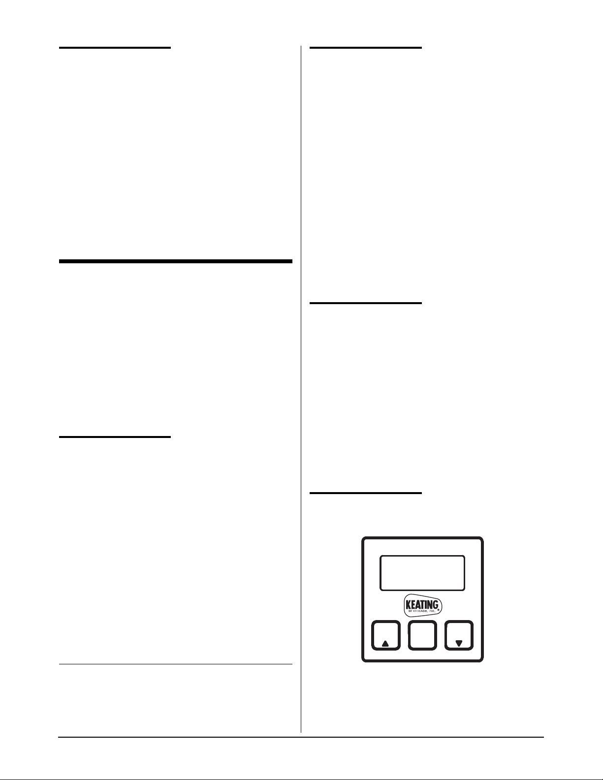
1. Turn ON/OFF switch to “ON” position.
2. Press and hold the “Push to Set” button on the
thermostat and adjust the knob to the desired
temperature. The new temperature will be entered
after 3 seconds. Red “ELEMENT ON” light will
illuminate when the element is on.
NOTE: To increase temperature, adjust knob
clockwise. To decrease, adjust knob
counterclockwise.
Figure 3-1
Top-Side
TM
Cooker Control Panel
COOKING HEIGHT
ADJUSTMENT
Keating’s Top-Side™Cooker has been designed to
allow you infinite height adjustments from 1/8'' to 11/2 ''
(approximately 3mm to 38mm). An adjusting knob
allows fast and precise height adjustment.
Clockwise movement of the knob will decrease the
spacing; counter clockwise movement will increase the
spacing. Each turn of the adjusting knob represents
1/8'' (approximately 3mm) movement.
Experimentation will give you the best cooking height
for each type of food product. The cooking head should
contact the product firmly to ensure optimum heat
distribution without flattening the product.
DIGITAL TIMER
PROGRAMMING FOR
AUTO-LIFT HEADS
ONLY
The electronic timers provide a clearly visible and
accurate display and are very easy to use. Three
different, independent cook times can be set using this
timer - T1, T2 and T3. When cook time has reached
“00:00”, the cooking head will automatically raise.
T3T2
SET
T1
1-800-KEATING
Page 5

3
Programming
To program the timers, the unit must be in the idle
mode. Press and hold the set button for approximately
two seconds. The display will show “SEt”. Press T1, T2
or T3 for the cook time to be programmed. The display
will show the current setting for that cook time. Use the
up or down button to increment or decrement the
setting. When the setting is correct, press and hold the
set button again for approximately two seconds. The
display will show "StO" for approximately two seconds
and the timer will return to normal operation. Repeat
the process as necessary for the other timers.
Operating Logic
When the timer is powered up, the display will show the
time setting for the channel that was operated last and
the relay output contacts will be open. To start a cycle,
press the desired cook time button (T1, T2 or T3). The
display will begin to countdown from the preset time
setting and the relay output contacts will close. During
the countdown the colon will flash at a one-second
rate. When the countdown has reached "00:00" the
relay output contacts will open, the display will flash,
and the audible alarm will sound. To cancel the audible
alarm, press any button.
Pause Feature
To pause a cycle in progress, press any button. The
relay output contacts will open, the display will flash,
and the countdown will pause. To resume the
countdown, press any button. The display will resume
the normal countdown and the relay output contacts
will close.
SHUTDOWN
Turn ON/OFF switch to “OFF” position.
CLEANING
PROCEDURES
A. Keating Cooking Sheets
Clean cooking sheets with a damp soft cloth after
each run of product (a Turkish towel works best).
THE COOKING HEAD WILL BE HOT. USE PROPER
CARE WHEN CLEANING THE COOKING SHEETS.
End of day cleaning:
Before the griddle is turned off for the day, the cooking
sheets should be cleaned as described below. Wear
heat resistant gloves for maximum safety during the
entire cleaning procedure.
1. At the end of the day, wipe the cooking sheet in
place with a damp soft cloth. Continue wiping until
the surface of the cooking sheet is free of any residue.
2. Remove the cooking sheet from the cooking head.
Clean the cooking head and the griddle surfaces.
3. Wash the cooking sheet with a mild detergent in
warm water and dry thoroughly.
4. If needed, after the cleaning is complete, reverse
the cooking sheet and reattach it to the cooking
head.
B. Cooking Sheet Clips
To remove the stainless steel cooking sheet clips for
cleaning, simply lift them off. They can be cleaned in a
dishwasher.
C. Cooking Head
The MIRACLEAN
®
surface is very durable and with
proper care, following the procedures below, will last
many years.
1. Scrape MIRACLEAN
®
surface from front to back
with the Keating griddle scraper with Cooking
Sheets removed.
2. Clean and polish surface with Keating Klenzer on a
damp soft cotton cloth. Wipe off excess Klenzer.
BECAUSE OF THE SUPERIOR MIRACLEAN
®
SURFACE, THE ONLY TOOLS YOU WILL EVER NEED
TO CLEAN THE TOP-SIDE
™
COOKING HEAD ARE A
DAMP SOFT COTTON CLOTH AND A KEATING
SCRAPER.
NEVER SCRAPE COOKING SHEETS WITH THE
SCRAPER.
NEVER USE A GRIDDLE STONE, BRICK,
GRIDDLE SCREEN OR HARSH CHEMICALS TO
CLEAN THE MIRACLEAN
®
SURFACE.
DAMAGE DONE TO THE MIRACLEAN
®
SURFACE
BY GRIDDLE STONE, BRICK, SCREEN, OR
HARSH CHEMICALS WILL VOID THE WARRANTY.
THE DAMAGE DONE TO THE MIRACLEAN
®
SURFACE IS IRREPARABLE.
NEVER USE ICE TO COOL THE MIRACLEAN
®
SURFACE AS IT MAY WARP THE MIRACLEAN
®
SURFACE.
USE ONLY KEATING SUPPLIED CLEANING
TOOLS AND KLENZER.
USE ONLY A KEATING STEEL SPATULA.
NOTE: Keating Klenzer MSDS Sheet available on
website, www.keatingofchicago.com
Page 6

4
Do not hack, chop or hit the surface. You will dent the
steel plate under the trivalent chrome. It is even
possible to hack two nicks close together and actually
tear the MIRACLEAN
®
surface as the chromium will not
stretch. Below is a sketch showing a side view of a
cooking head and how the surface can be damaged.
Proper use of the utensils supplied with your
MIRACLEAN
®
Griddle will prevent surface damage.
Surface Damage
IV MAINTENANCE
WARRANTY REPAIRS
Keating’s warranty begins with the date of installation.
In the event your Keating Top-Side™Cooker needs
repair under warranty other than routine maintenance
or cleaning you are requested to contact KEATING OF
CHICAGO, INC. at 1-800-KEATING before calling a
local service company.
NOTE: The cooking sheets are not covered under
warranty.
PREVENTIVE
MAINTENANCE
Preventive maintenance should be done in daily,
weekly, monthly and yearly intervals as necessary.
Following preventive maintenance procedures will help
keep your Top-Side
™
Cooker working efficiently. Proper
care and servicing will lead to years of quality
performance.
Proper care should be taken to fully clean the TopSide
™
Cooker on a regular basis. The control panel
should be cleaned of any greasy residue with a damp
cotton cloth. Remove any residue from the ON/OFF
switch and the thermostat. Wipe down the cabinet,
sides and back on a regular basis.
TIME
FRAME
OPERATOR/OWNER SECTION
At Least
Daily
• Clean all cooking sheets.
• Clean MIRACLEAN
®
Griddle
surface.
III
At Least
Weekly*
• Clean all surfaces of
Top-Side
™
Cooker.
III
Monthly* • Verify thermostat settings.
• Review cooking procedures.
• Check Cooking Sheets
(Replace if necessary).
IV & V
III
At Least
Yearly*
QUALIFIED SERVICE
PERSONNEL ONLY
• Thoroughly check and test
Top-Side
™
Cooker.
• Calibrate controls.
IV & V
*High production facilities should be checked more often.
Contact the factory or a local service company to perform
maintenance and repairs.
Page 7

INSTALLING A
COOKING SEET
1. Raise Top-Side™Cooking head completely.
2. Lay the 20'' x 24'' (508mm x 610mm) cooking sheet
on the griddle plate with 20'' (508mm) dimension
front to back.
3. Lower the Top-Side
™
Cooker head onto the cooking
sheet, ensuring that the sheet is centered under the
head, the front edge of the sheet is even with the
front edge of the head, and the sides of the sheet
are parallel to the side of the head.
4. Fold both edges of the cooking sheet over the head.
While gently pulling the right side of the sheet to
remove any slack, firmly push the cooking sheet
mounting clip onto the right side mounting rib on top
of the head.
5. Repeat process on the left side.
6. Reverse the process to remove the cooking sheet.
TIPS ON PROPER
HANDLING AND USE
OF COOKING SHEETS
To ensure long life of your Keating cooking sheets
please follow the tips below:
Cooking sheets should never:
Be folded or creased.
Be touched with sharp objects.
Come in contact with griddle scrapers or abrasive pads.
Be placed under other equipment or objects.
Cooking sheets should always:
Be wiped with a damp soft cotton cloth after each run
to remove any product residue.
Be cleaned after the griddle is shut down for the day.
The time to change a Cooking Sheet is when:
Product starts sticking to the sheet.
Too much carbon build-up causes a product
appearance, cooking or taste problem.
The head surface is cool.
The sheet is torn or ripped.
THE TOP-SIDE
™
COOKING HEAD AND GRIDDLE
PLATE ARE HOT - USE PROPER CARE WHEN
CHANGING THE COOKING SHEETS.
LEVELING OF
COOKING HEAD(S)
The cooking head(s) were leveled at the factory.
NOTE: For best results, level griddle before
checking. Adjust legs or stand casters to level griddle.
REMOVAL OF
COOKING HEAD
NOTE: To identify parts, refer to page 8.
1. Turn off griddle and disconnect Top-Side
™
Cooker
electric power.
2. Remove the cooking sheet by lifting off cooking
sheet mounting clips.
3. Place a layer of soft cloth and then a layer of
cardboard onto griddle plate under cooking head to
protect MIRACLEAN
®
surface.
4. Raise cooking head completely to release tension
on cooking head support pin. Remove support pin
and its cotter pin and carefully lower cooking head
to protected griddle surface.
The cooking head is not supported after the cooking
head support pin has been removed. If dropped the
weight of the cooking head when unsupported will
cause damage to the griddle surface or injury to
personnel.
5. Do not turn the support pin in either direction.
6. To reattach the cooking head to the ram lift arm,
raise cooking head completely and replace cooking
head support pin. Insert a new stainless steel cotter
pin to secure support pin, holding support pin to
keep it from spinning.
7. Replace cooking sheet. See - “Installing a Cooking
Sheet”.
5
Page 8

6
V SERVICE DIAGNOSIS
A properly adjusted Keating Top-Side™Cooker, with no
load, will cycle “ON” approximately every 51/2to 61/
2
minutes. Each cycle will last 40 seconds, ensuring that
the temperature setting is held within a narrow range.
A. Trouble-Shooting
The following diagnosis is only to be used as a guide to
qualified service personnel. Keating recommends that
you use a qualified service company.
Disconnect power before servicing.
PROBLEM PROBABLE CAUSE SOLUTION
POWER ON light does not
come on.
a.No electricity to Top-Side™Cooker.
b.ON/OFF switch is faulty.
a.Connect Top-Side™Cooker to an
approved source of power.
b.Replace ON/OFF SWITCH
ELEMENT ON light does not
come on and cooking head
will not heat.
a.Connections to thermostat are loose
or thermostat is faulty.
b.Connections to thermostat
temperature probe are loose or probe
is faulty.
c.Hi-Limit has tripped or Hi-Limit is
faulty. Note: Hi-Limit is self-resetting.
d.Connections to Hi-Limit are loose or
Hi-Limit is faulty.
e.Connections to contactor are loose or
contactor is faulty.
f. ON/OFF switch is faulty.
a.Check connections and tighten where
necessary. If thermostat is faulty,
replace.
b.Check connections and tighten where
necessary. If probe is faulty, replace it.
c. Wait until cooking head cools down. If
ELEMENT ON light will not come on
Hi-Limit is faulty, replace it.
d.Check connections and tighten where
necessary.
e.Check connections and tighten where
necessary. If contactor is faulty,
replace it.
f. Replace ON/OFF switch.
ELEMENT ON light does not
come on, but cooking head
does heat.
a.ELEMENT ON light is faulty. a.Replace ELEMENT ON light.
ELEMENT ON light flashes
once whenever power is
turned on.
a.Thermostat temperature probe or
wires have shorted out.
a.Replace probe and/or wires. Use
conductive heat paste when installing
new probe.
Temperature of cooking head
is erratic.
a.If erratic, thermostat is faulty. a.Replace thermostat.
Page 9
Temperature (°F) Resistance (Ohm)
95 0.30
100 3.80
125 4.60
150 5.50
175 6.40
200 7.90
225 8.40
250 9.70
275 10.90
300 12.40
325 13.80
350 15.10
375 17.00
400 18.40
425 20.20
450 21.30
475 23.30
7
TROUBLESHOOTING THE THERMOSTAT
Temperature reading is incorrect,
showing a sensor error, or
LOAD LED is switching at the
wrong temperature.
• Sensor or controller may be bad.
Sensor connections may be bad.
• Controller is wired incorrectly.
Place a jumper wire across the
thermocouple input terminals. The
display should indicate ambient
temperature. If it does, the
controller is ok. If not, replace
controller.
Decrease set point below ambient
temperature, LOAD LED should be
off for heating controllers. If it is, the
controller is OK.
Increase set point above ambient
temperature. LOAD LED should be
on for heating controllers. If it is, the
controller is OK.
Verify proper wiring. Call 1-800KEATING for a diagram.
Temperature reading is decreasing,
but actual temperature is increasing.
• Thermocouple polarity is reversed.
Red wire denotes negative wire.
• Ambient temperature in the control
cabinet is over 70°C.
Check thermocouple connections.
All connections, including extension
wire, must maintain the correct
polarity. Correct if needed.
Measure temperature in cabinet to
ensure it is below 70°C.
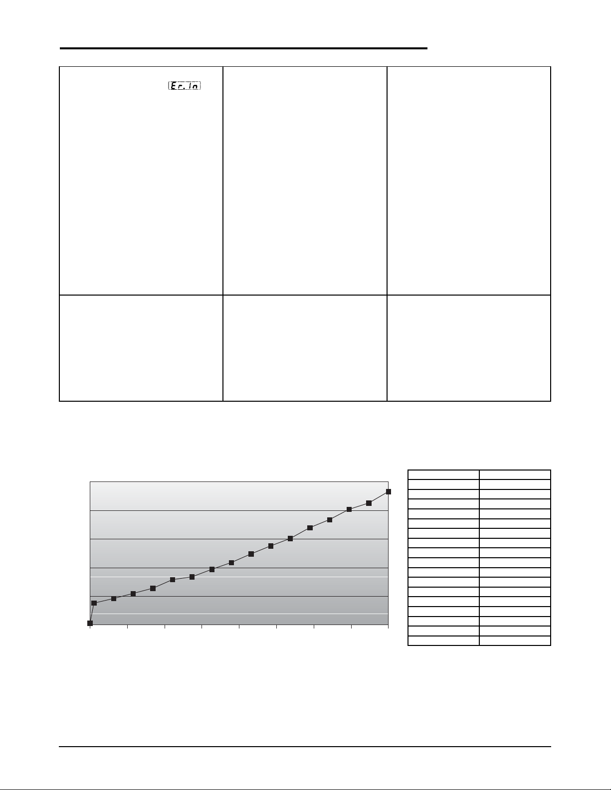
For troubleshooting the thermocouple, use the chart below
Top-Side™ Cooker Probe Chart (Part # 016671)
25.00
20.00
15.00
10.00
5.00
Resistance (Ω Ohm)
0.00
95 125 175 225 275 325 375 425 475
Temperature (°F)
Page 10

8
VI EXPLODED VIEW & PARTS LIST
ORDERING PARTS
Parts may be ordered by part number by calling 1-800-KEATING or your local service company. You may also order
online at Keating’s part store, www.keatingofchicago.com.
Refer to the Keating Top-Side™Cooker Limited Warranty for complete service and ordering information.
The model/serial plate for each cooking head is located on the the control panel assembly. The serial and model
numbers are necessary when ordering.
WARNING AND OPERATING PLATES
All warning and operating plates on the Keating Top-Side™Cooker should be in place at all times. If plates are
damaged or lost, replace them immediately.
MANUAL LIFT TOP-SIDE™COOKER
Figure 6-1
Corresponds with parts list on page 8
To control box
53
15, 18
52
MICRO
LEVELER
effective 2005
Page 11

TOP-SIDE™COOKING HEAD – MANUAL & AUTO-LIFT
Figure 6-1
PART
ITEM DESCRIPTION QTY. NUMBER
1 THERMOSTAT TEMPERATURE PROBE KIT 1 016671
2 COOKING HEAD (COMPLETE) 1 1-800-KEATING
3 STOP CLEVIS PIN, S/S 1 015164
4 SWIVEL BRACKET WIRE SLEEVE (INCL. IN ITEM 5) 1 --5 SWIVEL BRACKET 1 028181
6 SWIVEL BRACKET SUPPORT CLEVIS PIN, S/S 1 015164
7 COOKING SHEET MOUNTING CLIP 2 017316
9 COVER (FOR TSC WITH MICRO LEVELER) 1 1-800-KEATING
10 COOKING SHEET (SINGLE SHEET) 012118
COOKING SHEET (PACKAGE OF 12) 012119
11 MIRACLEAN
®
COOKING FACE PLATE 1 ---
12 HEATING ELEMENT 4KW, 220V (NOT SHOWN) 1 056510
HEATING ELEMENT 480V, 4000W (NOT SHOWN) 1 035664
INSULATION BOARD (NOT SHOWN) 2 016503
13 HIGH LIMIT PROBE 1 015173
14 HIGH LIMIT PROBE MOUNTING PLATE 1 014247
15 KNOB 1 028622
16 COLLAR 2 028486
17 WORM GEAR 1 028487
18
1
/
4-20X
1
/
4" ALLEN SET SCREW 4 028501
19 HOUSING COVER 1 --20 WORM GEAR WHEEL 1 028488
21 SPUR GEAR 2 030241
22 SHAFT 1 028461
23 REAR COVER 1 --24 FRONT HOUSING 1 --25 REAR HOUSING 1 --26 FRONT PLUNGER 1 028521
27 REAR PLUNGER (NOT SHOWN) 1 028522
28 TEFLON WASHER (NOT SHOWN) 1 028490
29 FIBER WASHER (NOT SHOWN) 2 028500
30 TOP-SIDE COOKER WELD. MANUAL 1 052114
31 TOP-SIDE COOKER SPRING SUPPORT WELDMENT 1 052266
32 MANUAL TOP-SIDE GAS SPRING LIFT 1 052251
33 MANUAL TOP-SIDE COOKER GAS SPRING 1 054444
34 SCREW
5
/
16-18 X
3
/
4 HEX HEAD ZINC PLATED 1 015262
35 TOP-SIDE COOKER SUPPORT BRACE GAS 1 052269
36 TOP-SIDE CONDUIT SUPPORT 1 052287
37 NUT RIVET
1
/
4-20 X
5
/
8” 0.332 BODY 1 030269
38 WASHER
1
/
4 ID X
7
/
8 0D X
1
/
16 THK NICKEL 2 015414
39 SCREW
1
/
4-20 X
3
/
4 SERRATED FLANGE LOCK 6 032328
40 TOP-SIDE COOKER LIFT ARM ROD 1 052117
41 U BOLT WITH MOUNTING PLATE 1 052286
42 SCREW 10-24 X
3
/
8 SERRATED FLANGE LOCK 2 032327
43 WASHER 0.190 ID X 0.5630 D X 0.047 THK NICKLE 2 013217
44 MANUAL TOP-SIDE COOKER GAS SPRING ROD 1 052252
45 NUT
1
/
4-20 HEX NICKEL PLATED 1 016383
46
3
/
8-2
1
/
2 CLEVIS PIN 2 015164
47 COTTER KEYS S.S. 2 015166
48
1
/
4-20 X 3” THREADED ROD 2 014226
49
1
/
4” STAR WASHER 4 017046
50
1
/
4-20 ACORN NUT 4 015227
51 WELDMENT HANDLE GEAR GAPPING SYSTEM 1 027311
52 TOPSIDE MICRO LEVELER ASSEMBLY 1 057544
53 TOPSIDE MICRO LEVELER LABEL 1 057432
9
Page 12

10
PART
ITEM DESCRIPTION QTY. NUMBER
1 TOP-SIDE COOKER WELD. AUTO NEW ARM 1 052115
2 AUTO TOP SIDE A0-2 ACTUATOR MTG. 1 053991
3 ACTUATOR AUTO TOPSIDE COOKER 24V 1 060463
4 TOP-SIDE CONDUIT SUPPORT 1 052287
5 TOP-SIDE COOKER LIFT ARM ROD 2 052117
6 TOP-SIDE COOKER HEAD W/ CONDUIT AND CONTROL PANEL 1 --7
3
/8" - 21/2" CLEVIS PIN 1 015164
8 COTTER PIN
5
/16" - 3/8" : 0.72 WIRE 2 015165
9 TOP-SIDE COOKER LIFT ARM ROD 1 052591
AUTO-LIFT TOP-SIDE™COOKER
Figure 6-2
Page 13

11
1. Remove the limit switch black plastic cover on the
actuator.
2. Turn on the power on unit and push the T1, T2 or T3
button on the timer. The actuator will extend the stroke and
lower head. The motor must stop and the stroke should
stop extending before it reaches its mechanical stop. This
movement is controlled by the top micro switch.
3. If the motor fails to stop, manually depress the top
micro switch actuator. Disconnect power to the actuator
motor. Loosen the set screw (2.5mm allen wrench) located
on the top cam. Rotate the top cam clockwise, until the
switch is made (listen for audible click).
4. Tighten the set screw on the cam, using blue locktite.
5. Turn on the power and push the T1, T2 or T3 button on
the timer until it goes to the preset time. The actuator will
retract the stroke and raise the head. The motor must stop
and the stroke should stop retracting before it reaches its
mechanical stop. This movement is controlled by the
bottom micro switch.
6. If the motor fails to stop, manually depress the bottom
micro switch actuator. This will disconnect power to the
actuator motor. Loosen the set screw (2.5mm Allen wrench)
located on the bottom cam. Rotate the bottom cam counter
clockwise until the switch is made (listen for audible click.).
7. Tighten the set screw on the cam, using blue locktite.
8. Test the Top-Side head. Verify the adjustments did not
change the length of the stroke, thus preventing correct
function of the top Top-Side head. The Top-Side cooking
head must be able to reach the griddle plate. If it does not
function properly, complete steps #2 through #7.
9. Reinstall the switch cover.
INSTRUCTIONS FOR MICROSWITCH ADJUSTMENT
AUTO-LIFT TOP-SIDE™ ACTUATOR
Figure 6-3
Page 14

12
TOP-SIDE™COOKER CONTROL PANEL
Figure 6-4
PART
ITEM DESCRIPTION QTY. NUMBER
1 THERMOSTAT 1 056840
THERMOSTAT REPLACEMENT KIT FOR PRE 2005 MODELS 1 057138
2 HI-LIMIT CONTROL 1 010311
3 HI-LIMIT MOUNTING BRACKET 1 016654
4 CONTACTOR, 50A, 3 POLE 1 011184
5 ROCKER SWITCH, LIGHTED, ON/OFF 1 016689
6 INSTRUCTION PLATE ON/OFF SWITCH PLATE 1 016672
7 INDICATING LIGHT, ELEMENT ON, RED 250V 1 036933
INDICATING LIGHT, ROUND RED 220V (Effective 8/31/10) 1 002495
8 INSTRUCTION PLATE ELEMENT ON LIGHT PLATE 1 016673
9 TERMINAL BLOCK 3 POLE 1 002565
10 CORD 9’ 12/3 SJO 1 018480
11 GROUND LUG
1
/
4" 1 028510
12 CONDUIT 65" COMPLETE WITH WIRES 1 034431
13 CONNECTOR
1
/2" LIQUID TIGHT 45° 1 031584
14 CONNECTOR
1
/2" LIQUID TIGHT STRAIGHT 1 031586
15 PLUG 30 AMP 250V 3W 2 POLE 1 020068
Top View with Cover Removed
Front View
To Top-Side Head
15
Page 15
13
TOP-SIDE™COOKER POWER SUPPLY BOX FOR AUTO-LIFT ACTUATORS
WITH DIGITAL TIMER - 120VAC SUPPLY
Figure 6-5
PART
ITEM DESCRIPTION QTY. NUMBER
1 TRANSFORMER STEPDOWN 24VAC 75VA 1 056037
2 RELAY DPDT 24VAC 1 030844
3 RECTIFIER 24VDC 1 018321
4 CIRCUIT BREAKER 3A 1 POLE 250V 1 053338
5 CORD POWER 6’ 1 033559
WIRING DIAGRAM
1
4
3
2
5
Page 16

14
TOP-SIDE™COOKER POWER SUPPLY BOX FOR AUTO-LIFT ACTUATORS
WITH DIGITAL TIMER - 240VAC SUPPLY
Figure 6-6
PART
ITEM DESCRIPTION QTY. NUMBER
1 TRANSFORMER STEPDOWN 24VAC 75VA 1 056037
2 RELAY DPDT 24VAC 1 030844
3 RECTIFIER 24VDC 1 018321
4 CIRCUIT BREAKER 3A 1 POLE 250V 1 053338
5 CORD POWER 9’ 220V 1 020833
WIRING DIAGRAM
1
4
3
2
5
Page 17

15
VII WIRING DIAGRAM
TOP-SIDE™COOKER MANUAL LIFT WIRING DIAGRAM
Figure 6-7
LIGHTED ROCKER
ON/OFF SWITCH
GREEN LIGHT
ON TOP
LIGHTED ROCKER
ON/OFF SWITCH
GREEN LIGHT
ON BOTTOM
OR
NOTE: ANGLED TERMINALS OF SWITCH ARE ALWAYS
TOWARD CONTROL PANEL BOTTOM.
Page 18

16
NOTES:
2. ALL OTHER WIRES ARE 18 AWG.
1. = 12 AWG WIRE.
RD - RED
GR - GREEN
WIRE COLOR CODES:
OR - ORANGE
WH - WHITE
BL - BLACK
GY - GRAY
BR - BROWN
BU - BLUE
COMPONENT CODES:
CR - CONTACTOR 220/240VAC
EO - “ELEMENT ON” LIGHT (RED)
TB - TERMINAL BLOCK
OF - “ON/OFF” SWITCH, LIGHTED (GREEN)
TH - THERMOSTAT
HL - HIGH LIMIT
GRD - GROUNDING LUG
TR - TRANSFORMER
CB - CIRCUIT BEAKER
BR - BRIDGE RECTIFIER
R - RELAY
TOP-SIDE™COOKER AUTO-LIFT WIRING DIAGRAM FOR GAS GRIDDLE
Figure 6-8
Page 19

17
TOP-SIDE™COOKER AUTO-LIFT WIRING DIAGRAM FOR ELECTRIC
GRIDDLE 208 - 240VOLT
Figure 6-9
Page 20

18
TOP-SIDE™COOKER AUTO-LIFT WIRING DIAGRAM FOR ELECTRIC
GRIDDLE 480VOLT
Figure 6-10
Page 21
Page 22

20
SERVICE INFORMATION
If you have a service related question call 1-800-KEATING.
Please state the nature of the call; it will ensure speaking with the appropriate person.
Have your serial and model number available when ordering parts.
KEATING OF CHICAGO, INC.
8901 W. 50th Street, McCook, Illinois 60525-6001
Phone: (708) 246-3000 FAX: (708) 246-3100
Toll Free 1-800-KEATING (In U.S. and Canada)
www .keatingofchicago.com
*As continuous product improvement occurs, specifications may be changed without notice.
KEATING LIMITED WARRANTY CARD
PLEASE COMPLETE AND MAIL AT ONCE–WARRANTY IS NOT IN EFFECT UNTIL CARD IS RETURNED.
WARRANTY CARD IS ALSO AVAILABLE TO COMPLETE ON LINE AT YOUR CONVENIENCE.
COMPANY: __________________________________________________________________________________________________________________
ADDRESS: __________________________________________________________________________________________________________________
CITY: ______________________________________________________________________________ STATE: ________________ ZI P: ____________
DEALER: ____________________________________________________________________________________________________________________
DATE OF PURCHASE: ________________________________________________________________ INVOICE NUMBER: ____________________
SERIAL NUMBER: ________________________________________ FRYER FILTER SYSTE M GRIDDLE
REMAR KS: ______________________________________________ TOP-SIDE COOKER HOT PLATE PASTA PLUS
I HAVE READ THE INSTALLATION AND OPERATION INSTRUCTIONS.
SIGN ED: ____________________________________________________________________________________ DATE:__________________________
“Serving Those Who Serve The Very Best”
®
 Loading...