

Keating SERIES 2009 Operation Manual

Users Manual
CUSTOM PASTA SYSTEM®GAS
SERIES 2009
READ AND SAVE THIS MANUAL FOR FUTURE REFERENCE.
RECORD THE MODEL AND SERIAL
NUMBERS OF THIS CUSTOM PASTA
SYSTE M® IN THE SPACES PROVIDED.
SERIAL NO. ______________________________
MODEL NO. _____________________________
KEEP THESE NUMBERS FOR FUTURE RE FERENCE.
IMPORTANT: Keep a copy of your bill of sale. The date on the bill establishes the warranty period
should service be required. If service is performed, it is in your interest to obtain and keep all receipts.
®
Keating Custom Pasta Systems
are not intended for household use.
This Owner’s Guide provides specific operating and service instructions for your model. Use the
Custom Pasta Systems
®
only as instructed in this Service Manual.
CONTENTS:
SECTION I: INTRODUCTION
GENERAL . . . . . . . . . . . . . . . . . . . . . . . . . . . . . . . . . . . . . . . . . . . . . . .1
STAN DARD FEATURES . . . . . . . . . . . . . . . . . . . . . . . . . . . . . . . . . . . .1
MODEL VARIATIONS . . . . . . . . . . . . . . . . . . . . . . . . . . . . . . . . . . . . . .1
SAFETY PRECAUTIONS . . . . . . . . . . . . . . . . . . . . . . . . . . . . . . . . .1-3
SECTION II: INSTALLATION
DAMAGE DURING SHIPMENT . . . . . . . . . . . . . . . . . . . . . . . . . . . . .3
DROP-IN CUTOUT/INSTALLATION . . . . . . . . . . . . . . . . . . . . . . . . . .3
POSITIONING . . . . . . . . . . . . . . . . . . . . . . . . . . . . . . . . . . . . . . . . . . . .4
LEVELING . . . . . . . . . . . . . . . . . . . . . . . . . . . . . . . . . . . . . . . . . . . . . . .4
RESTRAINING DEVICES . . . . . . . . . . . . . . . . . . . . . . . . . . . . . . . . . .4
SPECIFICATIONS . . . . . . . . . . . . . . . . . . . . . . . . . . . . . . . . . . . . . . . . .5
ELECTRICAL CONNECTION . . . . . . . . . . . . . . . . . . . . . . . . . . . . . . .6
GAS LEAK TESTING . . . . . . . . . . . . . . . . . . . . . . . . . . . . . . . . . . . . . .6
CHECK GAS SUPPLY PRESSURE . . . . . . . . . . . . . . . . . . . . . . . . . .6
SPECIAL NOTICES . . . . . . . . . . . . . . . . . . . . . . . . . . . . . . . . . . . . . . .6
CALIBRATION . . . . . . . . . . . . . . . . . . . . . . . . . . . . . . . . . . . . . . . . . . . .7
WATE R AND DRAIN CONNECTIONS . . . . . . . . . . . . . . . . . . . . . . .7
SECTION III: OPERATING THE PASTA SYSTEM
FILLING . . . . . . . . . . . . . . . . . . . . . . . . . . . . . . . . . . . . . . . . . . . . . . . . .7
LIGHTING . . . . . . . . . . . . . . . . . . . . . . . . . . . . . . . . . . . . . . . . . . . . . . .7
INDICATING LIGHTS . . . . . . . . . . . . . . . . . . . . . . . . . . . . . . . . . . . . . .8
COOKING . . . . . . . . . . . . . . . . . . . . . . . . . . . . . . . . . . . . . . . . . . . . . . .8
Keep this manual for training new personnel.
SHUTDOWN . . . . . . . . . . . . . . . . . . . . . . . . . . . . . . . . . . . . . . . . . . . . .8
DRAINING . . . . . . . . . . . . . . . . . . . . . . . . . . . . . . . . . . . . . . . . . . . . . . .9
CLEANING . . . . . . . . . . . . . . . . . . . . . . . . . . . . . . . . . . . . . . . . . . . . . . .9
ELECTRONIC TIMERS . . . . . . . . . . . . . . . . . . . . . . . . . . . . . . . . .9-10
SECTION IV: MAINTENANCE
WARRANTY REPAIRS . . . . . . . . . . . . . . . . . . . . . . . . . . . . . . . . . . . .10
PREVENTIVE MAINTENANCE . . . . . . . . . . . . . . . . . . . . . . . . . . . . .11
CALIBRATION . . . . . . . . . . . . . . . . . . . . . . . . . . . . . . . . . . . . . . . . . . .12
SECTION V: SERVICE DIAGNOSIS
WATE R FILL AND SAFETY SH UT-OFF CIRCUIT BOARD
AND SENSOR CHECK . . . . . . . . . . . . . . . . . . . . . . . . . . . . . . . .11-12
GENERAL . . . . . . . . . . . . . . . . . . . . . . . . . . . . . . . . . . . . . . . . . . . . . .12
TROUBLE SHOOTING CHART . . . . . . . . . . . . . . . . . . . . . . . . .13-16
REPLACEMENT OF A & B BOARDS . . . . . . . . . . . . . . . . . . . . . . .17
SECTION VI: PARTS LIST
ORDERING PARTS . . . . . . . . . . . . . . . . . . . . . . . . . . . . . . . . . . . . . .18
CONTROL PANEL ASSEMBLY . . . . . . . . . . . . . . . . . . . . . . . . .18-19
GAS PASTA SYSTEM ASSEMBLY I . . . . . . . . . . . . . . . . . . . . . . . . .20
GAS PASTA SYSTEM ASSEMBLY II . . . . . . . . . . . . . . . . . . . . . . . .21
BASKET LIFT POWER SUPPLY BOX . . . . . . . . . . . . . . . . . . . . . . .22
SECTION VII: WIRING DIAGRAMS
PASTA SYSTEM . . . . . . . . . . . . . . . . . . . . . . . . . . . . . . . . . . . . . . . . . .23
AUTO-LIFT GAS PASTA SYSTEM . . . . . . . . . . . . . . . . . . . . . . . .24-28
part# 018766
1-800-KEATING
www.keatingofchicago.com
gasPasta
03/11
This operating, installation, and service manual should be given to
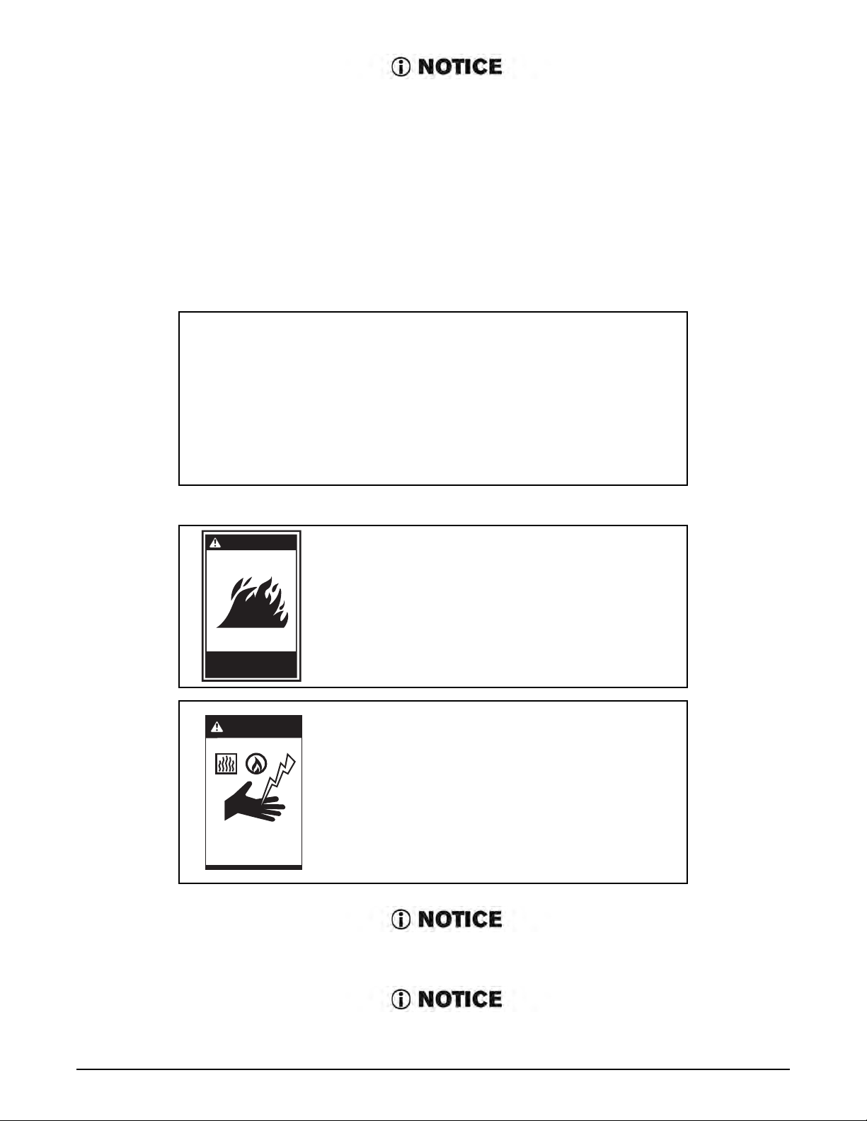
WARNING
Improper installation
can cause damage,
injury or death.
ShockBurnsGas
the user. The operator of the Pasta System should be familiar with
the functions and operation of the cooker. This manual must be kept
in a prominent, easily reachable location near the Pasta System.
POST THIS LABEL IN A
PROM INENT LOCATION ON
YOUR UNIT
IMPORTANT
IN THE EVENT A GAS ODOR IS DETECTED, SHUT
DOWN UNITS AT MAIN SHUT OFF VALVE AND
CONTACT THE LOCAL GAS COMPANY OR GAS
SUPPLIER FOR SERVICE.
WARNING
FOR YOUR SAFETY
DO NOT STORE OR USE GASOLINE OR
OTHER FLAMMABLE VAPORS AND
LIQUIDS IN THE VICINITY OF THIS OR
Do not store flammable
liquids near this or any
other appliance.
Using any parts other than genuine, Keating of Chicago, Inc. factory manufactured part
ANY OTHER APPLIANCE.
IMPROPER INSTALLATION, ADJUSTMENT,
ALTERATION, SERVICE OR MAINTENANCE
CAN CAUSE PROPERTY DAMAGE, INJURY
OR DEATH. READ THE INSTALLATION,
OPERATING AND MAINTENANCE
INSTRUCTIONS THOROUGHLY BEFORE
INSTALLING OR SERVICING THIS
EQUIPMENT.
relieves the manufacturer of all warranty and liability.
Keating of Chicago, Inc. (manufacturer reserves the right to change specifications at
any time.
i

I INTRODUCTION
Instructions in this manual should be read thoroughly
before attempting to operate this Keating Gas Pasta
Cooker. All installation and service on Keating
equipment must be performed by qualified, certified,
licensed and/or authorized installation or service
personnel.
Operating information for Keating equipment has been
prepared for use by qualified and/or authorized
personnel.
Keating equipment is made in the U.S.A. and has
American sizes of hardware. All metric conversions are
approximate.
GENERAL
Keating Pasta Gas Systems are designed to give
maximum production efficiency, delivering high quality
food products. The following design features are
incorporated in Keating Pasta Gas Systems.
STANDARD PASTA SYSTEMS
Sizes: 14 to 24
Water capacity 5-1/2 to 19 gallons
24 Pasta System can cook 6 lbs. of dry pasta per
load up to 110 lbs. per hour
ETL Certified
ETL Santitation Certified
NSF Certified
MODEL VARIATIONS
Basket-Lift Model: Basket-Lift Model Pasta Systems
come with all the same features as the standard
models. The Basket-Lift mechanism lowers the baskets
of food into the water when the timer button is pressed
and raises the baskets when the cooking cycle is
complete. Split baskets are required for these models.
SAFETY
PRECAUTIONS
STANDARD FEATURES
Highly polished stainless steel vessel
Highly polished stainless steel front
Highly polished stainless steel heat transfer tubes
Highly polished stainless steel thermostat bulb
Highly polished stainless steel Hi-Limit sensor
Grid screen over heat transfer tubes
Automatic water fill with manual override
Water solenoid and indicating light
Starch overflow
Two electronic timers
Low water safety shutoff
1” full port front drain valve on 14;
1-1/4” for 18 and larger
High temperature limit control with manual reset
Patented accurate temperature control system ±2°F
Ideal 35” working height
100% safety pilot shut off
3/4” gas connection on single Pasta System
One pair of split baskets or one bulk basket
Patented dual thermostat system
Indicating lights for pilot and secondary thermostat
on
THIS SYMBOL WARNS YOU THAT SERIOUS BURNS
OR OTHER INJURIES MAY RESULT IF SAFETY
INSTRUCTIONS ARE NOT FOLLOWED.
KEATING PASTA SYSTEMS ARE NOT INTENDED FOR
USE WITH COOKING OIL.
This service manual should be retained in a safe
place for future reference. The installation of your
new Pasta System must conform to local codes or
in the absence of local codes, with the current
National Fuel Gas Code ANSI Z223.1/NFPA 54,
(latest edition) Natural Gas Installation
Code CAN/CGA-B149.1 or Propane Installation
Code CAN/CGA-B149.2.
Your ventilation hood, when installed, must
conform to the current ANSI/NFPA 96 (latest
edition).
No frame or restriction shall be constructed around
the Pasta System that will restrict air movement
into the Pasta System’s combustion area or
prevent proper ventilation.
Keating Pasta Systems are designed to operate on
the gas fuel specified on the serial plate and must
not be operated with another gas fuel. They
cannot be converted to another gas fuel by turning
or engaging a switch.
STANDARD ACCESSORIES
Keating Klenzer Sample
Drain clean out rod
Sensor Cleaning Brush
1
WARNING
FOR YOUR SAFETY: Do not store
or use gasoline or other flammable
vapors and liquids in the vicinity of
this or any appliance.
You will post, in a prominent
location, instructions to be followed
Do not store flammable
liquids near this or any
other appliance.
in the event the user smells gas.
This information shall be obtained
from your local gas supplier. You
may use the yellow stick-on label temporarily until you
receive the data from your local gas supplier.
IMPORTANT: In the event a gas odor is detected, shut
down unit at main shut-off valve and contact the local
gas company or gas supplier for emergency service.
exposing any individual to a chemical known to the
State of California to cause cancer or reproductive
toxicity without first giving clear and reasonable
warning to such individuals.” The Governor’s Scientific
Advisory Panel added carbon monoxide
to the list of
hazardous chemicals known to cause reproductive
harm.
In order to establish full compliance with Proposition
65, we attached a yellow warning label to each gas
fired Pasta System manufactured by Keating of
Chicago, Inc.
Carbon monoxide would not be present in
concentrations that would pose a “significant risk” to
the consumer when the equipment is installed,
operated and maintained as follows:
You must maintain this appliance free and clear
from combustibles.
You must maintain the following minimum
clearances from combustible and noncombustible
construction:
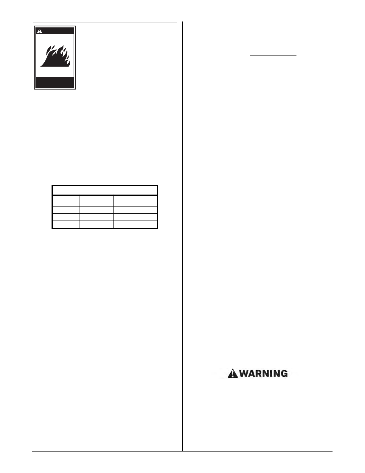
CLEARANCES
Combustible
Construction
Back 6" 0"
Right Side 6" 0"
Left Side 6" 0"
Adequate clearance for servicing and proper
operation must be maintained. Your Pasta System
is designed to be serviced from the front.
Keating commercial Pasta Systems are intended
for other than household use.
ALWAYS instruct new employees on proper Pasta
System operation.
ALWAYS turn Pasta System off each night.
ALWAYS disconnect fuel source before servicing.
NEVER use a Pasta System with cooking oil.
NEVER leave a Pasta System unattended during
operation.
Keating Pasta Systems are NOT intended for use
with cooking oil.
NEVER move a Pasta System with any hot water
in it.
Non-Combustible
Construction
Installed in accordance with all local codes, or in
the absence of local codes, with the current
National Fuel Gas Code A223.1/NFPA54, Natural
Gas Installation CAN/CGA-B149.1 or Propane
Installation Code CAN/CGA-B149.2.
Installed under a properly designed operating
exhaust hood.
Connected to the type of gas for which the
appliance is manufactured.
Pressure regulator is installed in the appliance and
adjusted for the manifold pressure marked on the
serial plate.
If the inlet gas pressure exceeds 6" WC for natural
gas and 12" WC for Propane, an in-line pressure
regulator is required. In-line pressure regulators
are not supplied by Keating. They are to be
provided and installed by others as directed by
local codes.
Adequate air supply to the Pasta System.
The equipment is operated in the manner intended
using the proper utensils.
Keep the equipment clean and have it checked
periodically.
Burner air adjustments, mechanical maintenance
and repairs must be performed by qualified service
personnel.
NEVER introduce objects or liquids into Pasta
System, while operational, which are not designed
or made for cooking.
THIS COOKER MAY NOT BE ALTERED,
MODIFIED OR CHANGED IN ANY WAY.
The State of California enacted the California Safe
drinking water and Toxic Enforcement Act of 1986,
(Prop. 65), which “prohibits any person in the course of
doing business from knowingly and intentionally
If the equipment is not installed, operated and
maintained in accordance with the above,
concentrations of carbon monoxide in excess of
the established limits could be present in the
kitchen environment.
ALL PERSONNEL IN THE WORK PLACE WHO MAY
BE SUBJECT TO ANY EXPOSURE OF CARBON
MONOXIDE MUST BE WARNED OF SUCH
POSSIBLE EXPOSURE. THIS WARNING SHOULD
2
BE CONVEYED IN A MANNER SO THAT IT IS
WARNING
Improper installation
can cause damage,
injury or death.
ShockBurnsGas
CLEARLY UNDERSTOOD BY THE EMPLOYEE, AND
THE EMPLOYEE SHOULD BE ASKED IF IN FACT HE
OR SHE UNDERSTANDS THE CORRECT METHOD
OF OPERATION OF THE EQUIPMENT AND THAT A
RISK OF EXPOSURE EXISTS IF THE EQUIPMENT IS
OPERATED IMPROPERLY.
IF NOT INSTALLED, OPERATED AND MAINTAINED
IN ACCORDANCE WITH THE MANUFACTURER’S
INSTRUCTIONS, THIS PRODUCT COULD EXPOSE
YOU TO SUBSTANCES IN FUEL OR IN FUEL
COMBUSTION WHICH CAN CAUSE DEATH OR
SERIOUS ILLNESS AND WHICH ARE KNOWN TO
THE STATE OF CALIFORNIA TO CAUSE CANCER,
BIRTH DEFECTS OR OTHER REPRODUCTIVE
HARM.
II INSTALLATION
This Pasta System MUST be installed,
inspected, calibrated and serviced by
qualified and/or certified and/or
licensed service personnel – you may
void your Keating warranty if
installation is not completed per
current local, national and Keating
specifications. Contact your dealer for
assistance.
these instructions carefully, we guarantee our full
support of your claims to protect you against loss from
concealed damage.
VISIBLE LOSS OR DAMAGE
Any external evidence of loss or damage must be noted
on the freight bill or express receipt, and signed by the
carrier’s agent. Failure to adequately describe such
external evidence of loss or damage may result in the
carrier refusing to honor a damage claim. The form
required to file such a claim will be supplied by the
carrier.
DO NOT RETURN DAMAGED MERCHANDISE TO
KEATING. FILE YOUR CLAIM AS ABOVE.
INSTALLATION
Installation must conform with local codes or, in
absence of local codes, with the current National Fuel
Gas Code Z223.1/NFPA 54, Natural Gas Installation
CAN/CGA - B149.1 or Propane Installation Code
CAN/CGA-B149.2.
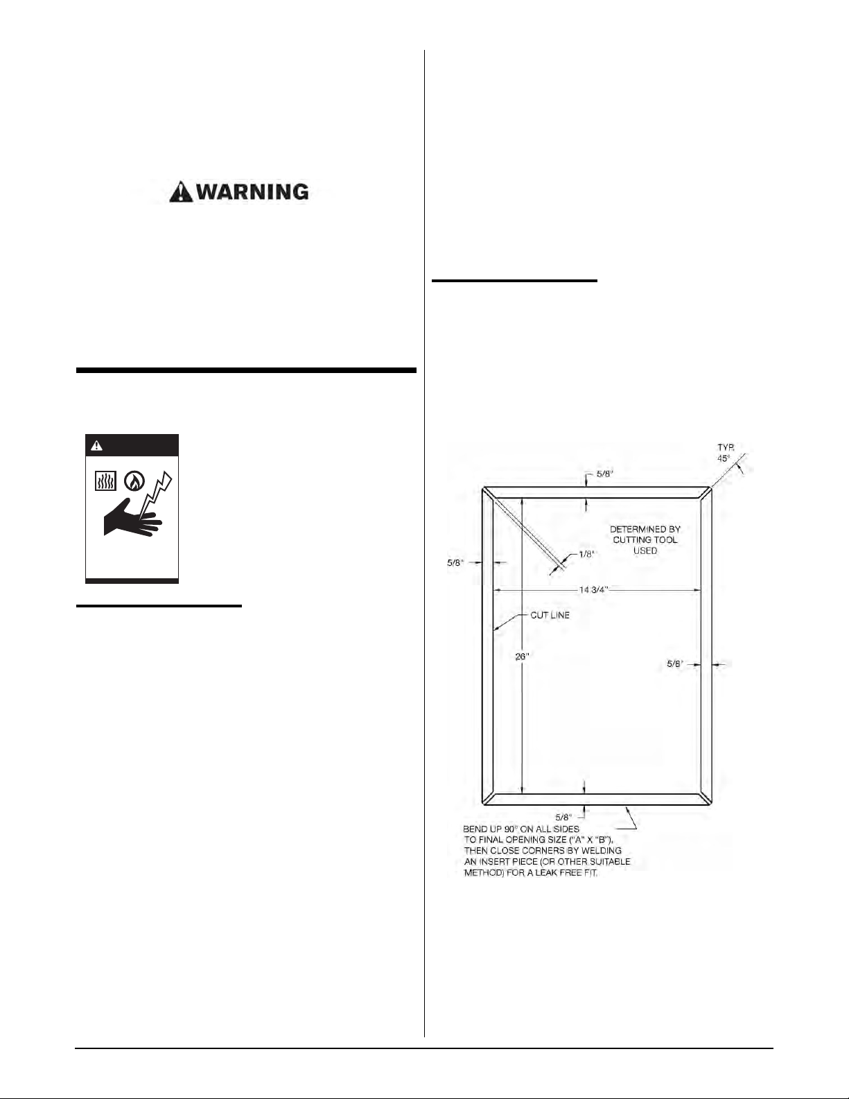
DROP-IN PASTA COUNTER
CUTOUT/INSTALLATION
DAMAGE DURING
SHIPMENT
The Pasta System has been assembled, tested and
inspected at the factory. Upon arrival, the complete
Pasta System should be checked for any damage that
may have occurred during shipment.
IF EQUIPMENT ARRIVES DAMAGED
Keating does not assume responsibility for loss or
damage incurred in transit.
IMPORTANT
This merchandise has been thoroughly inspected and
carefully packed before leaving our plant. Responsibility
for its safe delivery was assumed by the carrier at the
time of shipment. Claims for loss or damage to the
contents should, therefore, be made upon the carrier, as
follows:
CONCEALED LOSS OR DAMAGE
Concealed loss or damage means loss or damage
which does not become apparent until the merchandise
has been unpacked. The contents may be damaged in
transit due to rough handling even though the carton
may not show external damage. When the damage is
discovered upon unpacking, make a written request for
inspection by the carrier’s agent within fifteen days of
the delivery date. Then file a claim with the carrier since
such damage is the carrier’s responsibility. By following
INSTALLATION NOTES
1. Minimum of 130 sq. in. unobstructed vent area near
pasta cooker required for combustion.
2. All Drop-In Pasta must be 16” from any open flame.
3. Pasta must be located no more than 5” from counter
top front.
3
4. Cabinet must be reinforced to support full weight of
past in use (pasta, water, food, etc.).
5. Pasta cooker must be properly ventilated and located
under an exhaust hood.
DROPPING THE PASTA COOKER INTO THE
COUNTER TOP
it is only necessary to place the pasta cooker in such a
position that the front edge overlaps the front raised
edge of the opening.
Push the fryer forward as far as it will go holding the
fryer on approximately a 15° angle, and then drop the
rear of the pasta cooker into its proper position lowering
it down gently so you do not deform the table or
equipment stand.
turning the caster in or out. When the desired level is
reached, tighten the jam nut. Adjustments of more than
3/4” are not recommended on any caster. The same
procedure should be followed to level the Pasta System
from front to back.
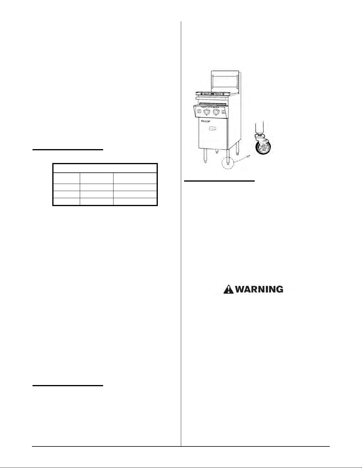
Figure 2-1
POSITIONING
CLEARANCES
Combustible
Construction
Back 6" 0"
Right Side 6" 0"
Left Side 6" 0"
The pasta cooker must be no closer than 6" from any
combustible material. When placed under an exhaust
hood with a fire retardant system it must comply with
ANSI/UL 507-(Latest Edition) and ANSI/NFPA 96(Latest Edition). No frame or restriction can be
constructed around the lower part of the pasta cooker
that would restrict ventilation or air movement into the
pasta cooker. You must insure adequate air supply to
the pasta cooker. ALL connections and placement must
comply with local and national codes. It is the
responsibility of the owner and local installer to comply
with these regulations when installing the Pasta
System.
Adequate clearance for servicing and proper operation
must be maintained. Your pasta cooker is designed to
be serviced from the front. Do not place a pasta cooker
next to a deep fat fryer. Hot oil and water can cause an
unstable condition creating a hazardous situation. The
pasta cooker will operate at highest efficiency when
properly leveled.
Non-Combustible
Construction
Caster
Leg
RESTRAINING
DEVICES
On Pasta System installations with casters, casters and
jam nuts must be completely tightened. Adequate
means must also be provided to limit the movement of
the appliance without depending on the connector, the
quick-disconnect device or its associated piping to limit
the appliance movement.
Connectors must comply with ANSI Z21.69/CAN1
CAN/CGA 6.16 (latest edition) for connectors for
movable gas appliances. Quick-disconnect devices
must comply with ANSI Z21.41/CAN 1 6.9 (or latest
edition) standard for quick-disconnect devices for use
with gas fuel as applicable.
IF DISCONNECTION OF THE RESTRAINT IS
NECESSARY, IT MUST BE RECONNECTED WHEN
THE PASTA SYSTEM IS RETURNED TO ITS
ORIGINALLY INSTALLED POSITION.
Counter model and floor model Pasta System cookers
must be restrained to prevent tipping when installed
in order to avoid splashing, spilling, etc. of hot liquid.
The restraining method may be a manner of installation
or by separate means.
LEVELING
The Pasta System will operate at its highest efficiency
when properly leveled. Place a level on Pasta System
vessel from side to side. For Pasta Systems on legs, the
bottom foot of the leg is adjustable. Turn counter
clockwise to increase height or clockwise to decrease
height until level. For Pasta Systems on casters, the
casters are adjustable by loosening the jam nut and
4
SPECIFICATIONS
Models
14 CUSTOM PASTA SYSTEM 3 5.5 gal. 109K 109K
18 CUSTOM PASTA SYSTEM 4 8.5 gal. 135K 90K
20 CUSTOM PASTA SYSTEM 4 13.5 gal. 135K 90K
24 CUSTOM PASTA SYSTEM 5 19.0 gal. 165K 145K 1" 1" 1" 1" 1"
Total No.
of Burners
Water
Capacity
Fuel Input
(BTU/hr)**
Natural Gas
Propane (LP)
Gas
Single Pasta System Supply Pipe Sizes
(For various pipe lengths)
6' 12' 18' 24' 30'
3
/4"3/4"3/4" 1" 1"
3
/4"3/4"
3
/4"3/4"
1" 1" 1"
1" 1" 1"
NOTE: The pipe size table shown is predicated on
the fact that this is the sole supply line for a single
Pasta System. If multiple Pasta Systems are to be
connected, consult your local gas utility for the proper
gas pipe size.
NOTE: Fuel ratings for propane gas Pasta System
cookers in the U.S. may differ from natural gas models.
In Canada, propane ratings are the same as U.S.
natural gas ratings.
NOTE: Roughly half of all service calls result from
inadequate gas supply. Do not use pipe sizes smaller
than recommended in the table above.
GAS CONNECTION
HAVE YOUR PLUMBER OR GAS COMPANY
CHECK FOR LEAKS.
PIPE JOINT COMPOUNDS RESISTANT TO
PROPANE GASES MUST BE USED.
BEFORE OPERATING THIS PASTA SYSTEM,
CHECK PIPE JOINTS FOR LEAKS BY USING A
SOAP AND WATER SOLUTION OR SNIFFER
ONLY. DO NOT USE AN OPEN FLAME!
WARNING
FOR YOUR SAFETY: Do not store or
use gasoline or other flammable vapors
and liquids in the vicinity of this or any
other appliance.
You will post, in a prominent location,
instructions to be followed in the event
Do not store flammable
liquids near this or any
other appliance.
the user smells gas. This information
shall be obtained from your local gas
supplier.
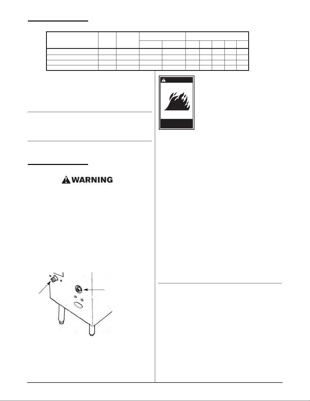
Connect the Pasta System to the main gas supply line at
the rear of the Pasta System. See figure 2-3 above.
The piping should be a minimum of 3/4" NPT supply pipe
for a single Pasta System at the burner manifold. Batteries
require larger supply lines. Installation must conform with
local codes, or in the absence of local codes, with the
current National Fuel Gas Code ANSI Z223.1/NFPA 54,
Natural Gas Installation Code CAN/CGA-B149.1 or
Propane Installation Code CAN/CGA-B149.2.
A3/4" IPS manual gas valve is shipped with each single
Pasta System for field installation. Batteries have a
factory installed manual gas valve for each Pasta
System. The required gas pressure for proper operation
of each Pasta System is 4" water column (WC) for natural
gas and 10” water column (WC) for Propane gas at the
burner manifold. Remove the allen head test plug on the
gas valve and using a manometer to check pressure.
Figure 2-3
Main Gas and Water Supply Connection
Gas
Supply
Water
Supply
If the inlet gas pressure exceeds 7" WC for natural
gas and 11" WC for Propane, an in-line pressure
regulator is required. In-line pressure regulators are
not supplied by Keating. They are to be provided
and installed by others as directed by local codes.
NOTE: If more than one gas Pasta System is on the
same supply line, you may require a larger line. Consult
your local gas company to assure adequate volume and
pressure. Refer to serial plate for proper gas
requirements for your particular model.
5
ELECTRICAL
CONNECTION
WARNING
The Keating Custom Pasta Gas
System is equipped with a 9'
neoprene covered, 3 wire electrical
cord with a three-pronged grounded
plug for protection against electrical
shock. This plug must be placed into a
Plug into a
properly grounded
three-prong receptacle.
120V properly grounded
three-pronged outlet (NEMA 5-15 or 5-
20). For proper grounding procedures
see local codes or, in the absence of
local codes, the current National Electrical Code
ANSI/NFPA 70 or Canadian Electrical Code CAN 22.2
as applicable.
NOTE: The electrical wiring diagram for the Pasta
System is attached to the inside of the Pasta System
door. Some of the more common versions are included
in the back of this manual.
CHECK GAS SUPPLY
PRESSURE
Special attention should be given to the supply pressure
and gas flow pressure at the supply connection to the
Pasta System. The nominal gas should be 4" WC for
natural gas and 10" WC for propane gas.
If the supply pressure is lower or higher than the rated
(nominal) pressure, then the reason should be investigated
and the gas supplier contacted.
If the supply is lower than 2 1/2" WC or higher than 7" WC
for natural gas or lower then 9” WC or higher than 12" WC
for propane gas, then the Pasta System should be shut
down and a service company or supplier notified. No
adjustments should be made and the Pasta System should
not be operated.
ONLY BY CERTIFIED PROFESSIONAL
1. Turn off main gas supply valve.
2. Remove pressure measuring stud screw located at
the “out-flow” (closest to gas burner) of the gas
valve and attach a manometer.
DO NOT CUT OR REMOVE THE GROUNDING
PRONG FROM THIS PLUG.
GAS LEAK TESTING
Prior to lighting your Pasta System:
1. Make sure all thermostats, switches and safety
valves are in the “OFF” position.
2. Turn main supply gas cock (Item 18, page 20) to
the “ON” position.
3. Have your plumber or gas company check for leaks
with a soap solution or sniffer. (NEVER check with
an open flame)
4. Have your plumber or gas company representative
light the constant pilot. (Not necessary if your Pasta
System has an optional spark ignitor.)
NOTE: It is estimated that half of all service calls
made on Keating Pasta Gas Systems result from an
inadequate gas supply. During installation, have a gas
company representative make certain that the Pasta
System is receiving adequate gas pressure and volume.
PROPANE GAS MAY EVENTUALLY LOSE ITS ODOR
AND PRECAUTIONS SHOULD BE TAKEN TO
ASSURE THAT IT IS NOT PRESENT EVEN THOUGH
YOU DO NOT DETECT AN ODOR. IF THERE IS ANY
DOUBT, YOU SHOULD CALL YOUR LOCAL
PROPANE GAS SUPPLIER FOR ASSISTANCE.
3. Remove cover screw from the gas valve pressure
adjustment valve.
4. Open main gas supply valve and start Pasta
System according to instructions with the
thermostat set at 190°F(87.8°C).
5. Once the Pasta System is in operation, adjust
pressure valve to 4" WC for natural gas and 10” WC
for propane gas.
6. Turn Pasta System off, close main gas supply
valve, remove manometer and tighten cover screw
into pressure measuring stud.
SPECIAL NOTICES
The Pasta System should be operated only in an area that
has good air circulation.
The Pasta System must be installed under an electrically
powered ventilating hood.
The operator should be properly trained to the functioning
of the Pasta System.
This instruction manual should be supplied to the operator.
Constructional changes to the area where the Pasta
System is installed shall not affect the air supply to the
Pasta System. The installation, start-up and changes
required when changing from one gas type to another can
be performed only by a certified professional.
The Pasta System is intended only for commercial use and
is to be operated only by professionals.
It is required that the Pasta System is regularly inspected for
proper function. The frequency of inspections are
dependent of the Pasta System usage, however it should
be performed at least once a day.
After adjustment or service work the Pasta System has to
be checked for gas leaks.
6
NOTE: After conversions, readjustments or service
work, the Pasta System has to be tested for proper
functioning. Basically the following applies:
CALIBRATION
For Calibration refer to page 12 – Calibration. Note:
Calibration is not covered under warranty.
WATER AND DRAIN
CONNECTIONS
The water supply connection, located at the bottom rear of
the Pasta System and marked water inlet, is a standard 3/8"
female pipe connection. The water pressure should be
between 20 - 60 psi. If the pressure exceeds 60 psi, a
pressure regulator must be used. The water temperature
must not exceed 150°F(65.6°C). Hot or warm water is not
needed due to the instant recovery of the Pasta System;
however, it’s use is not detrimental.
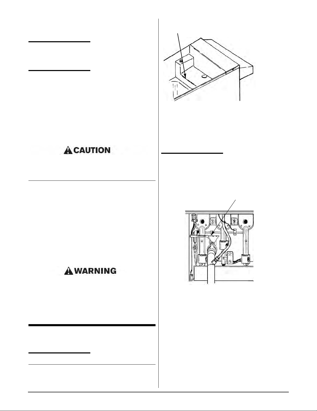
Figure 3-1
Manual Water Fill Level
When the water fill toggle switch (located between the
green and blue indicating lights) is turned on, the Pasta
System vessel automatically will be filled to the proper
level. If the vessel is being manually filled with water
from a faucet or through the manual fill button, fill to just
below the overflow deck. The black manual fill button is
located to the right of the blue water fill indicating light.
Connections suitable for hot water must be used.
All connections must be tested for leaks before
using the Pasta System.
NOTE: For Pasta Systems with casters, flexible hose
must be used to avoid leaking when the Pasta System
is moved for cleaning.
If during operation the boil is killed when water
automatically enters the Pasta System, turn the water
pressure down until water is added without killing the boil.
The drain terminates within inches of the floor and is
designed for the standard dump to drain opening. In most
cases, the health department will not allow a direct
connection between the Pasta System drain and the floor
receptacle. Contact your local health department for
specific information in your area.
IT MAY BE NECESSARY TO INSTALL A BACK FLOW
PROTECTOR OR CHECK VALVE ON THE WATER
SUPPLY LINE TO THE PASTA SYSTEM. CHECK WITH
EITHER YOUR LOCAL WATER OR HEALTH
DEPARTMENT TO DETERMINE IF THIS IS
NECESSARY IN YOUR SPECIFIC AREA.
III OPERATING
FILLING
NOTE: Before filling the Pasta System make certain the
vessel is sanitized, dry and the drain valve is completely
closed.
LIGHTING
In the event of a power failure, check to see if constant
pilot is still burning before resuming operation. If not,
wait five minutes to allow any accumulated gas to
escape and then re-light the constant pilot.
Figure 3-2
Lighting Controls
1. Open the main supply gas cock.
2. Turn “On” main power On/Off switch (located
between the amber and green indicating lights).
3. Light the constant pilot (located next to left burner as
you face it). If your Pasta System has an optional
spark ignitor, omit this step.
4. Activate pilot light momentary switch (left top corner)
and hold about 30 seconds, releasing it after pilot
indicting light is illuminated. If the runner pilot tube
fails to stay lit, wait five minutes before attempting to
relight to allow any accumulated gas to escape.
5. Set the primary (left) thermostat to 212°F(100°C) and
the secondary (right) thermostat to 190°F(87.8°C) or
Constant pilot
location
7
less. Setting the secondary thermostat above
190°F(87.8°C) could allow the Pasta System to boil
over or short cycle.
INDICATING LIGHTS
● Amber–shows the runner pilot is lit.
● Green–shows the secondary (right) thermostat is
calling for heat from the center burner(s).
● Blue–shows water is filling into the Pasta System
vessel through the Pasta System water solenoid valve.
NOTE: The black manual water fill button is located to
the right of the blue indicating light. This may be used to
add water manually by depressing.
A. Standard Pasta System
1. Fill Pasta System as described on page 7 – Filling.
2. Set primary (left) thermostat to 212°F(100°C) and
secondary (right) thermostat to 190°F(87.8°C).
3. When the water starts boiling, lower baskets slowly
into the hot water.
4. Set timer for left or right side basket, whichever is
being lowered into water.
5. When timer sounds, lift basket out of water. Place
on basket hanger rods on splashback of Pasta
System to allow draining of excess water.
B. Basket-Lift Model
COOKING
Keating Pasta Gas Systems are designed to provide
maximum production efficiency and deliver high quality
food products. Low-temperature cooking and highly
polished stainless steel mean greater energy savings. Two
thermostats are used to provide instant recovery and to
save energy while water is boiling. The secondary (right)
thermostat calls for additional heat at start up or
occasionally when water is added. Follow cooking
procedures below for your model.
NOTE: Use of sodium chloride (salt) during the
cooking process will have a detrimental effect on the
cooker tank and will void the warranty.
OPERATION OF THIS PASTA SYSTEM SHOULD
BE LIMITED TO PERSONNEL WHO HAVE BEEN
THOROUGHLY TRAINED IN OPERATING
PROCEDURES.
USE ONLY KEATING APPROVED BASKETS IN
YOUR PASTA SYSTEM. NEVER OVERFILL
BASKETS. DO NOT BANG BASKETS ON
BASKET HANGERS OR PASTA SYSTEM
VESSEL.
1. Fill Pasta System as described on page 7 – Filling.
2. Set primary (left) thermostat to 212°F(100°C) and
secondary (right) thermostat to 190°F(87.8°C).
3. Fill basket(s) to proper level and place on upper
basket hanger rods on splashback of Pasta
System.
4. Set timers to desired cooking time using T1, T2 or
T3. (For Programming Timers see page 9-10 for 14”
BL models & 10 for all others).
5. Push Start/Stop or T1, T2, or T3 button on timer(s).
Basket(s) will automatically lower into the Pasta
System vessel.
6. When cooking cycle is complete, an audible alarm
will sound and the basket(s) will raise automatically.
Allow water to drain before removing.
SHUTDOWN
1. Turn main power On/Off switch to “OFF” position.
2. Turn gas supply valve to “OFF” position.
3. Check to make sure all burners and pilots are
extinguished.
CARE SHOULD BE TAKEN WHEN LOWERING
BASKETS INTO PASTA SYSTEM TO PREVENT
SPLASHING HOT WATER FROM PASTA
SYSTEM VESSEL.
NEVER LIFT BASKETS DIRECTLY OUT OF THE
PASTA SYSTEM VESSEL WITHOUT DRAINING
AS SEVERE INJURY MAY RESULT.
NOTE: For counter model Pasta Systems, always
check the rear drain operating handle before attempting
to use the Pasta System. A safety switch prevents the
Pasta System from operating if the handle is not pushed
in completely and latched.
8
 Loading...