


200mm
688mm
90mm
Centre of Gravity
96mm
814mm
Page. 1
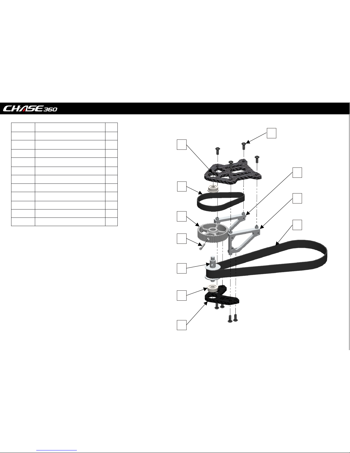
1
Main belt (147MXL-9MM)
Lower motor block
18T 2nd Stage pinion
1ST Stage pulley pin
Page. 2
2
3
4
5
6
7
8
9
10
11
ITEM NO.
DESCRIP TION
QTY.
1 1
2
8
3 1
4
1
5
1
6 1
7
2
8
9
10
11
1
1
1
1
Round head screw(M2.5 x 6)
Bearing (4x10x4)
Motor mount bracket right
Motor mount bracket left
Upper motor block
50T Pulley
1ST Stage belt (63MXL-6mm)

0.5mm MIN
0.5mm MIN
Turn the motor over by hand to test belt positioning.
Adjust the motor pinion height until the belt runs
central on the front pulley
Make sure your motor has
a flat ground on the shaft
for the pinion grub screw.
This step can be completed at any time.
But is easier before installing the 1st stage assembly into the model
2
1
3
4
Set Screw (M3)
Flat head screw M3X6
Motor(1880KV)
pinion 1 8T (1 9T )
1
2
1
1
ITEM NO
DESCRIP TION QTY.
1
2
3
4
Page. 3
tip : the pinion should be positioned as
close as possible to the top plate
to avoid rubbing and correct belt
alignment

Bearing (3x7x3)
Belt guide pulley
spacin g wa sh er
Page. 4
GYRO TRAY
Boom Clamp
STEP 4
1
2
4
6
3
7
1
2
3
4
5
ITEM NO.
DESCRIP TION
QTY.
1 1
2
4
3 2
4
2
5
1
6 4
7
2
ITEM NO.
DESCRIP TION
QTY.
1 1
2
4
3 2
4
2
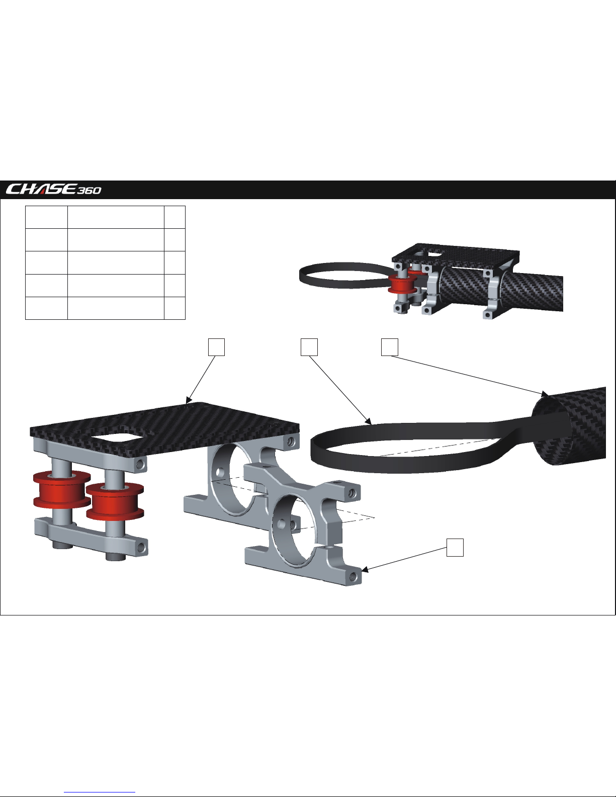
CAP Screw (M3 x 24)
UP Pulley holder SET
Spacer sleeve
Down Pulley holder SET
Flat head screw M2.5X6

15mm Nominal
Tip - It is best to position the servo arms on servos
(with 0 trim) closest to level during this step
.
6
4
Long side of the
brackets face
clockwise.
CYCLIC SERVO
Lock Nut (M2)
UPPER BEARING BLOCK
Bearing (8x16x5)
SERVO MOUNT
LOWER BEARING BLOCK
Page. 5
1
2
3
4 5 6 7
1
2
ITEM NO.
DESCRIP TION
QTY.
1 6
2
3
3 6
4
6
5
4
6 1
7
3
ITEM NO.
DESCRIP TION
QTY.
1 1
2
1
Round head screw (M2 x 6)
Round head screw (M2.5 x 6)
Bearing (8x16x5)
Power the servo to adjust the central
point at l ev el c on dition before ass em bl e

Recommended lipo 1200 - 1400 mah.
Size restrictions 39mm x 45mm x 116mm.
Or unlimited length with front tail servo
mount option (Refer to Step 26)
Mirror this step for
Left side frame.
Lipo tra y bu tt on ( right)
Side frame
LIPO 1200 - 1400mAh
Page. 6
1
2
4
3
1
2
4
3
Round head screw (M2 x 4)
ITEM NO
DESCRIP TION QTY.
1 1
2 3
3 1
4 1
canopy locating pin
ITEM NO
DESCRIP TION QTY.
1 1
2 2
3 1
4 1
Flat head screw M2.5X6
Lipo tray
Lipo tray fixed mount

ITEM NO
DESCRIP TION QTY.
1 LANDING GEAR - LEFT 1
2 LANDING GEAR - RIGHT 1
3 LANDING GEAR MOUNT 2
4 FROM STEP 6 1
5 8
Page. 7
lock the screws only after main
frame left is well-assembled.
1234
5
CAP Screw (M2.5 x 8)

FROM STEP 5
1
FROM STEP 2
1
FRAME SPACERS
2
Lipo sliding rail (right)
1
Round head screw (M2 x 4)
2
2
Page. 8
CAP Screw (M2.5 x 6)
5
1
2
3
4
5
ITEM
NO.
DESCRIP TION QTY.
1
2
3
4
5
6
7
6
7
CAP Screw (M2.5 x 8)
8
Frame Washer (Red)
7
8

1
2
4
3
5
6
Ensure no free play in the
tail shaft by fastening the Locking collar
and pinion against the bearings.
Tail shaft
Tail shaft locking collar
Tail Pinion (15T)
Set Screw (M3x3)
Tail Box
Bearings (4x8x3)
Page. 9
1
1
2
1
1
2
ITEM NO
DESCRIP TION QTY.
1
2
3
4
5
6

Tip: Tighten Screws in a few
stages to ensure the bracket
remains parallel with the tail shaft.
Refer to step 25 for details.
ITEM NO.
DESCRIP TION
QTY.
1
Fin Spacer
1
2
Tail Boom
1
3 2
4
Pitch Slider Bracket
1
5
Tail Belt
1
6 1
7
1
8 1
9
Tail control guide
2
10
1
11 1
Page. 10
11
1 2
345
8
7
6
10
9
12
12 2
CAP Screw (M2 x 10)
CAP Screw (M2 x 4)
CAP Screw (M2 x 6)
CF Vertical stabilizer
Tail boom brace mount
Heat shrink tubing
CAP Screw (ST2 x 6)
ITEM NO. DESCRIP TION QTY.
1 Parts From Step 4 1
2
Tail Belt 1
3 Parts from Step 10 1
4 Boom Clamp 1
Page. 11
1 2 3
4

X2
ITEM NO. DESCRIP TION QTY.
1 Parts From Step 5 1
2
Parts From Step 10
1
3
5
ITEM NO.
DESCRIP TION QTY.
1 Front canopy mounting bolt 1
2
1
Page. 12
1 2 3
1
2
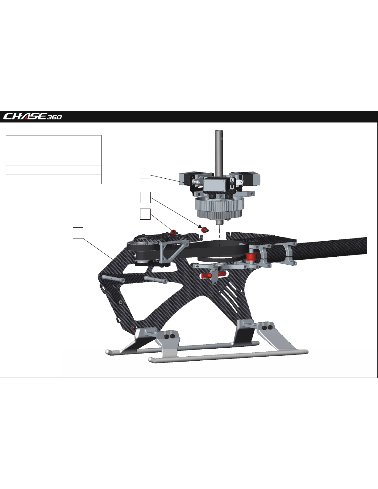
CAP Screw (M2.5 x 6)
Frame Washer (Red)
4
5
4
Set Screw (M2.5x10)

Main shaft is symmetrical with
no top or bottom.
May be installed either way.
ITEM NO. DESCRIP TION QTY.
1 Parts From Step 12 1
2
1
3 1
4 1
5 1
6
1
Page. 13
ITEM NO. DESCRIP TION QTY.
1 Parts From Step 12 1
2
1
3 1
4 1
5 Parts From Step 4 1
6
1
1
2
3
4
5
6
1
2
3
4
5
6
Bearing (8x14x4)
First reduction gear(80T)
Bearing (10x15x4)
Auto-rotation gear (50t)
One way bearing(10x14x6)
CAP Screw (M3 x 24)
Lock Nut (M3)
Washer (8x10x0.5)
Main shaft
Page. 14
ITEM NO. DESCRIP TION QTY.
1 Parts From Step 12 1
2
1
3
2
1
2
3
Parts From Step 12
4
4
2
CAP Screw (M2.5 x 6)
Frame Washer (Red)

Page. 15
1
ITEM NO. DESCRIP TION QTY.
1 1
2
1
3 14
4 12
5 1
6
2
7
8
3
4
5
6
7
8
9
9
2
Set Screw (M2.5x10)
Frame Washer (Red)
Front canopy mounting bolt
CAP Screw (M2.5 x 6)
CAP Screw (M2.5 x 8)
Round head screw (M2 x 4)
1
Lipo sliding rail left
1
CF front electronics board
1
Side frame

note : factory pre-assembled
Page. 16
ITEM NO. DESCRIP TION QTY.
1 1
2
1
3 6
4 1
5 1
6
3
7
1
2
3
4
5
6
7
Oscillating bearing
Swashplate Internal
Linkage ball A
Swashplate Outer ring
Swashplate mounting pin
Round head screw (M2 x 4)
Bearing (20x27x4)
1

1
Page. 17
9.8
10
Larger ID faces
inwards
.
X2
2
3
4
5
6
7
1
2
3
4
Bearings (2x5x2.5)
CAP Screw (M3 x 24)
2
ITEM NO
DESCRIP TION QTY.
1
2
3
4
5
6
7
8
9
10
11
2
ITEM NO
DESCRIP TION QTY.
1
2
3
4
5
6
7
Flybarless linkage arm
Flybarless swashplate control arm
6
5
7
8 9
10
11
8
2
2
2
2
Main rotor holder
Bearings (5x10x4)
Linkage ball A
Round head screw (M2 x 6)
Main rotor branch control arm
2
4
2
4
2
Washer (5x9x0.8)
Damper rubber
2
Main rotor housing
1
Feathering shaft
1
Round head screw (M3 x 6)
Washer (3x8x0.9)
Washer (2x5x0.5)
Thrust bearing (F5-10M)
Washer (5x7x0.5)

Page. 18
X2
43mm
30mm
X3
X2
43mm
X3
ITEM NO. DESCRIP TION QTY.
1 6
2
3
1
ITEM NO. DESCRIP TION QTY.
1 4
2
4
3 2
ITEM NO. DESCRIP TION QTY.
1 1
2
1
2
1
2
1
3
2
Ball link A
Linkage rod (15mm)
Set Screw (M2.5x10)
Ball link B
Linkage rod (15mm)
Lock Nut (M2)
CAP Screw (M3 x 24)

Page. 19
ITEM NO. DESCRIP TION QTY.
1 2
2
1
3 1
4 2
1 2 3 4
Round head screw (M2 x 4)
Anti-rotation bracket
5 2
5
CAP Screw (M2.5 x 6)
Frame Washer (Red)
Anti-rotation bracket mount

Page. 20
23
ITEM NO. DESCRIP TION QTY.
1 2
2
4
3 2
4 2
5 2
ITEM NO. DESCRIP TION QTY.
1 2
2
2
3 2
6
5
4
3
2
1
8
9
7
1
3
2
6
7
8
9
CAP Screw (M2 x 5)
ITEM NO. DESCRIP TION QTY.
2
1
2
2
Bearings (3x6x2.5)
Thrust bearing (F5-10M)
Tail rotor holder
Linkage ball B
Washer (3.1x4.4x0.3)
Washer (2.1x5x0.7)
Flat head screw M2X7
Tail rotor T type holder
CAP Screw (M2 x 12)
Lock Nut (M2)
Tail blade

Page. 21
Note : Factory pre-assembled
ITEM NO. DESCRIP TION QTY.
1 1
2
2
3 4
4 1
5 2
6
2
7
4
1 2 3
5
6
7
8
8
1
1
Tail push bearing mount
Bearings (6x10x3)
E - clip (1.5mm)
T type arm
Ball link for tail holder
Pin
Tail push bearing
Set Screw (M3x3)

9
0
Check that the pitch slider fork is square
to the shaft and the slider does not bind.
loosen bolts and adjust if required.
Page. 22
1
2
3
4
5
6
7
8
9
ITEM NO. DESCRIP TION QTY.
1 2
2
1
3 1
4 1
5 2
ITEM NO. DESCRIP TION QTY.
6 1
7
2
8 1
9 1
Flange Bearing (2x5x2.5)
Lock Nut (M2)
Linkage ball A
CAP Screw (M2 x 4)
Tail rocket arm
Round head screw (M2 x 4)
Washer (2x5x0.5)
CAP Screw (M2 x 14)
Tail control arm

Rear servo mount option. Mini or Micro servo
Front servo mount option. Micro
servo ONLY.
12mm Nominal
The Chase 360 has 2 Tail servo
location options,
At the front, high in the frame for 1.
the lowest moment of inertia and optimal CG.
2. Under the tail boom at the rear of the frame.
Page. 23
ITEM NO. DESCRIP TION QTY.
1 1
2
4
3 2
ITEM NO. DESCRIP TION QTY.
1 4
2
1
3 2
4 1
1
2
3
1
2
3
4
Tail Servo
CAP Screw (ST2 x 6)
Servo Mount
Servo spacer
Round head screw (M2 x 4)
Tail Servo Fixed plate
Tail Servo mount

Page. 24
Screw reserved for boom
brace installation
Build the tail pushrod to suit your desired servo location
For rear mount servo Extension for front mount servo

Note :the boom brace may be mounted in multiple locations.
Page. 25
1 2 3 4 5 6
7
ITEM NO. DESCRIP TION QTY.
1 2
2
4
3
4
4 2
5 1
6
1
7
2
Tail boom brace
Tail boom brace end
Frame Washer (Red)
CAP Screw (M2.5 x 8)
CAP Screw (M2.5 x 6)
Tail boom brace mount
CAP Screw (M2.5 x 10)
 Loading...