

Page 1
“The Right Control for Your Application.”
12095 NW 39 Street, Coral Springs, FL 33065-2516
Telephone: 954-346-4900; Fax: 954-346-3377
KB Electronics, Inc. www.KBelectronics.com
Dynamic Brake Module (Part No. 9598) Installation Instructions
Dynamic Brake Module (Part No. 9598) Installation Instructions
Dynamic Brake Module (Part No. 9598) Installation InstructionsDynamic Brake Module (Part No. 9598) Installation Instructions
Dynamic Brake Module (Part No. 9598) Is Designed for Use with
Dynamic Brake Module (Part No. 9598) Is Designed for Use with
Dynamic Brake Module (Part No. 9598) Is Designed for Use withDynamic Brake Module (Part No. 9598) Is Designed for Use with
KBVF Series Drives: Model Nos. KBVF-21D, 22D, 13, 23, 23D, 14, 24, 24D
KBBL Series Drives: Model Nos. KBBL-2P2D, 2P3D, 2P6D, 21D, 22D, 23D, 24D
SAFETY WARNING! Please read carefully before proceeding.
This product should be installed and serviced by a qualified technician, electrician, or electrical maintenance person familiar with its
operation and the hazards involved. Proper installation, which includes wiring, mounting in proper enclosure, fusing or other current
protection, and grounding can reduce the chance of electrical shocks, fires, or explosion in this product or products used with this product,
such as electric motors, switches, coils, solenoids, and/or relays. Eye protection must be worn and insulated adjustment tools must be
used when working with drive under power. This product is constructed of materials (plastics, metals, carbon, silicon, etc.) which may be a
potential hazard. Proper shielding, grounding, and filtering of this product can reduce the emission of radio frequency interference (RFI)
which may adversely affect sensitive electronic equipment. If further information is required on this product, contact our Sales Department.
The drive contains electronic start/stop circuits which can be used to start and stop the drive. However, these circuits are never to be used
as safety disconnects since they are not fail-safe. Use only the AC line for this purpose.
Be sure to follow all instructions carefully. Fire and/or electrocution can result due to improper use of this product.
It is the responsibility of the equipment manufacturer and individual installer to supply this Safety Warning to the ultimate end user of this
product.
IMPORTANT
The KBVF Series Installation and Operation Manual (Part No. A40288) and the KBBL Series Installation Instructions (Part No. A40152) must
be read and understood before attempting to operate the Dynamic Brake Module.
Items Included in this Package
Dynamic Brake Module, Installation Instructions, Interconnect Wires, Jumper (for KBVF Series Drives only), Warranty Registration Card.
Dynamic Brake Module Rating
Up to 25% continuous braking torque and 200% instantaneous braking torque (maximum 1 HP (0.75 kW)).
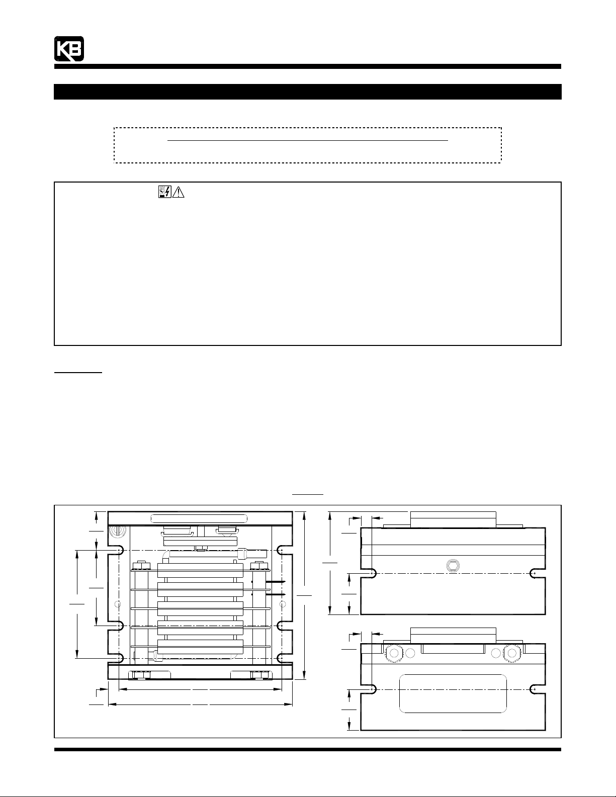
Figure 1
Mechanical Specifications (Inches/mm)
2.50
63.5
0.89
22.6
1.75
44.5
3.88
98.4
2.38
60.4
0.25
6.35
0.95
24.1
0.25
6.35
3.80
0.25
6.35
Recommended Mounting Screw (10 Places): #10
96.5
4.30
109
0.95
24.1
(A40148) – Rev. B – 7/18/2006 – Z4181B00 Page 1 of 4
Page 2
“The Right Control for Your Application.”
KB Electronics, Inc. www.KBelectronics.com
Dynamic Brake Module (Part No. 9598) Installation Instructions
Dynamic Brake Module (Part No. 9598) Installation Instructions
Dynamic Brake Module (Part No. 9598) Installation InstructionsDynamic Brake Module (Part No. 9598) Installation Instructions
1111 DESCRIPTION
DESCRIPTION
DESCRIPTIONDESCRIPTION
The Dynamic Brake Module (DBM) is designed to be used with the KBVF Series Drives (Model Nos. KBVF-21D, 22D, 13, 23, 23D, 14, 24,
24D) and the KBBL Series Drives (Model Nos. KBBL-2P2D, 2P3D, 2P6D, 21D, 22D, 23D, 24D). The DBM provides up to 25% continuous
braking torque and 200% instantaneous braking torque (maximum 1 HP (0.75 kW)).
2222 MOUNTING INSTRUCTIONS
MOUNTING INSTRUCTIONS
MOUNTING INSTRUCTIONSMOUNTING INSTRUCTIONS
WARNING! This DBM must be mounted in an enclosure. Care should be taken to avoid extreme hazardous locations
where physical damage to the DBM can occur due to moisture, metal chips, dust, and other contamination, including corrosive
atmosphere that may be harmful. See Safety Warning, on page 1. Do not use this DBM in an explosion-proof application.
Application Note: The enclosure should be large enough to allow for proper heat dissipation (including additional cooling, if required) so
that the ambient temperature does not exceed 45 °C (113 °F). Leave enough room to allow for any wiring that is required. See Figure 1,
on page 1.
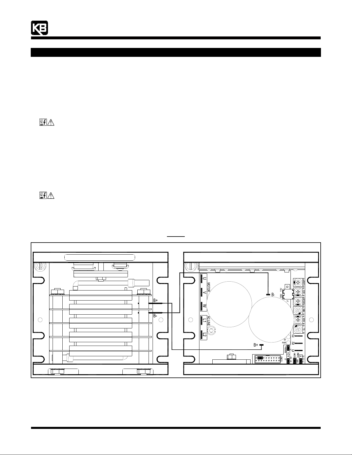
The DBM should be mounted close to the KBVF or KBBL Series Drive, as shown in Figure 2.
3333 WIRING
WIRING
WIRINGWIRING
WARNING! Read Safety Warning, on page 1, before using the drive. Disconnect main power when making connections
to the drive. To avoid electric shock, be sure to properly ground the drive.
12095 NW 39 Street, Coral Springs, FL 33065-2516
Telephone: 954-346-4900; Fax: 954-346-3377
The DBM should be wired to the KBVF or KBBL Series Drive using the 9” 18AWG red/black Interconnect Wires which are provided.
Terminal “B+” on the DBM connects to Terminal “B+” on the KBVF or KBBL Series Drive. Terminal “B-“ on the DBM connects to Terminal
“B-“ on the KBVF or KBBL Series Drive. See Figure 2.
Figure 2
Connection Diagram
Drive*Dynamic Brake Module
*Layout, trimpot settings, and jumper settings may vary slightly.
(A40148) – Rev. B – 7/18/2006 – Z4181B00 Page 2 of 4
Page 3

“The Right Control for Your Application.”
KB Electronics, Inc. www.KBelectronics.com
Dynamic Brake Module (Part No. 9598) Installation Instructions
Dynamic Brake Module (Part No. 9598) Installation Instructions
Dynamic Brake Module (Part No. 9598) Installation InstructionsDynamic Brake Module (Part No. 9598) Installation Instructions
4444 KBVF SERIES DRIVES ONLY
KBVF SERIES DRIVES ONLY
KBVF SERIES DRIVES ONLYKBVF SERIES DRIVES ONLY
In order for the DBM to operate properly with the KBVF Series Drives, the Decel Extend Feature must be disabled. This is accomplished
by installing the jumper (supplied), using long-nose pliers, onto pins 15 and 17 of CON3, as shown in Figure 3.
Disconnect main power when installing this jumper.
When installing the optional SIVFR Signal Isolator and Run/Fault Relay (Part No. 9597) in addition to the Dynamic Brake Module, do not
install the jumper on CON3, shown in Figure 3. The connector will be occupied by the End Connector of the Ribbon Cable which is used
to interface the SIVFR to the KBVF Series Drive. Set Jumper J5, on the SIVFR, to the “DBM” position. See Figure 4.
12095 NW 39 Street, Coral Springs, FL 33065-2516
Telephone: 954-346-4900; Fax: 954-346-3377
Jumper (Supplied) Installed on CON3 Pins 15 and 17
5555 KBBL SERIES DRIVES ONLY
KBBL SERIES DRIVES ONLY
KBBL SERIES DRIVES ONLYKBBL SERIES DRIVES ONLY
Setting Selectable Jumpers and Calibrating the Drive
The KBBL Series Drives with Hall Isolator Board have customer selectable jumpers which must be set before the DBM can be used. For
the location of the jumpers, see Figures 5 and 6.
In order for the DBM to operate properly, the Decel Extend Feature must be disabled on the KBBL Series Drives, as described in Section
5.1, on page 4. To setup and calibrate the KBBL Series Drive for use with the DBM, see Section 5.2, on page 4.
(KBVF Series Drives Only)
Figure 3
SIVFR Set for No DBM
(Factory Setting)
(J5 Installed in “NDBM” Position)
Figure 5
Expanded View of KBBL Series Drive Jumpers and Trimpots
Jumper J5 on the SIVFR
Figure 4
SIVFR Set for DBM
(J5 Installed in “DBM” Position)
Expanded View of Hall Isolator Board Jumpers and Trimpots
(A40148) – Rev. B – 7/18/2006 – Z4181B00 Page 3 of 4
Figure 6
Page 4

“The Right Control for Your Application.”
Calibration Setup in the 4Q Braking Mode
KB Electronics, Inc. www.KBelectronics.com
Dynamic Brake Module (Part No. 9598) Installation Instructions
Dynamic Brake Module (Part No. 9598) Installation Instructions
Dynamic Brake Module (Part No. 9598) Installation InstructionsDynamic Brake Module (Part No. 9598) Installation Instructions
5.1 DECEL EXTEND ENABLE/DISABLE SELECTION (J2): Jumper J2 is located on the KBBL Series Drive’s lower PC board. Jumper
J2 is factory set to the “X1” position to enable the Decel Extend Feature, which prevents the drive from tripping on Overvoltage
Faults when stopping the drive for high inertial loads. To disable the Decel Extend Feature (4Q Braking Mode), set Jumper J2 to the
“X2” position. See Figure 7.
12095 NW 39 Street, Coral Springs, FL 33065-2516
Telephone: 954-346-4900; Fax: 954-346-3377
Decel Extend Enable/Disable Selection
Decel Extend Enabled
(Factory Setting)
(J2 Installed in “X1” Position)
5.2 4Q BRAKING MODE: For 4Q Braking Mode, the drive must be calibrated to the motor, as described below. The % Brake Trimpot
is not operational in the 4Q Braking Mode. Do not operate the drive until completing this calibration procedure. Jumper J2
(X1, X2), on the drive’s lower PC board, must be set to the “X2” position to disable the Decel Extend feature, as described in Section
5.1, above.
4Q Braking Mode Calibration Procedure
1. Remove any load connected to the motor shaft.
2. With power disconnected, set Jumper J3 (CAL) to the “ON” position. Set Jumper J7 (MODE) to the “4Q” position. See Figure 8.
3. Apply power and close Terminals “FWD” and “COM”. The drive will run the motor up to the maximum speed in approximately
20 seconds. If the drive will also be operated in the reverse direction, this calibration must also be performed in the reverse
direction (by closing Terminals “REV” and “COM”).
The CAL status LED (located on the Hall Isolator Board) will flash according to the description below. If the calibration fails,
check the Hall Sensor connections.
CAL Status LED Flash Sequence: Flashes quick yellow while calibrating. Flashes quick green when the calibration has been
successfully completed. Flashes quick red if calibration fails.
4. Set Jumper J3 to the “OFF” position. The drive is now ready for application testing. See Figure 9.
Figure 7
Decel Extend Disabled
(4Q Braking Mode)
(J2 Installed in “X2” Position)
Figure 8
(J3 Installed in “ON” Position)
(J6 Installed in “ON” Position)
(J7 Installed in “4Q” Position)
(A40148) – Rev. B – 7/18/2006 – Z4181B00 Page 4 of 4
Dynamic Braking During Deceleration
(J3 Installed in “OFF” Position)
(J6 Installed in “ON” Position)
(J7 Installed in “4Q” Position)
Figure 9
(4Q Braking Mode)
 Loading...