

Page 1
INSTALLATION INSTRUCTIONS
!
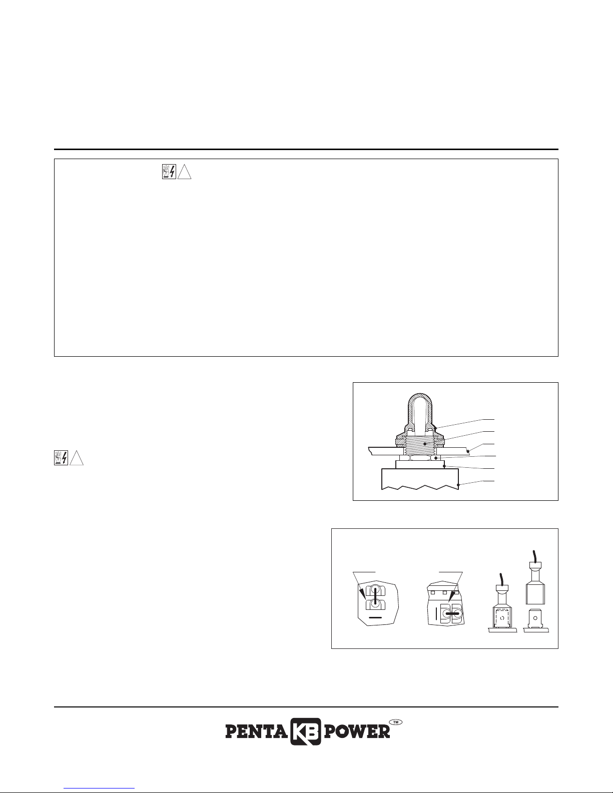
RUBBER BOOT
FRONT COVER
SWITCH BUSHING
HEX NUT
NYLON SPACER
SWITCH BODY
!
REMOVED
TO BE REMOVED
JUMPER
TERMINAL
INSTALLED
TERMINAL
KBAC-27D PC BOARD
REV
STOP
FWD
FWDREV STOP
KBAC-24D PC BOARD
AUTO/MANUAL SWITCH Part No. 9481A
for KBAC Series Inverters with SIAC Signal Isolator (Part No. 9600)
his switch assembly is designed to operate with the following, or higher, Software Revision Codes:
T
KBAC-24D:
he software revision code is printed on the bottom right side of the 2.5” x 7/8” silver ratings label, which is located on the
T
top of the drive. The revision code is given in the format “XX/1.24”.
This product should be installed and serviced by a qualified technician, electrician, or electrical maintenance person familiar with its
operation and the hazards involved. Proper installation, which includes electrical connections, mounting in proper enclosure, fusing
or other overcurrent protection, and grounding can reduce the chance of electrical shocks, fires, or explosion in this product or
products used with this product, such as electric motors, switches, coils, solenoids, and/or relays. Eye protection must be worn and
insulated adjustment tools must be used when working with control under power. This product is constructed of materials (plastics,
etals, carbon, silicon, etc.) which may be a potential hazard. Proper shielding, grounding and filtering of this product can reduce
m
the emission of radio frequency interference (RFI) which may adversely affect sensitive electronic equipment. If further information is
required on this product, contact the Sales Department.
This control contains electronic Start/Stop circuits that can be used to start and stop the control. However, these circuits are never
to be used as safety disconnects since they are not fail-safe. Use only the AC line for this purpose.
Be sure to follow all instructions carefully. Fire and/or electrocution can result due to improper use of this product.
It is the responsibility of the equipment manufacturer and individual installer to supply this Safety Warning to the ultimate end user of
this product.
1.24, KBAC-27D: 1.21, KBAC-29: 1.03, KBAC-45: 1.11, KBAC-48: 1.34.
SAFETY WARNING! Please read carefully before proceeding.
DESCRIPTION
The Auto/Manual Switch assembly is designed for installation on the front cover of
the KBAC inverters. It is used to select either the Main Speed Potentiometer for
“manual operation” or a remote voltage following analog signal for “automatic
operation”, from the SIAC Signal Isolator option (Part No. 9600).
MOUNTING
WARNING! Make sure that the AC line is disconnected before installing
the Auto/Manual Switch assembly.
1. Remove the rubber hole plug assembly that covers the Auto/Manual position by
ewing the r
unscr
2. Align the switch in the front cover hole and mount the Auto/Manual
Switch assembly using the rubber boot that is provided. Do not over
tighten the rubber boot hex nut. See Figur
Note: The switch bushing should protrude approximately 0.15” (3.8mm)
through the front cover
3. Install the SIAC onto the PC board in accordance with the SIAC
Installation and Operating Instructions Manual.
etainer nut that is located on the inside of the front cover.
.
ELECTRICAL CONNECTIONS
1. Remove the jumper assembly that is installed on the FWD and STOP
terminals of the PC boar
back and forth horizontally while pulling them upward. See Figure 2.
2. Install the gray wire from the center terminal of the Auto/Manual Switch
assembly to Terminal “COM” on the KBAC PC board. See Figure 3, on reverse side.
3. Install the green wire from the bottom terminal of the Auto/Manual Switch assembly to Terminal “FWD” on the KBAC PC board. See Figure 3,
everse side.
on r
d. Using pliers, gently r
FIGURE 1 – MOUNTING THE AUTO/MANUAL SWITCH
FIGURE 2 – JUMPER ASSEMBLY
e 1.
ock the female terminals
A COMPLETE LINE OF MOTOR DRIVES
Page 2

INSTALLATION INSTRUCTIONS
Sectional Viewof KBAC
CURJ1VOLT
C
J2
J5
TB2
SIAC
COM FWD
CON1
NC
OFFSET MAX
J11
1
J10
2 VT
J9
CT NO RG
REV
50Hz
CON1
COM1SIG1
R
J8
F
J7
INJ
A60Hz 2X 1X
FWD-5V OV
FIX
J6
ADJ
E
D
CON3 CON2
DBMNDBM
MINJOG MAX
PWR
CLBOOSTDECELACCEL
M
+5V
TB1
A
B
COMPJOG
Auto/Manual Switch
Part No.9481A
To Start/Stop Switch
To LED Board
To Main Speed
Potentiometer
(Layout of Model KBAC-24D
varies slightly.)
Gray (COM)
(Back View)
Green (FWD)
(Part No. 9600)
SIAC Signal Isolator
AUTO/MANUAL SWITCH Part No. 9481A
for KBAC Series Inverters with SIAC Signal Isolator (Part No. 9600)
This switch assembly is designed to operate with the following, or higher, Software Revision Codes:
BAC-24D:
K
The software revision code is printed on the bottom right side of the 2.5” x 7/8” silver ratings label, which is located on the
top of the drive. The revision code is given in the format “XX/1.24”.
FIGURE 3 – KBAC WITH SIAC SIGNAL ISOLATOR & AUTO/MANUAL SWITCH CONNECTION DIAGRAM
.24, KBAC-27D:1.21, KBAC-29:1.03, KBAC-45:1.11, KBAC-48:1.34.
1
KB ELECTRONICS, INC.
12095 NW 39th Str
Outside Florida Call
.kbelectr
www
eet, Coral Springs, FL 33065-2516 • (954) 346-4900 • Fax (954) 346-3377
ee
oll Fr
T
onics.com
(800) 221-6570 • E-mail – info@kbelectr
onics.com
(A40123) – Rev. C – 1/2007
 Loading...