

Page 1

MACWINERY
DIVISION
6465
I8
NilLF
ROAD
STERLING
HEIGHTS,
Mi
4831
4
PnouE:
(586)
731
-3600
i
-800-860-1
?40
k!p&af$mpf??&!
FAX:
$5-
st i 0..
a
yt~
(586)
731
-7464
*
1-800-862-
1710
MODEL WS-I
8
BANDSAW
THANK YOU FOR PURCHASING WlTH KBC MACHINERY. ALL KBC
MACHINES ARE BACKED BY OUR
I
YEAR PARTS REPLACEMENT
WARRANTY. WHEN USED AS INTENDED, AND WlTH PROPER
MAINTENANCE
THIS MACHINE WILL PROVIDE YOU WlTH YEARS OF
TROUBLE-FREE SERVICE. IF YOU NEED PARTS SIMPLY
FILL OUT
THE PARTS REQUEST FORM, AND FAX OR E-MAIL YOUR REQUEST.
ALL OTHER QUESTIONS PLEASE CONTACT US
@
:
KBC MACHINERY
6465 18
MILE ROAD
STERLING
HEIGHTS,MI
48314
PH
(800) 860-1 740
FAX
(800) 862-1740
MACHlNERY@KBCTOOLS.COM
W.KBCTOOLSANDMACHlNERY.COM
www.
KBCTOOLS
.
COM
Page 2

PARTS
REQUEST
FORM
YOUR COMPANY NAME:
STATE/PROVINCE
YOUR NAME
PHONE
#
+
EXT
F.
#
MACHINE INFO:
MAKE/MANFACTURER
MODEL NUMBER
YEAR
MADE
PARTS REQUESTED:
PART#
DESCRIPTION
PLEASE INCLUDE
COPY(S) OF THE PARTS DRAWING EROM THE
MANUAL
AND CIRCLE THE PARTS NEEDED
FAX PARTS REQUEST TO (800)
862-1
740
E-MAIL PARTS REQUEST TO:
machinery@kbctools.com
THANKS; KBC MACHINERY
-
MICHIGAN
Page 3

LK
WBS-1603
3
SPEED
YS
1603N
3
SPEED
Page 4

UNPACKING AND CLEANING
Carefully unpl k the
band saw, stand, and all loose
items
from the cartons. Remove the protective caating
from the machined surfaces of the band saw. This
coating may
be
removed w~th a soft cloth moistened
with kerosene (do not use acetone, gasoline
a
lacquer
thinner
fa
thls purpose). After cleaning, cover all
unpainted surfaces with a
good quality paste
wax.
ASSEMBLING STAND, MOTOR PLA'CE, MOTOR AND MOTOR PULLEY
If you purchased ywr band saw with separate stand and
2.
Return the stand to the upright position and assemble
electricalr NOT factory
mwnted and wired, the stand
is
band saw to stand using four head screws, flat washers,
lock-
supplied as shown in Fig. A. then proceed as follows to washers and nuts. as shown in Fig. 6.
assemble the motor plate, motor and motor pulley.
1.
Turn the stand upside down.
Fig.
A
Page 5

3.
Using the four bolts, flat washers
Consult your Dealer or Catalog for the
for use with vour saw.
and hex head nuts
recommended motor
4.
Assemble motor pulley
11)
Fig. D to the motor shaft.
Make sure the set screw in the motor pulley engages with key
in motor shaft. Using
a
straight edge, make sure the motor
pulley
(11
and driven pulley
12)
are in alignment. If necessary,
both pulleys can
be
moved in or out.
The motor can also be
moved if necessary.
5.
Assemble the V-Belt
(3)
Flg.
E.
to the two pulleys and
adjust for proper belt tension by forwarding or backwarding
the motor. Keep pulleys in alignment when doing this.
Correct belt tension
is
obtained when there
is
approximately
1"
deflection in the center span of the pulleys with lighr finger
pressure.
ASSEMBLING BELT AND PULLEY GUARD
Place the belt and pulley guard
(1)
~ig.
E,
on the surface of
base "shelf".
Use the three hex. head screws to fasten in
Place.
Page 6
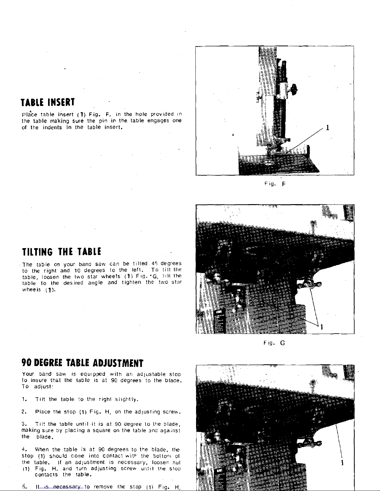
TABLE INSERT
pl;ce table insert (1) Fog.
F,
in the hole povded In
the table making sure the pln
IP
the table engages one
of the
Indents In the table insert.
TILTING THE TABLE
The table o~ your band saw can be tilted
45
degrees
to the rlght and
10
degrees to the left. To tilt the
table,
losen the two star wheels
(1)
I.
lilt thP
table to the desired angle and tighten the two star
wheels
(1).
Fig.
G
90
DEGREE TABLE ADJUSTMENT
Your band saw is equipwd with art adjustable stop
to insure thal the table is at
90
degrees to the blade.
To
adjust:
1. Tilt the table lo the right sl~ghtly.
2.
Place the stop
(I)
Fig.
H,
on the adlusting screw.
3.
Til: the table untilit is at
90
degree to (he blade,
making sure by placing a square on the
table ana against
the blade.
4.
When the table is at
90
degrees to the blade, the
Stop (1) should cone into contact
witk the bottom of
the table.
if an adjustment is necessary, loosen nut
(1) Fig.
H,
and turn adjusting screw unttl the slop
contacts the table.
R.
It is necessary to remove the stop
(1)
Fig.
H,
.
.
Page 7

ADJUS'CING BLADE 'CENSION
On the back of the upper wheel there is a slide bracket
to get the proper tension for
varlous widths ot blades.
W~lh the blade on the wheels, turn the star wheel
(1)
~i.
(I1 to raise or lower the wheel until you provide the
r~ght lenslon lo your blade Over straining is a common
cause of blade breakage and
other unsatisfactory blade
performance
Reiax the
tenslon when the machine is not in use.
TRACKING THE BLADE
After tension has been applied to the blade, revolve the wheels
slowly forward by hand and watch the blade
(1)
Fig.
(J)
to see
that
it
travels in the center of the upper tire.
If the blade
begins to creep toward the front edge, turn the black knob to
the left and this will
tilt
the top of the wheel toward the back
of the machine and will draw the blade toward the center of
the tire.
If the blade creeps toward the back edge, turn the
black knob to the right. Adjust the black knob
(2)
only
a
fraction of a turn at a tine. Never track the blade while-the
machine
is
running.
ADJUSTING LIPPER BLADE GUIDE ASSEMBLY
The upwr blade gufde asspmbly
(1)
Flg.
K,
should
alviays be set as close as possfble to the top surface
of the
mater~al befng cut by loosen~ng lock handle
12)
and moving the gu~de assembly
(1)
to the deslred
posIt1on.
Fig.
I
Page 8

The upper blade guide assembly should also be adjusted
so that the blade
guides
(1)
Fig.
L.
are flat ,wlh the
blade.
ADJUSTING UPPER BLADE GUIDES
I
&
AND BLADE SUPPORT BEARING
The.upper blade guides and blade support bearlngs are
adjusted only after the blade
IS
tensioned and tracklnq
properly.
To adjust proceed as
tollows:
1.
The upper blade guides (1,) Fig.
M,
are held in
place by
reans of the set screws
(2).
Loosen the set
screws
(2)
to move the guides
11)
as close as possible
to the side of the blade,
be~ng carelul not to p~nch
the blade. Then llghten the screws
(2).
2.
The upper blade support bearing
(31
Fig.
51.
.
pre~ents the blade lrom king pushed too lar lo the
back which could damage the
sel in the saw teeth.
The support
bearnng (3) should be set 11!64") SehlM
the blade by loosening knob screw (3) lo move :he
support
bearing
(3)
in or out.
3.
The blaae suppwt bearlng
(3)
sllould also be
adjusted so the back edge of the blade overlaps the
outside dlameter 01 the ball bearing by about 1
!1E".
The bearing
(3)
is
se! on an eccentric and to change
position
remove knob screw (4) and bearlng (3) Fig.
M.
Loosen knob screw (4). and reposition shaft that
F
19.
M
bearing
(3)
is
attached to.
ADJUSTING LOWER BLADE GUIDES
AND BLADE SUPPORT BEARING
The lovier blade
guides
ano blade support nc,lrlng
should be adl~sted at ?he sanie
t,nie as :le .lpper goldes
and bear~ng as fallows.
1. Loosen the two screws
(1)
Fig.
N
,
and nove
Ihe gu~des
(2)
as close as possble to tl,e sde of the
blade,
belng careful not to p~nch the blade.
the^
tlghlen screws (1).
2.
The lower blade support bearing
(3)
Fig.
N.
should be
adjusted so it
isabwt (1164") behind the back of the blade by
Nrning the knob
(4).
Page 9

CHANGING BLADES
To change blades, proceed as follows:
1. Remove the upper and
Laver wheel guards.
2.
Release tension on
the
band saw blade.
3.
Remove the table adjustment pln and table insert.
4. Slip the blade off the wheel and
guide it out through
the slot in the table.
5.
TO install a new blade, reverse the above
pro-
cedure.
BAND SAW BLADES
A band saw blade is a delicate piece of steel that is Any one of a number of conditions may cause a band
subjected to tremendous strain. You can
obtainlong saw blade to break. Blade breakage is, in some cases,
use from a band saw blade if you give it fair treatment. unavoidable,
belng the natural result ot the peculiar
Be sure you use blades of the proper thickness. width stresses to which such blades are subjected. It is,
and temper for the various types
of material lo be cut. however, often due to avoidable causes, most often to
lack of care or
iudgment on the-part of the operator in
Always use the widest blade possible. Use the narrow
blades only for sawing small, abrupt curves and for
fine delicate work. This
wlll save blades ?nd will
produce better work. Band saw blades may be pur-
chased, welded, set
and sharpen-ed ready for use.
For
cutttng wood and similiar materials.'we can supply
them in wtdths
of l/B. 3/16. 114, 3J8, 112 and 314
. .
mounting or adj;sti;lg the blade or guides.
he
most
common causes cfblade breakage are: (1) faulty align-
ments and adjustments of the guides. (2) forcing or
twisting a wide blade around a curve of short radius,
(3) feeding too fast, (4) dullness of the teeth or absence
of sufficient set.
(5)
excessive tightening of the blade,
(6)
top guide set too high above the work being cut,
171
usina a blade witha lumpv or improperly finished
~ncnes.
braze o; weld and,
(8)
cont in;ous runnlng
oi
the saw
blade when not in use for cutting.
I-
File and set the wood cuttino blades whenever vou
find it requires pressure to
mace them cut.
I!
a blaoe
is broken it can be brazed or welded; however, if it
New blades for the standard
18 inch Band Saw are 120 inches
has become badly work-harderled it
Soon
break Ion5 The adjustment will accommodate blader up toa maxi
in another
place. If yo" are not eaul~oed to file. sei
mum length of 121 inches and to a minimum length
OF
,
.7
and braze
weld blades take them to a saw
file; for
119.1/2" inches,
reconditioning. Under average
condit~ons, blades
should
be
resharpened after 4 hours of operation.
OPERATING THE BAND SAW
Before starting the machine, see that all adjustments
are properly made and the guards are in place. Turn
the pulley by hand to make sure that everything is
correc: BEFORE turning on the power.
Keep the top guiae down close to the wak at all times.
Do not force the material against the blade too hard.
Light contact with the blade will
ermit easier following
of the' line and prevent
undue friction. heating and
work-hardening of the blade at its back edge.
KEEP THE SAW
BLADE
SHARP and you will find
that very little forward pressure is required for average
cutting. Mcve
th stock against the blade steadily
and no faster than will give an easy cutting movement.
Avoid
twist~ng the blade by trylng to turn snarp corners.
Remember you must saw around corners.
CUT'TING CURVES
When cutting curves, turn the stcck carefully so that
the blade may follow without being twisted. If
a
curve
is so abrupt that it is necessary to repeatedly back up
and
cut a new keri, either a narrow blade is needed
or a blaae with more set is required. The more set a
blade has, the easier it will allow the
stock to be
turned,
but the cut is usually rougher than where a
medium amount of set is used.
In withdrawing the piece being cut, in order to change
the cut, or for any other reason, the operator must be
careful that he
does not accidentally draw the blade
off the wheels. In most cases it is easier and safer to
turn the stcck and saw out through the waste material,
rathe: than try to withdraw the stcck from the blade.
Page 10
Page 11

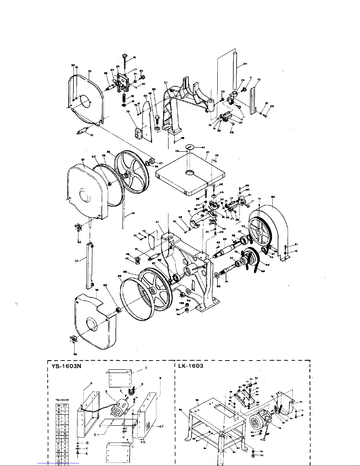
PARTS LIST
Description
I
5
1
Support Bracket For Upper Guide
I
11
6 i Screw
I
14
7 Guide Block 2
8 Square Guide Block 4
9 Cross Screw 8
I
10 1 Flat Washer
I
20
I I
rKnob Screw
1
14
12 Guard Plate
I
13 Spacking Sleeve
2
pp
14 Ball Bearing 620022 2
15 C-Clip 2
16 Blade Adjust Screw
I,
17 Upper Wheel Sliding Brkt.
I
18 Sorinr
I
.
-
19 Square Bolt
-
I
20 Knob Screw
I
21 Nut
1
Upper Wheel Shart
Ball Bearing 620222
,
..
29 Wheel Protector
2
30
1
Uooer Wheel Guard (Inner)
I
11
. .
31 Stud 4
32 Upper Wheel Guard
(Outter)
I
33 ScrLw 4
I
I
34 1 Flat Washer
18
35 1 Nut
I
6
36 1 C-Ring 4
37 Flat Washer 6
38 1 Pin 2
39 1 Screw
I
I
40 1 Flat Washcr
1
2
41
1
~ase
1
42 1 Nut
I
43 I Saw Blade
I
,
49 1 Trunnion Clamp Shoe
2
50 ( Trunnion
?
MEASUREMENTS:
52'x 23.2*x15*
CUFT
10.5
N.W.
Washer
 Loading...