

Quick Start Guide
Qty
Description
1
WESII-AA-CA APHost RF module with integrated
directional antenna
1
WESII-AC-CA Client RF module with integrated
2
24VDC power supplies w/ integrated POE injector
2
Wall / pole-mount bracket and assembly kit (each
includes):
1 - Pole clamp bracket
1 - Bracket body (L/R swivel piece)
2 - Connecting pieces (up/down alignment clamps)
2 - ¼” hex nuts
1 - 27mm, 1.06” long ¼” hex bolt
2 - Flat washers 15mm, 0.59”
2 - Locking washers 10mm, 0.39” long
1 - U bolt
2 - ¼” lock washers
Parameter
Setting
LAN IP Address
192.168.1.200 (AP-Host)
192.168.1.201 (Client)
GUI User ID
admin
GUI Password
password
SSID
KBC-WESII
Pre-shared Key
11111111
Frequency selection
(Host only)
Auto
Bandwidth
20/40 MHz
MAC-Filter
00:00:00:00:00:00
WESII-KT
Host/Client Pt-to-Pt Wireless Ethernet Kit
Introduction
This document provides instruction for basic set
up and installation of the WESII-KT. More
detailed information can be found on the KBC
Networks website (see Downloads section).
Features of this QSG
Contents of the WESII-KT box
Necessary equipment to proceed
Web browser configuration steps
o KBC default settings are usually
sufficient for operation
Default configurations restoration
process and details
LED indication
Support contact, FCC & Warranty Info
System Contents
Downloads
Installation manual – includes other features &
functions:
http://www.kbcnetworks.com/downloads
(Click on Manuals&QSG, then Wireless, then Manuals
again)
Specification Sheets:
http://www.kbcnetworks.com/downloads
Equipment Required for Physical
Deployment
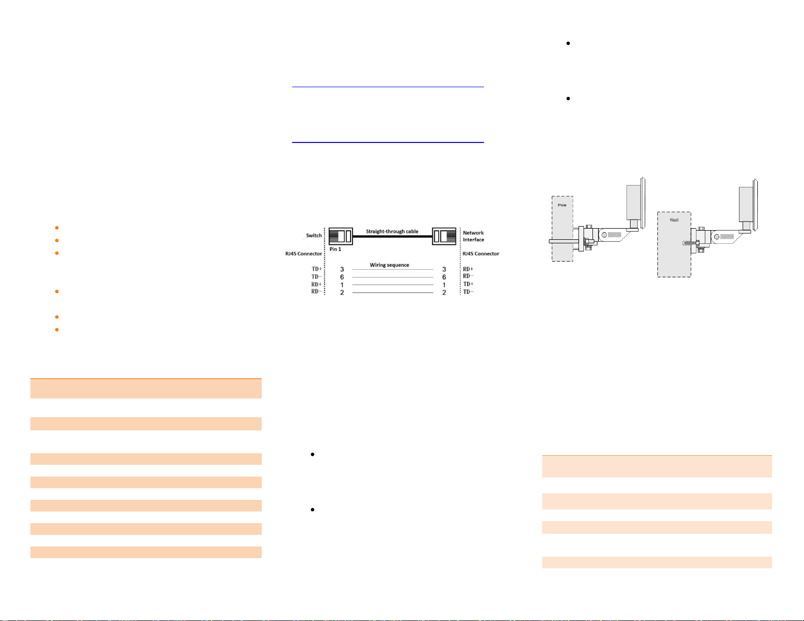
Two straight through Ethernet cables are
required for connection from the WESII APHost
or Client to the supplied PSU/PIM unit.
Note: The power supply / injector device
supplied must be used with the WESII series.
KBC recommends shielded outdoor rated
Ethernet cables when connecting near power
outlets & when exposed to the elements.
Physical Deployment
This equipment must be installed and operated
in accordance with instructions found in the KBC
Networks’ manual. Damage due to misuse is not
covered by warranty. Here are some important
bullet points:
You will need to first feed the Ethernet
cable through the black strain relief (ie
weather coupler protection piece) prior
to crimping on the RJ45 connector.
Hand-tighten the Ethernet cable
connection protecting piece, do not
tighten further. Damage due to overtightening the black weather coupler into
its RJ45 housing is not covered under
warranty.
Do not mount the antennas horizontally
or upside down. The black external LAN
port is to be pointing downward with no
ability for water to get into the housing.
Once the cable is inserted into the
external LAN port RJ45, a small flat head
screwdriver, or similar tool, is needed to
release the tab of the RJ45 connector on
your cable. If you pull the cable without
releasing the tab, it will cause damage
to the port.
Default Configurations
The WESII-KT has been pre-set as a pair. The
WESII-AA-CA APHost is locked to its Client and
vice-versa. Refer to the serial number label on
each device which will indicate the serial number
of its mate radio. These two units have also
been physically strapped together because they
were factory set for another. A restore to
defaults to one or both devices will erase their
factory paired configuration resulting in the need
to field/bench re-configure. A restore to factory
defaults will return the units to the following:
Custom Configuring the WESII-KT
password
5
L
P
192.168.1.x Static IP
Ethernet
Straight-through
PSU-Injector
WESII RF Module
P= POE
L= LAN
Signal strength
indication
Connected Client
APHost SSID
3
1
2
4 6 6.1
6.2
6.3
6.4
7.1
7.2
7.3
7.4
Your kit is already pre-set for most deployments.
The following is provided if you desire to change
settings via the WESII web browser interface.
To access the web browser interface:
1. Connect Ethernet cables as shown above.
2. Plug in the PSU-Injector into an outlet.
The status LED 1 will flash then LEDs 5 &
6 will be solid green.
3. Ensure that your computer is set to the
same 192.168.1.x subnet as the WESII.
4. To access the WESII-AA-CA APHost:
To access the WESII-AC-CA Client:
If the APHost and Client are each powered and
still under default settings they will connect:
If the connection is weak or if there are multiple
WESII links in the same environment, changing
the APHost frequency is recommended.
Changing the frequency:
6. Click on “KBC-WESII” as a short cut to get
to the Wireless Configuration. The menu
will provide ability to make configuration
changes.
6.1 KBC recommends 20 MHz and a static
frequency channel for most
deployments.
6.2 Click on “Wireless” next to “Interfaces”
then click on “Spectrum” from the
Wireless Overview to determine
appropriate frequency to use.
Re-configuring the IP Addresses:
If you have multiple WESII kits or should
network requirements restrict the unit IP
address or if you desire your own set of IPs for
the WESII units, see the instructions below.
7. If the IPs need to be changed:
7.1 Click on Network
7.2 Click Interfaces, “LAN” will appear under
“Interfaces”
7.3 Click “LAN” and the window shown below
will open:
5. Enter “password” to access the Status
page.
Status shows link connection and other
setting specifics.
7.4 Change the IPv4 address to your needed
IP, click “Save&Apply”
6.3 Return to the Wireless Configuration
page to select your desired frequency.
6.4 Click “Save & Apply”
In the above example, the Host IP was changed from
the default 192.168.1.200 to a different IP address.

Configuring the Client unit:
1
2
1
2
3
4
10
11a
11b
8. If you have made any changes to the AP-
Host SSID, encryption or pre-shared key
then you will need to re-join the Client to
the new APHost “network”.
9. Follow steps 1-5 above this time using
192.168.1.201 for the default Client IP.
10. Click on “Network” then “Wireless” and
click “Scan”
11. Select your Host from the list of Access
Points. And enter the unit pre-shared key
to connect to it.
Note: Allow up to 2 minutes for the units to
connect to each other.
Note: Record all changes and details. MAC
addresses, custom IP addresses, SSIDs and/or
pre-shared keys and such detail needed for the
units to link which are not kept on file will
require a hard reset. Resets performed in the
factory are subject to a non-warranty repair
charge.
Reset to Default Settings
Via Interface:
1) Click on “System” then “Firmware”
2) Click on "Perform Reset”
Via External Reset Button:
The WESII can also be hard reset from the
button on the underside of the case.
1) Power up the WESII APHost or Client RF
module and allow it to go through its
reboot process.
2) Remove the phillips head screw (be sure
to replace it when complete).
3) Insert a small screwdriver in order to push
the reset button.
4) Hold the button for approximately 10
seconds and release.
5) Ensure that your computer is set to the
192.168.1.x subnet and the unit will be
accessible on the configurations shown in
the section below.
Note: The LEDs will not light up or flash during
the reset process.
Note: A restore to defaults will erase custom
configuration settings and disable the MAC
lock feature.
Re-Locking the Host to its Client MAC:
From the Status page, click on the blue SSID
which will take you to the configuration page.
1) Click on “MAC-Filter”
2) Select “Allow Listed Only”
3) Enter the Client’s Radio 1 MAC address.
4) Click “Save & Apply”
5) Perform steps 1-4 on the Client side,
entering the APHost Radio 1 MAC there.
WESII Status Indicators (Left to Right)
1. Status/Signal Strength Indicator
In power up / boot up process
40+ RSSI
RSSI less than 40 (or no link if the
other RSSI LEDs are not on)
2. Signal Strength Indicator
Solid green 30-39 RSSI
RSSI less than 30 (or no link if the
other RSSI LEDs are not on)
3. Signal Strength Indicator
20-29 RSSI
RSSI less than 20 (or no link if the
other RSSI LEDs are not on)
4. Signal Strength Indicator
10-19 RSSI
RSSI less than 10 (or no link if the
other RSSI LEDs are not on)
5. Network – Ethernet link activity
Link activity established
Link activity from WESII to
connected Ethernet device or across
wireless link.
No link to Ethernet cable connected
device. (not indicative of wireless
link/strength)
6. Power
Power applied.
No power to unit. Ensure that the
power injector and power supply is being
used. These units will not power directly
from a POE switch.
Flashing LED
Solid LED
LED off
Note: The LEDs do not change colors.

Compliance
FCC
Industry Canada
RF Exposure Warning
CE Marking
RoHS/WEEE Compliance Statement
Installer Compliance Responsibility
Devices must be professionally installed and it is
the professional installer's responsibility to make
sure the device is operated within local country
regulatory requirements.
Please visit our website at
www.kbcnetworks.com for full
compliance statements and
information
Need Help?
Visit our website http://www.kbcnetworks.com
or contact your nearest KBC office or dealer:
USA
Phone: +1 949 297 4930
Toll Free: +1 888 366 4276
Monday – Friday
7am-5pm Pacific Time
Email: techsupport@kbcnetworks.com
EMEA
Phone: +44(0)1622 618787
Email: emeatechsupport@kbcnetworks.com
APAC
Phone: +65 98463323
Email: apactechsupport@kbcnetworks.com
FCC Required Information
Radio Frequency Interference Statement for
Class B Digital Devices
This equipment has been tested and found to comply
with the limits for an intentional radiator, pursuant to
Part 15, subpart C of the FCC Rules. This equipment
generates, uses and can radiate radio frequency
energy. This equipment generates, uses, and can
radiate radio frequency energy. If not installed and
used in accordance with the instructions, it may
cause harmful interference to radio communications.
The limits are designed to provide reasonable
protection against such interference in residential
situations. However, there is no guarantee that
interference will not occur in a particular installation.
If this equipment does cause interference to radio or
television reception, which can be determined by
turning the equipment on and off, the user is
encouraged to try to correct the interference but on
or more of the following measures:
Re-orientate or relocate the receiving antenna
of the affected radio or television.
Increase the separation between the
equipment and the affected receiver.
Connect the equipment and the affected
receiver to power outlets on separate circuits.
Consult the dealer or an experienced radio/TV
technician for assistance.
Shielded cables must be used with this unit to
ensure compliance with Class B FCC limits.
Changes or modifications to this unit not
expressly approved by the party responsible
for compliance could void the user’s authority
to operate the equipment.
Changes or modifications not expressly
approved by KBC could void the user’s
authority to operate the equipment.
FCC Power Output Restrictions
The FCC does not require licensing to implement this
device. License-free operation in the industrial,
scientific and medical band is documented in FCC
Rules Part 15.247. It is the responsibility of the
individuals designing and implementing the radio
system to ensure compliance with any pertinent FCC
Rules and Regulations. This device must be
professionally installed.
Exposure to Radio Frequency Fields
The WESII is designed to operate on the 5 GHz
frequency band with up to 50 Watts EIRP maximum
transmit power. This level of RF energy is above the
Maximum Permissible Exposure (MPE) levels
specified in FCC OET65:97-01. The following
precautions must be taken during installation of this
equipment:
The installed antenna must not be located in a
manner that allows exposure of the general
population to the direct beam path of the
antenna at a distance less than 20cm.
Installation on towers, masts, or rooftops not
accessible to the general population is
recommended or alternatively mount the
antenna in a manner that prevents any
personnel from entering the area within 20cm
from the front of the antenna.
It is recommended that the installer place
radio frequency hazard warnings signs on the
barrier that prevents access to the antenna.
During installation and alignment of the
antenna, do not stand in front of the antenna
assembly.
During installation and alignment of the
antenna, do not handle or touch the front of
the antenna.
Warranty Information
KBC extends the following LIMITED WARRANTY to the original
owner/purchaser of this product as follows:
- Two years from the date of initial sale for all wireless products.
If, within the specified warranty period, this product, or any part or
portion thereof, shall prove upon examination by KBC, to be defective
in material or workmanship, KBC will repair or replace such part or
portion at KBC’s option. The warranty period on the repaired or
replaced part or portion of this product shall be limited to the
unexpired term of the original warranty. The buyer shall be responsible
for all shipping and transportation of the product to KBC for any
performance under this warranty.
Conditions and Exceptions:
a. Any accident to this product, any misuse or abuse, alternation, use
in modified form, or any attempt to repair this product shall void this
warranty. These conditions to the warranty include, but are not limited
to, incorrect power connections, physical damage due to mechanical
shock, exposure to moisture, and circuit modification.
b. SHOULD THIS PRODUCT PROVE DEFECTIVE FOLLOWING
PURCHASE, THE BUYER, NOT THE MANUFACTURER, DISTRIBUTOR, OR
RETAILER, ASSUMES THE ENTIRE COST OF ALL SERVICING OR
REPAIR, EXCEPT AS OTHERWISE PROVIDED BY THE TERMS OF THIS
WARRANTY.
c. FOR BREACH OF ANY WRITTEN OR IMPLIED WARRANTY ON THIS
PRODUCT, THE BUYER IS LIMITED TO THE FOLLOWING DAMAGES. (1)
THE COST OF LABOR TO REPAIR OR REPLACE DEFECTIVE PARTS OR
PORTIONS OF THIS PRODUCT, AND (2) THE COST OF THE REPAIRED
OR REPLACE PARTS OR PORTIONS OF THIS PRODUCT.
d. NO OTHER EXPRESSED OR IMPLIED WARRANTIES HAVE BEEN
MADE OR WILL BE MADE ON BEHALF OF KBC WITH RESPECT TO THE
SALE, REPAIR, INSTALLATION, OPERATION, OR REPLACEMENT OF
THIS PRODUCT. KBC DISCLAIMS ANY IMPLIED WARRANTY OF
MERCHANTABILITY OF THIS PRODUCT OR ITS FITNESS FOR ANY
PURPOSE, AND THE BUYER AGREES THAT THIS PRODUCT IS SOLD
“AS IS” AND THAT THE ENTIRE RISK OF QUALITY AND PERFORMANCE
OF THIS PRODUCT IS WITH THE BUYER, EXCEPT AS OTHERWISE
PROVIDED BY THE TERMS OF THIS WARRANTY.
e. Some states/jurisdictions do not allow exclusions or limitations of
incidental or consequential damages, or limitations on how long an
implied warranty lasts, so the above exclusions or limitations may not
apply to you.
f. If you do not wish to be bound by any of the provisions in this
warranty, please return the product(s) immediately.
4. Contact your dealer regarding return authorizations for out of
warranty repairs and any further product information.
This warranty does not apply in Australia.
 Loading...