

KBC WESII-KT, WESII-AB, WESII-AC, WESII-AA User Manual

WESII
Wireless Ethernet System
User Manual
WESII-KT
WESII-AA-xx Series
WESII-AB-xx Series
WESII-AC-xx Series

WESII User Manual
Manual-WESII-Rev1205A
Copyright © KBC Networks 2012 Page 2 of 48 www.kbcnetworks.com
TABLE OF CONTENTS
1 OVERVIEW .................................................................................. 3
1.1 Introduction ............................................................................................................................................ 3
1.2 Technical Specification ............................................................................................................................ 5
2 INSTALLATION ............................................................................. 7
2.1 Package Contents .................................................................................................................................... 7
2.2 Configurations ........................................................................................................................................ 7
2.3 Physical Connections ............................................................................................................................... 8
2.4 Basic Installation Method ..................................................................................................................... 10
3 GRAPHICAL USER INTERFACE ......................................................... 17
3.1 Accessing the WESII Graphical User Interface (GUI) ............................................................................. 17
3.2 Menu Options ....................................................................................................................................... 18
4 TROUBLESHOOTING .................................................................... 38
4.1 Visual Inspection ................................................................................................................................... 38
4.2 Test Cable Connections ......................................................................................................................... 38
4.3 GUI Tools ............................................................................................................................................... 38
4.4 Contact KBC Technical Assistance ......................................................................................................... 39
5 WARRANTY ............................................................................... 40
5.1 Warranty Information ........................................................................................................................... 40
6 SAFETY, APPROVALS AND REGULATORY DOMAIN INFORMATION ................ 41
6.1 Safety Instruction .................................................................................................................................. 41
6.2 FCC Required Information ..................................................................................................................... 41
6.3 Industry Canada Restrictions ................................................................................................................ 43
6.4 CE Regulatory Statement ...................................................................................................................... 43
6.5 Environmental Restrictions of Wireless Devices .................................................................................... 45
7 INSTRUCTION OF DISASSEMBLY ...................................................... 46
ANNEX A - GENERAL PUBLIC LICENSE STATEMENT ..................................... 47

WESII User Manual
Manual-WESII-Rev1205A
Copyright © KBC Networks 2012 Page 3 of 48 www.kbcnetworks.com
1 Overview
1.1 Introduction
This manual covers the WESII series. KBC Networks’ WESII wireless products are
high performance, IEEE802.11n, IEEE802.11h, 5GHz, up to 100Mbps wireless
transceivers with a range of antennas to suit applications. They are designed for use
in a wide range of operating temperatures in non-environmentally conditioned,
outdoor applications. The primary function of the system is to replace Ethernet
cables where it is not practical or cost-effective or where it is beyond distance
limitations. WESII has been specifically designed to transmit constant streaming
video but can also be used to send and receive standard Ethernet data packets or to
operate as a WiFi Access Point. The units can be configured as a long range point to
point wireless bridge or as a multipoint receiving antenna, communicating to
numerous transmitting Client, or Station, devices. This manual covers all operations
and functions of the point to point (Ptp) and point to multipoint (Ptmp) systems.
1.1.1 WESII Point to Point (Ptp)
The WESII-KT-x and WESII-AA-xx Series (where “xx” denotes the choices for the
unit type, power connector and firmware) are the KBC Networks’ Ptp systems units
available. The Ptp units support transmission of Ethernet data to provide a long
range wireless Ethernet bridge where there is clear line of sight and no interference
on the frequency used. Each Ptp Host/AP can connect to only one Client via a MAC
Address lock. Additional Ptp Host/APs can be deployed using a separate frequency
and MAC Address lock with the second Client MAC Address locked into the second
WESII Host/AP in the environment. As will be explained in the MAC Address lock
process in Section 3.2.5, the Client must be told the Host/AP’s MAC Address and vice
versa in order to communicate. The Host/AP and Client are included in the WESII-KT
and WESII-KT-ED kits. The Ptp Host/AP is included in the WESII-AA Series product
part numbers. Clients from WESII-AC-xx Series product part numbers can be
configured to connect to a Host/AP from any of the other Host/AP part numbers
provided that it is not the second Client attempting to connect to a single point Ptp
Host/AP.
1.1.2 WESII Point to Multipoint (Ptmp)
The WESII-AB-xx Series (where “xx” denotes the choices for the unit type, power
connectorand firmware) are the KBC Networks’ Ptmp systems available. In most
cases, the WESII-AB-xx Ptmp Host will connect to one or more WESII-AC-xx series
Clients. The WESII-AB-xx Host can also be configured as a WiFi Access Point and
connect to a client device other than KBC Networks’ WESII Clients. The Ptmp
systems support transmission of Ethernet data to provide a long range wireless
Ethernet bridge where there is clear line of sight and no interference on the
frequency used. Additional Ptmp Host/APs can be deployed using a separate
frequency and SSID structure for the group and (if desired) preferred MAC Address
lock to AP on each of the associated Clients. These functions ensure that the
appropriate Client groups connect to the correct Host/AP. The Ptmp Host/AP is
included in the WESII-AB-xx Series product part numbers along with the appropriate
accessories.

WESII User Manual
Manual-WESII-Rev1205A
Copyright © KBC Networks 2012 Page 4 of 48 www.kbcnetworks.com
1.1.3 External Antenna Host/Client
The WESII-Ax-Dx Series (where “x” denotes the choices for the unit type, power
connector and firmware) is an example of KBC Networks’ Ptp and Ptmp systems and
product part numbers which are housed in a chassis which provides connectors for
external antenna options. The external antennas can be either omni-directional or
directional MIMO antenna types that are higher gain than are available in the
integrated antenna WESII kits. The external antenna option gives the user the ability
to select the appropriate antenna type and gain for the application. It is the
responsibility of the user to integrate the appropriate gain antenna allowed by local
regulations and/or lower the power output on the radio. KBC Networks accepts no
responsibility for illegal deployments. See end of section 3.2.5 for power output
details.

WESII User Manual
Manual-WESII-Rev1205A
Copyright © KBC Networks 2012 Page 5 of 48 www.kbcnetworks.com
1.2 Technical Specification
WESII Specification
Standards
IEEE Standards
IEEE 802.3 10BASE-T
IEEE 802.3u 100BASE-TX
IEEE 802.3x Full Duplex
IEEE 802.11a 5GHz
IEEE 802.11n MIMO
IEEE 802.11h ETSI DFS & TPC
Radio
Frequency (MHz)
USA & Canada:
5745, 5765, 5785, 5805, 5825
Europe:
5500, 5520, 5540, 5560, 5580, 5600
5620, 5640, 5660, 5680, 5700
Frequency Operation
Auto-select
User static selectable
Dynamic Frequency Selection (ETSI
DFS)
Power Output
23dBm max1
Transmit Power Control (ETSI TPC)
Channel Capacity
Selectable 5, 20 or 40MHz
Modulation
OFDM
Receive Sensitivity
(Tolerance ± 2dbm)
MCS HT 20 HT 40
8 -97dBm -92dBm
9 -94dBm -90dBm
10 -92dBm -87dBm
11 -87dBm -84dBm
12 -84dBm -82dBm
13 -80dBm -78dBm
14 -79dBm -76dBm
15 -77dBm -74dBm
Antennas
5dBi
Omni-directional
9dBi
Directional integrated patch
Dual polarization
Beamwidth:
Azimuth: Horizontal 65°, Vertical 65°
Elevation: Horizontal 33°, Vertical 33°
17dBi
Directional integrated patch
Dual polarization
Beamwidth:
Azimuth: Horizontal 30°, Vertical 33°
Elevation: Horizontal 17°, Vertical 17°
1
Territory specific.

WESII User Manual
Manual-WESII-Rev1205A
Copyright © KBC Networks 2012 Page 6 of 48 www.kbcnetworks.com
System
Data throughput2
(max values – limited by 10/100 port)
HT5 HT20 HT40
17Mbps 99Mbps 99Mbps
Latency
< 10 mS
Power
Power input (supplied by PIM)
24Vdc, 500mA
Reverse voltage protected
Power method
Passive PoE
PoE cable spec
100m on 24AWG Cat5/5e/6/6e
Mechanical
Casing
IP66
Dimensions (Patch L x W x D)
245mm x 245mm x 76mm
9.625” x 9.625” x 3”
Weight
420g
15oz
Installation
Wall-mount or pole-mount
Environmental
Operating Temperature
-40° ~ +74°C / -40° ~ +165°F
Storage Temperature
-40° ~ +90°C / -40° ~ +194°F
Operating Humidity
5% to 95% non-condensing
Connectors
10/100 Electrical
1 x RJ45
Power
Passive PoE
Approvals
FCC Part 15 subpart C
Class B
IC ID# 7849A-N523ESD
CE
Class B
EN 55024 (IEC61000-4-2,3,4,5,6,8,11)
Electromagnetic Immunity
EN 55022 (CISPR 22)
Electromagnetic Interference
(Conduction and Radiation)
EN 60 950: 1992+A1; 1993+A2;
1995+A4; 1996+A1; 1997
Low Voltage Directive
EN 300 328-2
EN 300 826
EN 301 489-17
EN 301 893
R&TT Directive (1999/5/EC)
2
Assumes an ideal environment with maximum signal rates & within receive
sensitivity specification.

WESII User Manual
Manual-WESII-Rev1205A
Copyright © KBC Networks 2012 Page 7 of 48 www.kbcnetworks.com
2 Installation
2.1 Package Contents
WESII RF Module (Host/AP or Client; WESII-KT comes with one Ptp Host and
one Client)
One mid-span compliant Power Injector Module for each WESII unit included
One 24Vdc, 500mA PSU for each power injector module included
Wall or pole mount bracket and assembly kit for each RF module included
Quick Start Guide
Consult the Quick Start Guide for the exact list of components for the particular part
number ordered. Please contact you dealer or distributor if a part is missing or
damaged within 10 days of receiving the products.
2.2 Configurations
Products are available in either integrated antenna or external antenna chassis, with
the following configurations:
Part number
Topology type
Unit type
Antenna type
WESII-AA-A*
Ptp
Host
5dBi
WESII-AA-B*
Ptp
Host
9dBi
WESII-AA-C*
Ptp
Host
17dBi
WESII-AA-D*
Ptp
Host
Selectable
WESII-AB-A*
Ptmp
Host
5dBi
WESII-AB-B*
Ptmp
Host
9dBi
WESII-AB-C*
Ptmp
Host
17dBi
WESII-AB-D*
Ptmp
Host
Selectable
WESII-AC-A*
Ptp/Ptmp
Client
5dBi
WESII-AC-B*
Ptp/Ptmp
Client
9dBi
WESII-AC-C*
Ptp/Ptmp
Client
17dBi
WESII-AC-D*
Ptp/Ptmp
Client
Selectable
WESII-KT-*
Ptp
Host & Client
17dBi
Where * denotes the power supply and firmware.
WESII User Manual
Manual-WESII-Rev1205A
Copyright © KBC Networks 2012 Page 8 of 48 www.kbcnetworks.com
2.3 Physical Connections
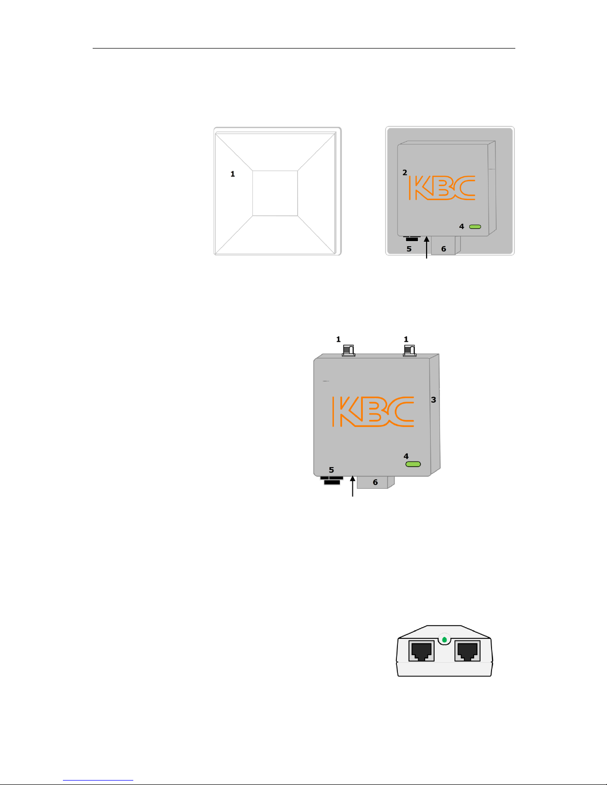
2.3.1 Integrated Patch Antenna Chassis
2.3.2 External Antenna Chassis
Rear view
2.3.3 Power Injector Module (PIM)
Note: The Power Injector Modules are not weatherproof units and must be protected
from moisture.
There are 2 different PIM modules currently available with WESII products,
connection details are below:
Front view
Rear view
1. Patch antenna cover
2. Serial number label
3. Internal RF module
enclosure
4. Status LEDs
(See section 2.3.4 for
description)
5. LAN port (RJ45)
6. Mounting block
7. Reset to default button
1. Antenna ports, attach screw down omni-
directional antennas (for directional
antennas, connect jumper LMR-200 cable)
2. Serial number label
3. Internal RF module enclosure
4. Status LEDs
(See section 2.3.4 for description)
5. LAN port (RJ-45)
6. Mounting block
7. Reset to default button
3
2
7
1. DATA IN – Connect to Ethernet device
2. POWER LED – Indicates power is on when lit
3. P+DATA OUT – Connect to the WESII unit
4. Power supply input (at rear of PIM)
Front view
4
1 2 3
7
WESII User Manual
Manual-WESII-Rev1205A
Copyright © KBC Networks 2012 Page 9 of 48 www.kbcnetworks.com
POE +
Power
OUT
IN
Local Power
Remote Power
PIM Top View
PIM Side View (Power and Output)
PIM Side View (Input)
Note: KBC Networks’ WESII units are mid-span compliant and must be powered
using the supplied power injection module.
2.3.4 RF Module LED Description
1. Status/Signal Strength Indicator – 40 RSSI
2. Signal Strength Indicator – 30 RSSI
3. Signal Strength Indicator – 20 RSSI
4. Signal Strength Indicator – 10 RSSI
5. Ethernet Link Activity
6. Power
LED Boot Up Process 2.3.4.1
Upon connection of an Ethernet cable from the PIM to the unit, the Power LED
6 will light.
After 1 second RSSI LEDs 1, 2 & 3 illuminate.
RSSI LEDs 1, 2 & 3 then go off.
After 5 seconds the Ethernet Link Activity LED 5, illuminates.
At the same time the Signal Strength Indicator, LED 1 flashes for
approximately 2 seconds.
LEDs 1 & 5 then switch off.
LED 5 comes on again and flashes intermittently showing that a connection is
established.
After approximately 1 – 2 minutes RSSI LEDs 1, 2, 3 & 4 will light depending
on the level of signal strength.
Note: WESII units with EMEA firmware set to frequencies between 5600 – 5650MHz
and any channels that overlap these frequencies may take up to 13 minutes to
connect due to the Channel Availability Check (CAC) time requirement of ETSI
Dynamic Frequency Selection (DFS). See section 6.4 for further details.
1 2 3 4 5
6
1 23
1.Power – Power supply input
2.OUT – Connect to the WESII unit
3. IN – Connect to the Ethernet device
WESII User Manual
Manual-WESII-Rev1205A
Copyright © KBC Networks 2012 Page 10 of 48 www.kbcnetworks.com
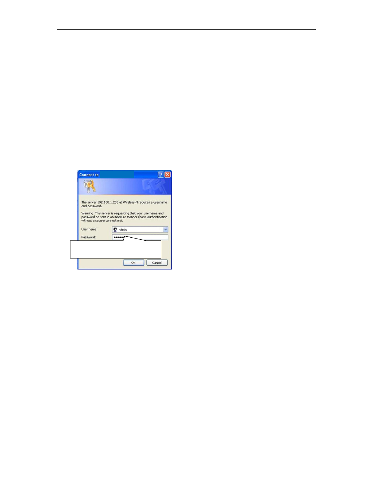
Default User Name: admin
Default Password: admin
2.4 Basic Installation Method
2.4.1 Bench Test Set Up
KBC Networks recommends that all equipment be bench tested before being
installed on site. Four straight through Ethernet cables are required.
Note: It is recommended that for bench testing units be placed face downwards
with a distance of 5 – 10m between them to avoid saturation.
1. Remove the WESII Host/AP, Client, Power Supplies Units (PSUs) and Power
Injector Modules (PIMs) from their boxes. Connect a straight through cable from
“Data In” on one of the PIMs to a laptop or PC LAN port. Connect another
Ethernet cable from “P+Data Out” on the same PIM to the WESII Host LAN port.
2. Verify that the static IP address on the laptop is set to the 192.168.1.x subnet
(refer to provided documentation for exact IP per serial number) and open a
web browser to access the Host/AP on its 192.168.1.200 default IP address or
Client on its 192.168.1.201 default IP address.
3. Enter the default user ID and password (admin / admin) to access the GUI.
Disable any other Network Interface connection including the laptop/PC WiFi
access that is not being used to access the WESII RF Host/AP or Client.
4. Select the Basic Wireless menu and choose the country for the appropriate
regulatory domain. Click “Apply Settings” and then “Save” next to “Save
Configuration Changes”.
Note: It is the sole responsibility of the installer of the KBC Networks’ WESII
equipment to ensure that the correct Country Code is selected to comply with the RF
regulatory requirements of the country in which the equipment is installed. KBC
Networks accepts no liability for incorrect selection.
5. To set the Host/AP to a specific channel manually, select one of the available
frequencies and apply/save changes. When selecting a channel on site, first click
“Interference Analyzer” to determine available frequencies in the environment.
For WESII units with EMEA firmware it is recommended that 5500MHz is
selected manually for initial set-up, see section 6.4 for further details.
6. Follow steps 3 & 4 above to configure the Client. The Client will not need the
frequency indication but will need to match the Country Code, SSID code,
Channel Spectrum Width and have its MAC addressed locked to the Host in
order for the two units to talk wirelessly
WESII User Manual
Manual-WESII-Rev1205A
Copyright © KBC Networks 2012 Page 11 of 48 www.kbcnetworks.com
7. If there are multiple Host/APs and associated Clients, configure the additional
hosts as in steps 3 – 5 while noting their MAC Addresses. (including the first
host) & SSID. Each Client intended to talk with a particular Host must be
configured to connect with its host via SSID filtering under the Client’s “Remote
Preferred AP MAC” section but will not require their MAC addresses to be locked.
Additional Host MAC addresses can be inserted as fail over hosts. Refer to the
provided documentation regarding any preset configurations to match up the
correct Client(s) to the correct Host/AP to which it/they will connect.
8. Unless more advanced set up is desired, the antennas are configured for
installation at this point. For advanced configuration see section 3.2.6.
2.4.2 Replacing / Adding a WESII Module from/to the Existing
Application
The WESII Host/AP connects to its Client(s) based on MAC Address. A Ptp Host/AP
can connect to one Client MAC Address only, whereas the Ptmp Host/AP can connect
to multiple Clients. If a Host/AP is being replaced, the Clients with which it is
required to communicate must be configured within the Host/AP System page. If a
Client is being replaced, or added to a Ptmp network, its SSID must be configured to
match the Host/AP SSID configuration (if changed from default configurations). In
addition (if replacing / adding a Host/AP from/to the existing application), the
Host/AP must be configured to an available frequency.
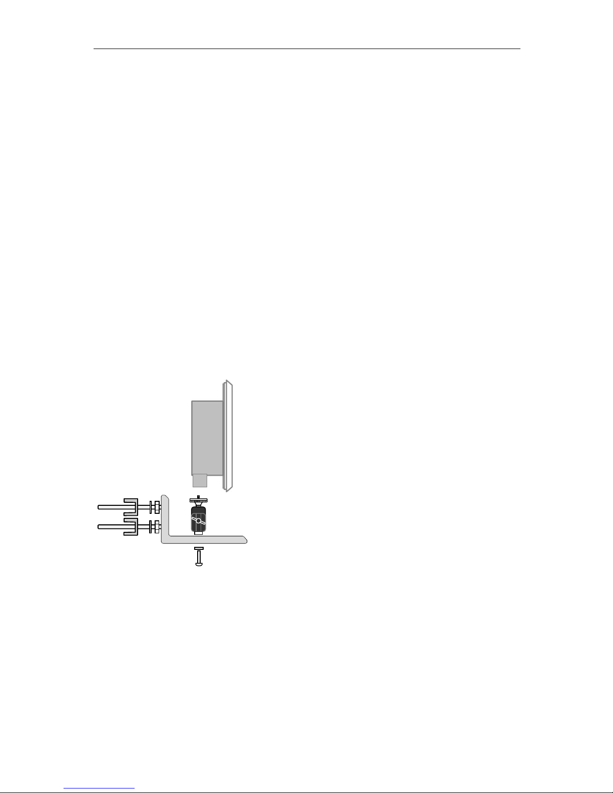
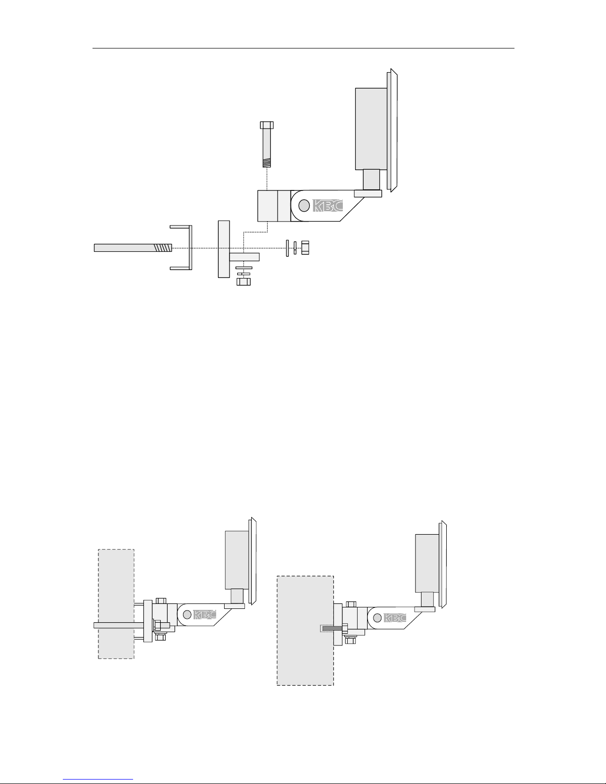
2.4.3 Pole and Wall-mount for Directional WESII Antennas
There are 2 different mounting brackets currently available with WESII products,
details are below:
Remove all packaging material
Connect the black mounting assembly (which has the adjustment swivel) to the
mounting L-shaped bracket with the ¼-20 button head screw.
Connect the WESII unit to the mounting assembly using the ¼” mounting hole
in the case (see figure above).
Position the WESII unit to face the WESII unit at the other end of the link.
Carry out the alignment process – see section 2.4.8 for instructions and section
2.3.4 for LED status information.
When in the best position, tighten the swivel mount.
WESII User Manual
Manual-WESII-Rev1205A
Copyright © KBC Networks 2012 Page 12 of 48 www.kbcnetworks.com
50mm Hex Bolt
U Bolt
Flat washer,lock
washer,hex nut x (2)
Flat washer,lock
washer,hex nut
Remove all packaging material
Remove 50mm bolt, flat washer, locking washer and hex nut.
Mount back plate to front WESII assembly plate.
Replace flat washer, locking washer and hex nut.
Remove ‘U’ shaped bolt.
Bolt the unit to the pole.
Up/Down Alignment offers one position when using the pre-fabricated channel
lock grooves on the swivel brackets. Directional antennas may require
additional up/down alignment angles than those allowed on the pre-fabricated
grooves. To achieve different angles, remove the 50mm Hex bolt. Insert the
longer bolt and add the star washer. Re-connect and tighten.
Position the WESII unit to face the WESII unit at the other end of the link.
Carry out the alignment process – see section 2.4.8 for instructions and section
2.3.4 for LED status information.
When in the best position, tighten.
Wall
Pole
WESII User Manual
Manual-WESII-Rev1205A
Copyright © KBC Networks 2012 Page 13 of 48 www.kbcnetworks.com
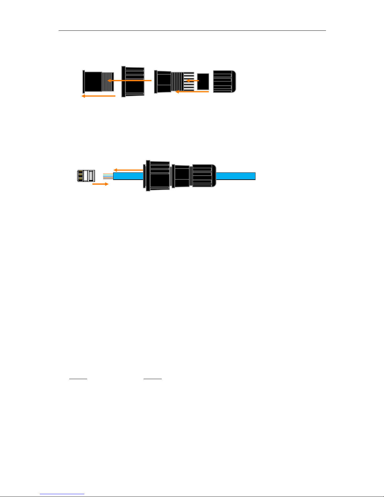
2.4.4 Strain Relief Assembly
Insert A into the large tightening knob (B)
Thread piece C to the end of A. Do not tighten completely until connected to
the WESII LAN port and power is confirmed.
Insert the rubber grommet (D) into the open end of C
Attach E to threaded portion of C. As E is tightened, the grommet will squeeze against
the Ethernet cable jacket. Leave E loose enough for the cable to wiggle slightly.
Slide Ethernet cable through the assembled strain relief unit before crimping on
the RJ45 connector.
Strip cable and configure color code (see section 2.4.5). Use one of the LAN
port weather protection seal stickers – two are provided.
2.4.5 Configuring the Cable
Determine the length of cable that will be required and where the PIM will be located.
Note: The total length of cable from the WESII to the Ethernet device cannot exceed
100m (325 feet), however, the PIM can be located anywhere along the overall 100m
of cable. KBC Networks recommends shielded Ethernet cables for the cable
connecting the PIM to the WESII unit. Any cable exposed to the elements should also
be outdoor rated.
Slide the weatherproof connector over the cable jacket before crimping the
connector. See section 2.4.4 for the strain relief assembly instructions. If
needed, see below for color-code standards to configure the correct type of
Ethernet cable.
Ethernet standard straight-through cable configurations used must be configured to
one of the Ethernet standards (568-A or 568-B) in order for the WESII system to
operate efficiently. Any deviation from one of the two standard configurations can
lead to undesired activity.
Pin out for color codes 568-A and 568-B:
568-A 568-B
1- Green/White 1- Orange/White
2- Solid Green 2- Solid Orange
3- Orange/White 3- Green/White
4- Solid Blue 4- Solid Blue
5- Blue/White 5- Blue/White
6- Solid Orange 6- Solid Green
7- Brown/White 7- Brown/White
8- Solid Brown 8- Solid Brown
B
RJ45
Connector
A C D
E
A B C D E
WESII User Manual
Manual-WESII-Rev1205A
Copyright © KBC Networks 2012 Page 14 of 48 www.kbcnetworks.com
A cable configured with the 568-A color code on one end and the 568-B color code on
the other end is an Ethernet standard crossover cable.
Connect the RJ45 connector into the WESII’s LAN port. Slide the strain relief
back up the cable to the threaded portion on the LAN port of the device and
screw it into the Host/AP or Client and tighten.
Tighten the clamping nut until the Ethernet cable is secured in the connector.
The weatherproof strain relief should be tight to the case but the rubber
grommet opening should remain loose enough for the cable to wiggle slightly.
This will allow for condensation release.
2.4.6 Establishing a Link
For each WESII radio in the system, carry out the following steps:
Verify the antenna alignment and LED status. See section 2.4.3 for applicable
LED activity.
Ensure the green power LED on the PIM is illuminated. The WESII unit’s power
LED should be green provided the cable into the LAN port is seated properly. If
multiple Clients connect to one multipoint Host, verify all Clients are on the
same frequency as the Ptmp Host and pointed in its direction.
Note: The RSSI figures can be used to fine tune alignment see section 2.4.8.
2.4.7 Cable Connections
The following wiring scheme represents the configurations that have been tested and
verified by KBC Networks based on typical Ethernet wiring solutions. Other wiring
configurations could be possible based on the application. A bench test is
recommended to verify the design below.
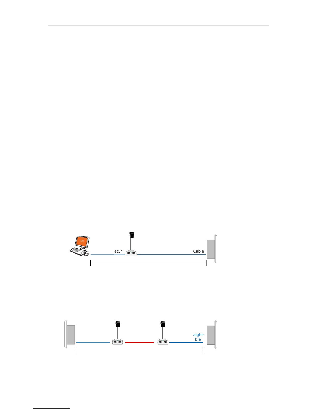
Connecting a WESII unit to an Ethernet Device 2.4.7.1
Note: Must be powered using the supplied power injector, connecting directly to a
PoE switch will not power the WESII.
Connecting Two WESII units in a Relay Format 2.4.7.2
Ethernet Cat5*
Ethernet Straight-
through Cable
Total combined length of cables cannot exceed 100m
24 VDC
Ethernet Crossover
Cable
Ethernet Straight-
through Cable
24 VDC
24 VDC
Ethernet
device
WESII
Ethernet Straight-through Cable
Total combined length of cables cannot exceed 100m
WESII User Manual
Manual-WESII-Rev1205A
Copyright © KBC Networks 2012 Page 15 of 48 www.kbcnetworks.com
Cannot be connected to a PoE port on a switch, the power injector must be
used.
WESII radios cannot communicate via RF link and cable connection
simultaneously.
A crossover cable is not necessary if the two PIMs connect into an Ethernet
switch.
Note: Type of Cat5 configuration may be determined by LAN port of the Ethernet
device. If the port is a 10/100 port, you may require a crossover cable. Most cables
used to connect the WES system are configured using a straight-through color code.
2.4.8 Aligning Directional Antennas
Within the Graphical User Interface (GUI) there are several helpful diagnostic tools.
Following is a short explanation to use the RSSIs for further antenna alignment.
Please see the GUI description in section 3 for further details.
To get to this information, first connect to the RF modules via their respective IP
addresses (see section 3) using a web browser from a laptop connected to the
WESII.
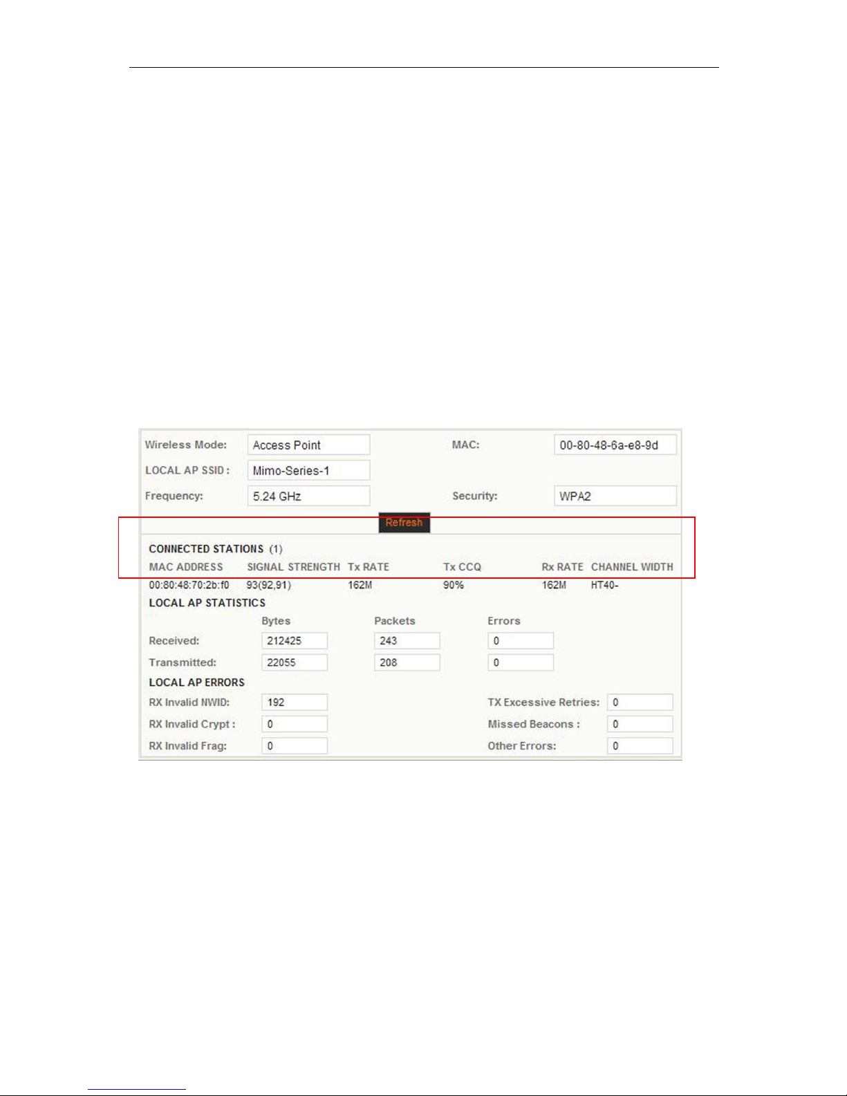
In the screen shot taken from a Ptp Host/AP with one Client connected above, the
section referenced in this portion of the manual is highlighted with the red lined box.
The information needed for the alignment is found under “SIGNAL STRENGTH”. The
RSSI is the number next to the parenthesis. The higher the number, the more signal
strength on the link. Generally this number will be lower than pictured. When
aligning, perform the following procedure:
Loosen the mounting assembly and move the RF Module slightly in a downward
angle. Make the movement no more than a couple of centimeters. Then refresh the
browser three or four times so that the connection can settle in. Note the RSSI and
continue moving the antenna downward, refreshing and noting the RSSI numbers.
Continue until the RSSI decreases. Then in an upward angle, perform the same
 Loading...