


WES2HT
Wireless Ethernet System; High Throughput
WES2HT Series
User Manual

WES2HT User Manual
About This Users’ Guide
Intended Audience
This manual is intended for people who want to configure any of the WES2HT Series. You
will need a basic knowledge of TCP/IP and wireless topology.
Related Documentation
Quick Start Guide
The Quick Start Guide is designed to help you get up and running. It contains basic
information on setting up your individual WES2HT unit.
Technical Specification
The Technical specification is designed to provide you with all the technical specifications
related to the WES2HT units.
KBC Networks’ Website
Please refer to www.kbcnetworks.com for additional support documentation and product
certifications.
Feedback
We welcome all comments, questions and suggestions relating to our User Guides.
Please contact us on:
Technical Department
KBC Networks Ltd
25691 Atlantic Ocean Drive
Suite B3
Lake Forest
CA 92630
Email: techsupport@kbcnetworks.com
Thank you
Manual-WES2HT-Rev1407-1
Copyright © KBC Networks 2013 Page 1 of 142 www.kbcnetworks.com

WES2HT User Manual
Document Conventions
Warnings and Notes
These are how warnings and notes are shown is this Guide.
!Warning!
Warnings tell you about things that could harm you or your device.
Note:
Notes tell you other important information or recommendations.
Example:
Examples are provided to help make the WES2HT set up straight forward.
Syntax Conventions
The WES2HT units may be referred to as the ‘device’, the ‘unit’, the ‘product’, the ‘radios’,
the ‘antenna’ or the ‘system’ in this guide.
<ENTER> denotes enter or return on your keyboard.
<*****> denotes that you need to select that option.
Manual-WES2HT-Rev1407-1
Copyright © KBC Networks 2013 Page 2 of 142 www.kbcnetworks.com

WES2HT User Manual
Safety Warnings
!Warning! For your safety please read the following warning notices and instructions.
Safety, Approvals and Regulatory Domain
Information
Safety Instruction
For your protection, please read and observe all safety instructions before operating this
system and keep this sheet and any additional instructions for future reference.
Installation and Use
OBSERVE WARNINGS: All warnings in the operating instructions should be carefully
followed. Do not make any modifications to the WES2HT unit, Power Injection Module
(PIM), or any other KBC Networks electronic device, as the unit(s) will no longer comply
with legal regulations and therefore void its warranty.
WATER AND MOISTURE: The WES2HT unit is weatherproof provided it is installed in
accordance to the mounting details listed in section 5 below. However, further protection
or housing is suggested for harsh environments, as moisture damage voids its warranty.
The PIMs used in this system are NOT weatherproof. None of the modules in this system
are waterproof and should never be submerged. Severe electrical shock, personal injury
or damage to the equipment may result.
POWER SOURCE: Connect the equipment to a power source only of the type described
on the operating instructions or as marked on the equipment. Excessive or insufficient
current or voltage can cause extended trouble-shooting or even damage that could
negate its warranty. The power supply cable should not be modified/extended due to the
ability to use up to 100m of power over Ethernet cable. In addition, Ethernet cable
running from the PIM to the WEM should be kept separated from high-voltage cables
and/or transformers.
ATTACHMENTS: Use only KBC Networks’ supplied or recommended Power Injection
Modules, Power Supplies, Cat5 Cables and weather seals and plugs.
WHEN NOT IN USE: Unplug the power if the equipment is left unattended or unused
for long periods of time or during lightning storms.
REPLACEMENT PARTS: When replacement parts are required, use only replacement
parts specified by KBC Networks. Unauthorized substitutions may result in damage to
the system and could void the warranty.
Manual-WES2HT-Rev1407-1
Copyright © KBC Networks 2013 Page 3 of 142 www.kbcnetworks.com

WES2HT User Manual
FCC Required Information
Radio Frequency Interference Statement for Class B Digital Devices
This equipment has been tested and found to comply with the limits for an intentional
radiator, pursuant to Part 15, subpart C of the FCC Rules. This equipment generates,
uses and can radiate radio frequency energy. This equipment generates, uses, and can
radiate radio frequency energy. If not installed and used in accordance with the
instructions, it may cause harmful interference to radio communications. The limits are
designed to provide reasonable protection against such interference in residential
situations. However, there is no guarantee that interference will not occur in a particular
installation. If this equipment does cause interference to radio or television reception,
which can be determined by turning the equipment on and off, the user is encouraged to
try to correct the interference but on or more of the following measures:
Re-orientate or relocate the receiving antenna of the affected radio or television.
Increase the separation between the equipment and the affected rec e i v e r.
Connect the equipment and the affected receiver to power outlets on separate
circuits.
Consult the dealer or an experienced radio/TV technician for assistance.
Shielded cables must be used with this unit to ensure compliance with Class B FCC
limits. Changes or modifications to this unit not expressly approved by the party
responsible for compliance could void the user’s authority to operate the equipment.
Changes or modifications not expressly approved by KBC could void the user’s authority
to operate the equipment.
FCC Power Output Restrictions
The FCC does not require licensing to implement this device. License-free operation in
the industrial, scientific and medical band is documented in FCC Rules Part 15.247. It is
the responsibility of the individuals designing and implementing the radio system to
ensure compliance with any pertinent FCC Rules and Regulations. This device must be
professionally installed.
Exposure to Radio Frequency Fields
The WES2HT is designed to operate on the 5 GHz frequency band with up to 50 Watts
EIRP maximum transmit power. This level of RF energy is above the Maximum
Permissible Exposure (MPE) levels specified in FCC OET65:97-01. The following
precautions must be taken during installation of this equipment:
The installed antenna must not be located in a manner that allows exposure of
the general population to the direct beam path of the antenna at a distance less
than 20cm. Installation on towers, masts, or rooftops not accessible to the
general population is recommended or alternatively mount the antenna in a
manner that prevents any personnel from entering the area within 20cm from the
front of the antenna.
It is recommended that the installer place radio frequency hazard warnings signs
on the barrier that prevents access to the antenna.
During installation and alignment of the antenna, do not stand in front of the
antenna assembly.
Manual-WES2HT-Rev1407-1
Copyright © KBC Networks 2013 Page 4 of 142
www.kbcnetworks.com

WES2HT User Manual
During installation and alignment of the antenna, do not handle or touch the front
of the antenna.
These simple precautions must be taken to prevent general population and installation
personnel from exposure to RF energy in excess of specified MPE levels.
Industry Canada Restrictions
IC ID# 7849A-N523ESD
This Class A digital apparatus complies with Canadian ICES-003. To reduce potential
radio interference to other users, the antenna type and its gain should be so chosen that
the equivalent isotropically radiated power (E.I.R.P.) is not more than that permitted for
successful communication. This device complies with Industry Canada license-exempt
RSS standard(s).
Operation is subject to the following two conditions:
This device may not cause interference, and
This device must accept any interference, including interference that may cause
undesired operation of the device.
Cet appareil numérique de la classe A est confrome à la norme NMB-003 Canada. Pour
réduire le risque d’interférence aux autres utilisateurs, le type d’antenne et son gain
doivent être choisies de façon que la puissance isotrope rayonnée équivalente (PIRE) ne
dépasse pas ce qui est nécessaire
pour une communication réussie. Cet appareil est conforme à la norme RSS Industrie
Canada exempts de licence norme(s). Son fonctionnement est soumis aux deux
conditions suivantes:
17 Compliance
Cet appareil ne peut pas provoquer d’interférences et
Cet appareil doit accepter toute interférence, y compris les interférences qui peuvent
causer un mauvais fonctionnement du dispositif.
RF Exposure Warning
The antennas used for this transmitter must be installed to provide a separation distance
of at least 37.2 cm from all persons and must not be located or operating in conjunction
with any other antenna or transmitter.
Les antennes utilisées pour ce transmetteur doivent être installé en considérant une
distance de séparation de toute personnes d'au moins 37.2 cm et ne doivent pas être
localisé ou utilisé en conflit avec tout autre antenne ou transmetteur.
Manual-WES2HT-Rev1407-1
Copyright © KBC Networks 2013 Page 5 of 142
www.kbcnetworks.com

WES2HT User Manual
CE Regulatory Statement
Class B ITE:
This is a Class B product. In a domestic environment this product may cause radio
interference in which case the user may be required to take adequate measures.
Declaration of Conformity:
KBC declares the following:
Product Name: WES2HT
Model No.: 802.11n Station conforms to the following Product Standards:
This device complies with the Electromagnetic Compatibility Directive (89/336/EEC)
issued by the Commission of the European Community. Compliance with this directive
implies conformity to the following European Norms (in brackets are the equivalent
international standards.)
Electromagnetic Interference (Conduction and Radiation): EN 55022 (CISPR 22)
Electromagnetic Immunity: EN 55024 (IEC61000-4-2, 3, 4, 5, 6, 8, 11)
Low Voltage Directive: EN 60 950: 1992+A1: 1993+A2: 1993+A3: 1995+A4:
1996+A11: 1997.
CE Mark: following the provisions of the EC directive.
KBC also declares that:
The wireless card in this product complies with the R&TTE Directive (1999/5/EC) issued
by the Commission of the European Community. Compliance with this directive implies
conformity to the following:
EMC Standards: CE: EN 300 328-2, EN 300 826 (EN 301 489-17) EN 301 893.
CE marking on this product represents the product is in compliance with all directives
that are applicable to it.
This equipment may be operated in the following countries:
Great Britain and Northern Ireland, Austria, Belgium, Denmark, Finland, France,
Germany, Ireland, Italy, Netherlands, Norway, Portugal, Romania, Switzerland, Sweden
Installer Compliance Responsibility
Devices must be professionally installed and it is the professional installer's responsibility
to make sure the device is operated within local country regulatory requirements.
Dynamic Frequency Selection (DFS) & Transmit Power Control (TPC):
DFS and TPC are requirements of the ETSI standard EN301 893 V1.5.1, the European
Union’s harmonized radio standard for unlicensed devices operating in the 5150 – 5350
MHz and 5470 – 5725 MHz frequency bands. Radar detection is required when operating
on channels whose nominal bandwidth falls partly or completely within the frequency
ranges 5250 MHz to 5350 MHz or 5470 MHz to 5725 MHz. In addition devices using the
5600 – 5650 MHz band are subject to a 10 minute Channel Availability Check (CAC).
The following table shows how this can affect connection times for certain frequencies:
Manual-WES2HT-Rev1407-1
Copyright © KBC Networks 2013 Page 6 of 142 www.kbcnetworks.com

WES2HT User Manual
Frequency (MHz)
Channel Bandwidth
5MHz
10MHz
20MHz
20/40MHz
5500
2 mins
2 mins
2 mins
2 mins
5505
2 mins
5510
2 mins
2 mins
5515
2 mins
5520
2 mins
2 mins
2 mins
5525
2 mins
5530
2 mins
2 mins
5535
2 mins
5540
2 mins
2 mins
2 mins
2 mins
5545
2 mins
5550
2 mins
2 mins
5555
2 mins
5560
2 mins
2 mins
2 mins
5565
2 mins
5570
2 mins
2 mins
5575
2 mins
5580
2 mins
2 mins
2 mins
10 mins
5585
2 mins
5590
2 mins
2 mins
5595
2 mins
5600
10 mins
10 mins
10 mins
5605
10 mins
5610
10 mins
10 mins
5615
10 mins
5620
10 mins
10 mins
10 mins
10 mins
5625
10 mins
5630
10 mins
10 mins
5635
10 mins
5640
10 mins
10 mins
10 mins
5645
10 mins
5650
10 mins
10 mins
5655
2 mins
5660
2 mins
2 mins
2 mins
2 mins
5665
2 mins
5670
2 mins
2 mins
5675
2 mins
5680
2 mins
2 mins
2 mins
5685
2 mins
5690
2 mins
2 mins
5695
2 mins
Manual-WES2HT-Rev1407-1
Copyright © KBC Networks 2013 Page 7 of 142 www.kbcnetworks.com

WES2HT User Manual
5700
2 mins
2 mins
2 mins
Environmental Restrictions of Wireless Devices
KBC products are engineered to the highest standards and designed to work in a variety
of wireless applications and environments. A wireless environment includes the site in
which the product is installed, the installation including power and cabling as well as any
extra materials that might be necessary to complete the wireless project. Due to the fact
that environments and installations differ from site to site, KBC cannot control the
variables required to ensure an ideal environment. Therefore, it is not possible to
guarantee a successful application based on a drawing, application note, distance
calculation, quote or other type of material that KBC may provide. Should a quote,
drawing, etc. be made available, it is based on the performance of the WES2HT product
in an ideal environment with clear line-of-sight, absence of radio frequency (RF)
interference and/or frequency multi-path reflection. Therefore, KBC cannot be held
responsible should the products not operate as desired or should additional products be
required to complete a project. In addition, should a particular environment restrict the
usage of the WES2HT in any way, KBC offers a thirty (30) day return policy from date of
shipment to the original purchaser if goods are returned in an ‘as new’ condition.
Manual-WES2HT-Rev1407-1
Copyright © KBC Networks 2013 Page 8 of 142 www.kbcnetworks.com

WES2HT User Manual
RoHS/WEEE Compliance Statement
European Directive 2002/96/EC requires that the equipment bearing this symbol on the
product and/or its packaging must not be disposed of with unsorted municipal waste.
The symbol indicates that this product should be disposed of separately from regular
household waste streams. It is your responsibility to dispose of this and other electric
and electronic equipment via designated collection facilities appointed by the
government or local authorities. Correct disposal and recycling will help prevent potential
negative consequences to the environment and human health. For more detailed
information about the disposal of your old equipment, please contact your local
authorities, waste disposal service, or the shop where you purchased the product.
Instruction of Disassembly
Note: disassembling or opening of the WES2HT unit voids warranty.
Instruction of Disassembly of KBC Product (For EU Directive 2002/95/EECWEEE)
Tools required:
No. 1 Phillips screwdriver
No. 2 Phillips screwdriver
Steps for disassembly:
Remove Serial Label adhesive
Remove cover screws attaching top cover to radio module cavity.
Remove tightening screws for printed circuit board (PCB).
Take out all PCBs.
Note: When a product reaches the end of its life – return to KBC.
Manual-WES2HT-Rev1407-1
Copyright © KBC Networks 2013 Page 9 of 142 www.kbcnetworks.com

WES2HT User Manual
General Public License Statement
You may have received from KBC Networks products that contained – in part – free
software (software licensed in a way that ensures your freedom to run, copy, distribute,
study, change and improve the software). Such products include the WES2HT Series of
products.
As part of these products, KBC Networks may have distributed to you hardware and/or
software that contained a version of free software programs developed by the Free
Software Foundation, a separate not-for-profit organization without any affiliation to KBC
Networks. See http://www.gnu.org/philosophy/free-sw.html for more details. If KBC
Networks distributed any portions of these free software programs to you, you were
granted a license to that software under the terms of either the GNU General Public
License or GNU Lesser General Public License (“License”, copies of which are available
from http://www.gnu.org/licenses/licenses.html). The Licenses allow you to freely copy,
modify and redistribute that software without any other statement or documentation
from us.
For at least one (1) year from the date of distribution of the applicable product or
software, KBC Networks will provide to anyone who contacts us at the contact
information provided below, for a charge of no more than our cost of physically
performing source code distribution, a complete machine-readable copy of the complete
corresponding source code for the free software programs used in the version of the
programs that we distribute to you. The cost will be free if the delivery medium of the
machine-readable copy is through the Internet.
Contact information:
Email: techsupport@kbcnetworks.com
Tel: 949.297.4930
Address: 25691 Atlantic Ocean Drive Lake Forest, CA 92630
We do ask for your understanding regarding expected delivery timelines:
We will reply within 7 working days once the request has been made through
email/telephone.
The default version sent will be the latest that we used in the firmware/programs.
Note: it may take longer if an older version is requested. The waiting time will not
exceed 2 weeks.
Manual-WES2HT-Rev1407-1
Copyright © KBC Networks 2013 Page 10 of 142 www.kbcnetworks.com

WES2HT User Manual
TABLE OF CONTENTS
ABOUT THIS USERS GUIDE…………………………………………………………………………………………1
Intended Audience…………………………………………………………………………………………………………………………..….…….…1
Related Documentation…………………………………………………………………………………………………………………..……………1
DOCUMENT CONVENTIONS……………………………………………………………………………………….2
Warnings and Notes………………………………………………………………………………………………………………………...………….2
Syntax Conventions ……………………………………………………………………………………………………………………………………..2
SAFETY WARNINGS……………………………………………………………………………………………………3
SAFETY, APPPROVALS AND REGULATORY DOMAIN INFORMATION………………………….3
Safety Instruction………………………………………………………………………………………………………………………….…………….3
FCC Required Information……………………………………………………………………………………………….…………………………..4
Industry Canada Restrictions……………………………………………………………………………………………………….……………...5
CE Regulatory Statement…………………………………………………………………………………………………….………………………6
Environmental Restrictions of Wireless Devices…………………………………………………………………….…………………….8
ROHS/WEEE COMPLIANCE STATEMENT…………………………………………………………………….9
Instructions of Disassembly……………………………………………………………………………………………………..…………………..9
GENERAL PUBLIC LICENSE STATEMENT………………………………………………………………….10
1 OVERVIEW…..………………………………………………………………….……………………………14
1.1 Introduction………………………………………………………………………………………………………………………………………14
1.2 General Technical Specification…………………………………………………………………………..…………………………….15
2 TYPICAL CONFIGURATIONS…………………………………………………….……………..…..17
2.1 Point-to-point…………………………………………………………………………………………………………………………………….17
2.2 Point-to-multipoint…………………………………………………………………………………………………………………………….18
2.3 Relay………………………………………………………………………………………………………………………………………………….19
2.4 Wi-Fi Access Point………………………………………………………………………………………………………………………………19
2.5 Mixed systems – WES2HT & MESH2HT (or MESHII) ….………………………………………………………………….…...20
3 ANTENNA OPTIONS……………………………………………………………………………………….21
3.1 Omni-directional antennas………………………………………………………………………………………………………………..21
3.2 Integrated directional antenna options……………………………………………………………………………………………..21
3.3 External directional patch antenna options………………………………………………………………………………………..22
4 POINT-TO-POINT KITS…………………………………….……………………….………………….23
5 MOUNTING INSTRUCTIONS…………………………………………………………………………..24
5.1 Pole and wall-mount for integrated directional WES2HT units……………………………………………………………24
Manual-WES2HT-Rev1407-1
Copyright © KBC Networks 2013 Page 11 of 142 www.kbcnetworks.com

WES2HT User Manual
6 CONNECTIONS……………………………………………………………………………….……………..26
6.1 Physical Connections…………………..…………………………………………………….……………………………………………..26
6.2 Power Connections…………………………………………………………………………………………………………………………..27
7 LED STATUS……………………………………………….………………………………………………….28
8 CABLE ASSEMBLY………………………………………………………………………………………….29
8.1 Strain Relief Assembly…………………………………………………………………..……………………..……….……….……….29
8.2 Configuring the Cable………………………………………………………………………………………………………………..…….29
8.3 Disconnecting the Cable from the External LAN Port……………………………………………………………….………30
9 SETTING UP A BASIC LINK…………………………………………………………………………..31
9.1 Setting up a basic point-to-point link – United States & Canada…………………………………………….………..32
9.2 Setting up a basic point-to-point link – EMEA………………………….…………………………………………….………..40
9.3 Setting up a basic point-to-point link – Australia…………………….……………………………….…………….………..54
9.4 Setting up a basic point-to-multipoint link – United States & Canada………………………………...….………..62
9.5 Setting up a basic point-to-multipoint link – EMEA………………………….……………………………………….……..71
9.6 Setting up a basic point-to-point link – Australia…………………….……………………………………….…….………..84
10 INSTALLING ON SITE…………………………………………………………………………………….91
10.1 Line-of-sight…………………………………………………………………………………………………………………….………..…...91
10.2 Spacing required when mounting WES2HT units……………………………………………………………………………..93
10.3 Cable lengths when installing WES2HT units………………………………………………………………..…….……………94
10.4 Aligning the WES2HT units……………………………………………………………………………………….………………………95
10.5 Configuring IP addresses on a site…………………………………………………………………………………………………….95
10.6 Replacing/adding a WES2HT Module from/to the existing application…………………………………………….96
11 GRAPHICAL USER INTERFACE………………………………………………………………………97
11.1 Connecting to the WES2HT GUI using a PC……………………………………………………..………………….…………..97
11.2 WES2HT Menu Options……………………………………………………………………………………………………..…….…….99
12 TROUBLESHOOTING……………………………………………………………………………………137
12.1 Visual Inspection……………………………………………………………………………………………..……………………………..137
12.2 Test Cable Connections…………………………………………………………………………………………………………………...137
12.3 GUI Tools…………………………………………………………………………………………………………………………………………137
12.4 Hard reset to defaults……………………………………………………………………………………………………………………..138
12.5 Contact KBC Technical Assistance…………………………………………………………………………………………………….139
13 WARRANTY………………………………………………………………………………………………….140
Manual-WES2HT-Rev1407-1
Copyright © KBC Networks 2013 Page 12 of 142 www.kbcnetworks.com

WES2HT User Manual
1. Overview
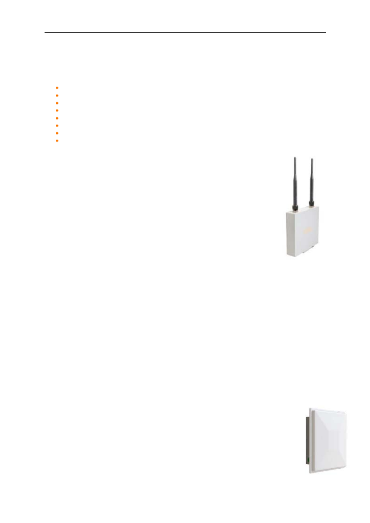
1.1 Introduction
This manual covers all the functions of the products that form KBC Networks’ WES2HT
Series. The WES2HT High Throughput Wireless Ethernet System is a wireless
transmission system that provides a cable less transmission path for an Ethernet
channel. They are designed for use in a wide range of operating temperatures in nonenvironmentally conditioned, outdoor applications. The primary function of the system is
to replace Ethernet cables where it is not practical or cost-effective or where it is beyond
distance limitations. WES2HT has been specifically designed to transmit constant
streaming video but can also be used to send and receive standard Ethernet data
packets and in some cases, with certain WES2HT models, to operate as a WiFi Access
Point. The units can be configured as a long range point-to-point wireless bridge or as a
point-to-multipoint receiving antenna communicating to numerous transmitting
Client/Station devices. This manual covers all operations and functions of the point-topoint and point-to-multipoint systems.
1.1.1. WES2HT
The KBC WES2HT Series is a wireless transmission system that operates in the license
free 2.4GHz & 5GHz bands and also in the 4.9GHz Public Safety band (only available in
the US). The units are available as PoE or non-PoE with a range of antennas to suit
applications. The units will support useable throughput of up to 230Mbps (400Mbps
aggregate). WES2HT requires CAT6 or above (Gigabit Ethernet Cable).
Manual-WES2HT-Rev1407-1
Copyright © KBC Networks 2013 Page 13 of 142 www.kbcnetworks.com

WES2HT User Manual
WES2HT Specification
Standards
IEEE Standards
IEEE 802.3 10BASE-T
IEEE 802.3u 100BASE-TX
IEEE 802.3x Full Duplex
IEEE 802.11a 5GHz
IEEE 802.11b 2.4GHz
IEEE 802.11g 2.4GHz
IEEE 802.11y 4.9GHz US Public Safety
IEEE 802.11n MIMO
IEEE 802.11h ETSI DFS & TPC
IEEE 802.3af
Radio
Frequency (MHz)
USA & Canada:
2412 - 2472
4940 - 4990
5745 – 5825
Europe:
2412 - 2472
5500 - 5700
Frequency Operation
Auto-select
User static selectable
Dynamic Frequency Selection (ETSI DFS)
Power Output
23dBm max1
Transmit Power Control (ETSI TPC)
Channel Capacity
Selectable 5, 20 or 40MHz
Modulation
OFDM
Antennas
2dBi/5dBi (2.4GHz/4.9GHz & 5GHz)
Omni-directional
9dBi (4.9GHz & 5GHz)
Directional integrated patch
Dual polarization
Beamwidth:
Azimuth: Horizontal 65°, Vertical 65°
Elevation: Horizontal 33°, Vertical 33°
11dBi (2.4GHz)
Directional integrated patch
Dual polarization
Beamwidth
Azimuth: Horizontal 56°, Vertical 62°
Elevation: Horizontal 38°, Vertical 26°
17dBi (4.9GHz & 5GHz)
Directional integrated patch
Dual polarization
Beamwidth:
General Technical Specification
1
Territory specific.
2
Assumes an ideal environment with maximum signal rates & within receive
sensitivity specification.
Manual-WES2HT-Rev1407-1
Copyright © KBC Networks 2013 Page 14 of 142 www.kbcnetworks.com

WES2HT User Manual
Azimuth: Horizontal 30°, Vertical 33°
Elevation: Horizontal 17°, Vertical 17°
System
Data throughput2
(max values – limited by 10/100 port)
HT5 HT20 HT40
17Mbps 130Mbps 230Mbps
Latency
< 10 mS
Power
Power input (supplied by PIM)
24Vdc, 500mA
Reverse voltage protected
Power method (non-PoE WES2HT)
Passive PoE
Power method (PoE WES2HT)
IEEE 802.3af (PD)
PoE cable spec
100m on 24AWG Cat5/5e/6/6e
Mechanical
Casing
IP66
Dimensions (Patch L x W x D)
245mm x 245mm x 76mm
9.625” x 9.625” x 3”
Weight
420g
15oz
Installation
Wall-mount or pole-mount
Environmental
Operating Temperature
-40° ~ +74°C / -40° ~ +165°F
Storage Temperature
-40° ~ +90°C / -40° ~ +194°F
Operating Humidity
5% to 95% non-condensing
Connectors
10/100/1000 Electrical
1 x RJ45
Approvals
FCC Part 15 subpart C
Class B
IC ID# 7849A-N523ESD
CE
Class B
EN 55024 (IEC61000-4-2,3,4,5,6,8,11)
Electromagnetic Immunity
EN 55022 (CISPR 22)
Electromagnetic Interference (Conduction
and Radiation)
EN 60 950: 1992+A1; 1993+A2;
1995+A4; 1996+A1; 1997
Low Voltage Directive
EN 300 328-2
EN 300 826
EN 301 489-17
EN 301 893
R&TT Directive (1999/5/EC)
2
Assumes an ideal environment with maximum signal rates & within receive
sensitivity specification.
Manual-WES2HT-Rev1407-1
Copyright © KBC Networks 2013 Page 15 of 142 www.kbcnetworks.com
WES2HT User Manual
2. Typical Configurations
The WES2HT units are available to work in the following configurations:
Point-to-point
Point-to-multipoint
Relay
Wi-Fi Access Point
Mixed systems
o WESII / WES2HT
o WESII or WES2HT / MESH2HT
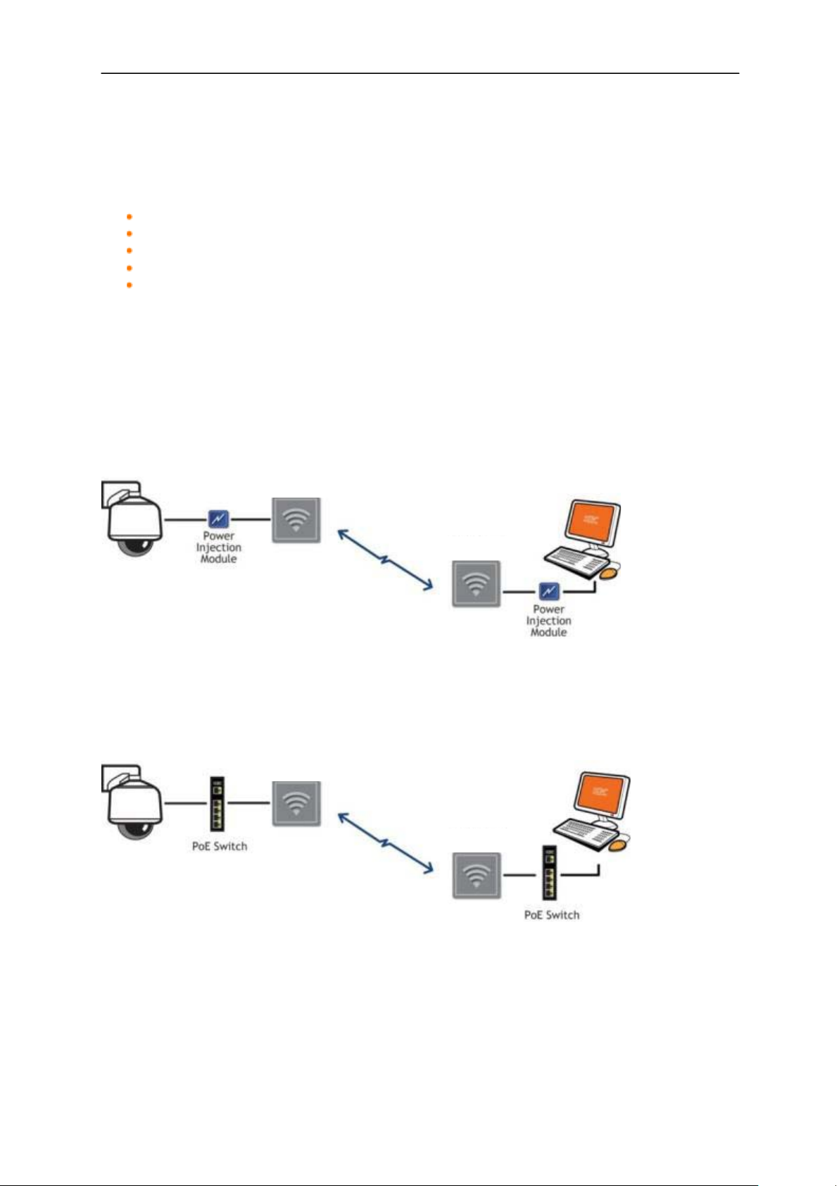
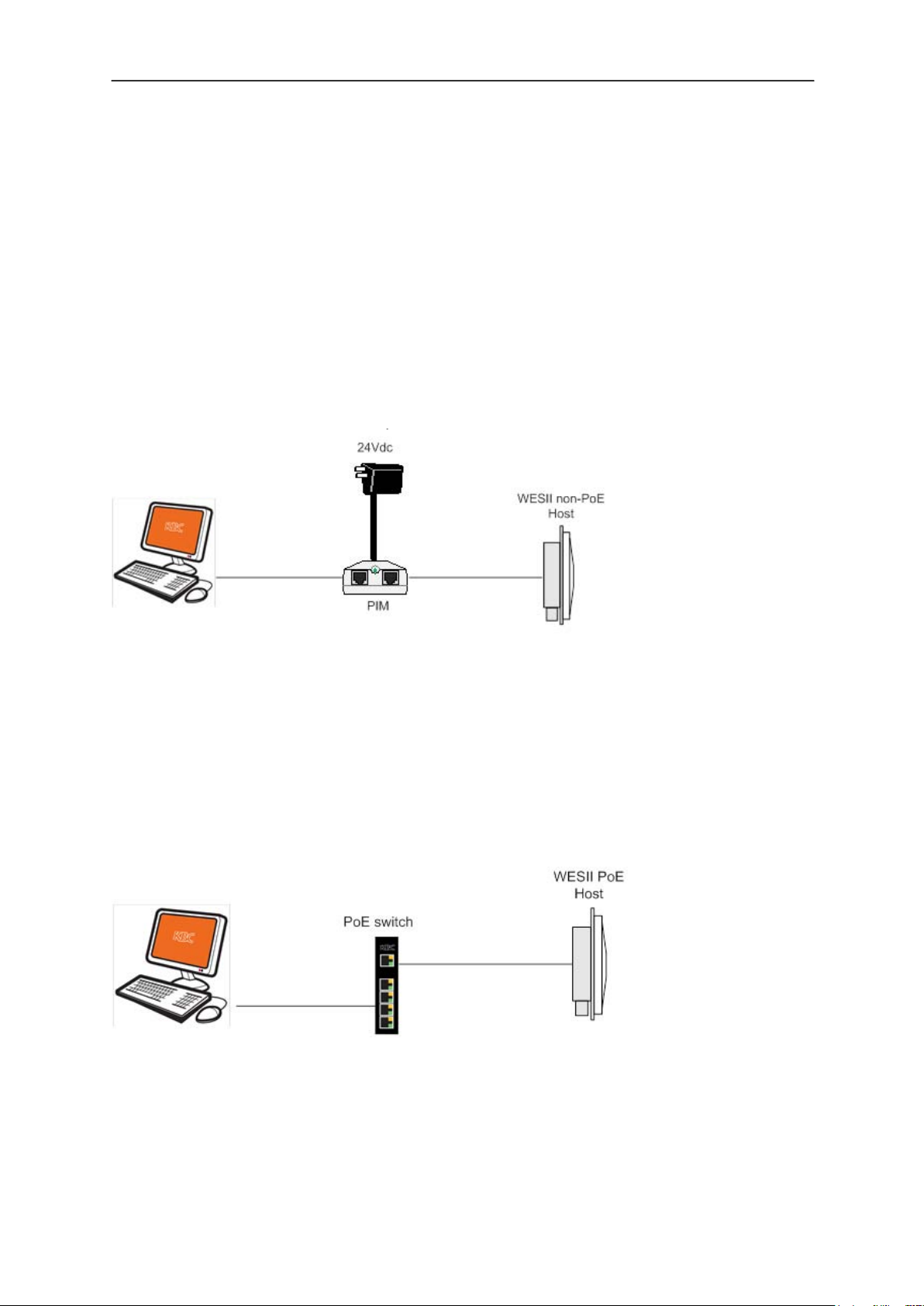
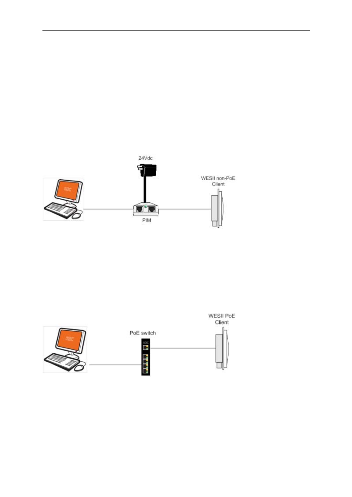
2.1 Point-to-Point
2.1.1 Non-PoE WES2HT
WES2HT Client
WES2HT Host
Note: The drawings above and below show the parts that come in a standard WES2HT-
KT (i.e., WES2HT Host and Client and accessories). The power supplies and power
injectors in the kit will only power the WES2HT and will not power the camera or any
other device other than the WES2HT units.
2.1.2 PoE WES2HT
WES2HT Client
WES2HT Host
Note: The system is capable of being powered by PoE or via the passive power injector
(PIM) and power supply included with the product. In essence, there is only one version
of the system but it can be powered via the PIM if there is no PoE switch available or via
an IEEE 802.3af PSE device.
Manual-WES2HT-Rev1407-1
Copyright © KBC Networks 2013 Page 16 of 142
www.kbcnetworks.com
WES2HT User Manual
WES2HT Client
WES2HT Host
WES2HT Client
WES2HT Client
High Megapixel Camera
WES2HT Client
WES2HT Host
WES2HT Client
WES2HT Client
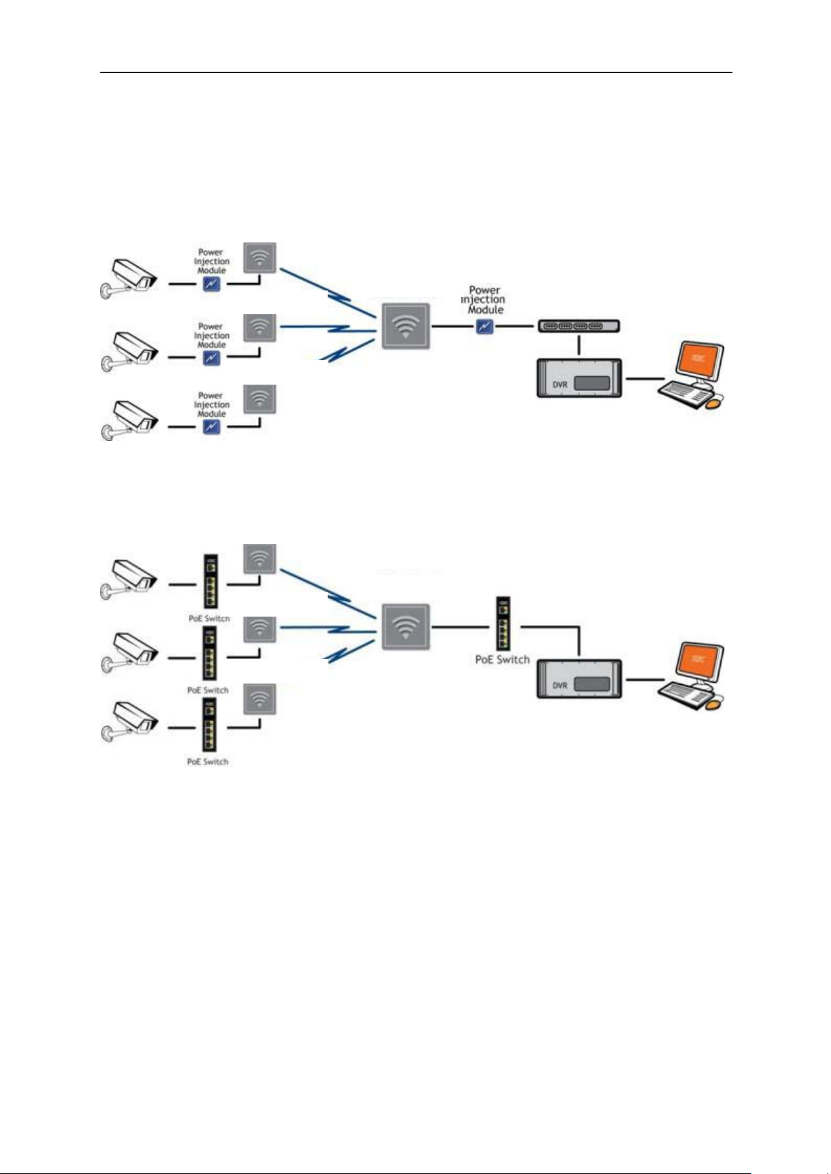
2.2 Point-to-multipoint
2.1.1. Non-PoE WES2HT
2.1.2. PoE WES2HT
Note: Switches must be gigabit POE or gigabit POE+
Note: The system is capable of being powered by PoE or via the passive power injector
(PIM) and power supply included with the product. In essence, there is only one version
of the system but it can be powered via the PIM if there is no PoE switch available or via
an IEEE 802.3af PSE device.
Manual-WES2HT-Rev1407-1
Copyright © KBC Networks 2013 Page 17 of 142 www.kbcnetworks.com
WES2HT User Manual
WES2HT Host #1
WES2HT Client #2
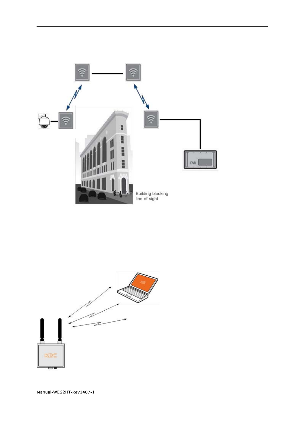
2.3 Relay
WES2HT Client #1
WES2HT Host # 2
2.4 Wi-Fi Access Point
Note: Only multipoint Hosts are able to operate as a Wi-Fi AP (i.e., WES2HT-AB-Ax /
WES2HT-AB-Bx or WES2HT-DB-Ax / WES2HT-DB-Bx -- “x” is a place holder for the
actual indicator used in the complete model number to identify the global type of power
supply included in the kit)
Manual-WES2HT-Rev1407-1
Copyright © KBC Networks 2013 Page 18 of 142
www.kbcnetworks.com
WES2HT User Manual
WES2HT MP Host
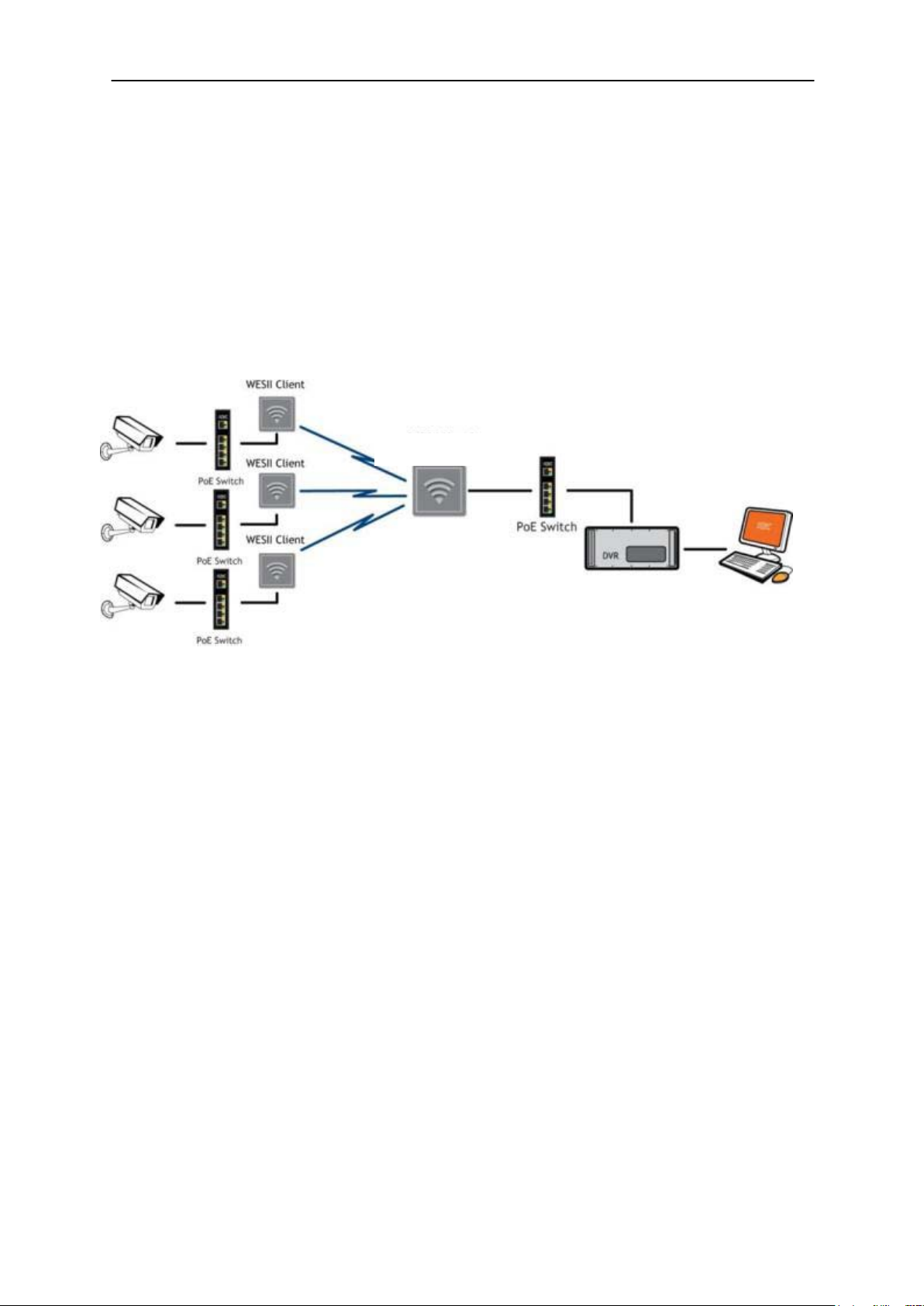
2.5 Mixed systems – WES2HT & MESH2HT (or MESHII)
In many wireless designs there are multiple transmitters sending to one common
receiver. Often the amount of throughput coming into the transmitter is less than
99Mbps so the standard WESII series could be used on the transmit side. On the receive
side, however, the overall throughput coming into the receiver may exceed 99Mbps and
therefore need the HT multipoint host. In the drawing below, assume that the camera
icon represents numerous cameras and/or high megapixel but the total amount of
throughput at each transmit site will never exceed 99Mbps. The diagram also assumes
that the amount of throughput at the receive Host site is more than 99Mbps but less
than 230Mbps.
Note: Switch at the Host receive side must be gigabit (POE optional)
Manual-WES2HT-Rev1407-1
Copyright © KBC Networks 2013 Page 19 of 142 www.kbcnetworks.com
WES2HT User Manual
3. Antenna Options
The WES2HT units are available with the following antennas:
2dBi/5dBi dual rated omni-directional antenna for 2.4GHz/4.9GHz & 5GHz
11dBi/13dBi dual rated omni-directional antenna for 2.4GHz/4.9GHz & 5GHz
9dBi integral patch antenna for 4.9GHz & 5GHz operation
11dBi integral patch antenna for 2.4GHz operation
17dBi integral patch antenna 4.9GHz 5GHz operation
9dBi external patch antenna for 4.9GHz & 5GHz operation
11dBi external patch antenna for 2.4GHz operation
17dBi external patch antenna for 4.9GHz & 5GHz operation
3.1 Omni-directional options
3.1.1 2dBi/5dBi
This is a dual frequency rated omni-directional antenna for 2.4GHz,
4.9GHz & 5GHz operation. At 2.4GHz the antenna has a gain of
2dBi and at 4.9GHz & 5GHz the antenna has a gain of 5dBi. The
beamwidth of the antenna is 360°. The WES2HT unit will need two
of these antennae but no connecting cable is necessary.
3.1.1 11dBi/13dBi
This is a dual frequency rated omni-directional high gain antenna
option for 2.4GHz, 4.9GHz & 5GHz operation. At 2.4GHz the antenna has a gain of 11dBi
and at 4.9GHz & 5GHz the antenna has a gain of 13dBi. The beamwidth of the antenna
is 360°. This antenna has two N-Connectors so only one antenna is needed per WES2HT
unit. Each antenna ships with two 1m connecting cables enabling one omni antenna to
connect to both antenna ports on the WES2HT unit.
Note: This antenna is not included in any of the standard WES2HT model kits. It is
designed to be an available high gain omni option when the included 5dBi antennae will
not achieve the necessary distances and connection signal strengths.
3.2 Integrated directional patch antenna options
3.2.1 9dBi
This is an integral directional patch antenna option for 4.9GHz & 5GHz operation. The
antenna is dual polarized. The beamwidth is:
Azimuth: Horizontal 65°, Vertical 65°; Elevation: Horizontal 33°, Vertical 33°
3.2.2 11dBi
This is an integral directional patch antenna option for 2.4GHz operation. The
antenna is dual polarized. The beamwidth is:
Azimuth: Horizontal 56°, Vertical 62°; Elevation: Horizontal 38°, Vertical 26°
Manual-WES2HT-Rev1407-1
Copyright © KBC Networks 2013 Page 20 of 142
www.kbcnetworks.com

WES2HT User Manual
3.2.3 17dBi
This is an integral directional patch antenna option for 4.9GHz & 5GHz operation. The
antenna is dual polarized. The beamwidth is:
Azimuth: Horizontal 30°, Vertical 33°
Elevation: Horizontal 17°, Vertical 17°
3.3 External directional patch antenna options
External antennas can be attached to the antenna ports on the external antenna chassis
and are provided with 2 x 1m cables. See section 6.1.2.
3.3.1 9dBi
This is an external directional patch antenna option for 4.9GHz & 5GHz operation, part
number PAT5M-9. The antenna is supplied as a separate unit that contains 1 x 9dBi
patch antenna and 2 x 1m cables. The antenna is dual polarized. The
beamwidth is:
Azimuth: Horizontal 65°, Vertical 65°
Elevation: Horizontal 33°, Vertical 33°
3.3.2 11dBi
This is an external directional patch antenna option for 2.4GHz operation,
part number PAT2M. The antenna is supplied as a separate unit that contains
1 x 11dBi patch antenna and 2 x 1m cables. The antenna is dual polarized.
The beamwidth is:
Azimuth: Horizontal 56°, Vertical 62°
Elevation: Horizontal 38°, Vertical 26°
3.3.3 17dBi
This is an external directional patch antenna option for 4.9GHz & 5GHz operation, part
number PAT5M. The antenna is supplied as a separate unit that contains 1 x 17dBi patch
antenna and 2 x 1m cables. The antenna is dual polarized. The beamwidth is:
Azimuth: Horizontal 30°, Vertical 33°
Elevation: Horizontal 17°, Vertical 17°
Manual-WES2HT-Rev1407-1
Copyright © KBC Networks 2013 Page 21 of 142
www.kbcnetworks.com

WES2HT User Manual
Part number
Description
Contents
WES2HT-KT
5GHz, point-to-point 17dBi kit
1 x 5GHz WES2HT-AA-Cx 17dBi Singlepoint Host; 1 x 5 GHz WES2HT-AC-Cx
17dBi Client; 2 x Gigabit LAN power
injectors; 2 x 24VDC Power Supplies; 2 x
pole/wall mounting assemblies.
WES2HT-KT-9
5GHz, point-to-point 9dBi kit
1 x 5GHz WES2HT-AA-Bx 9dBi Singlepoint Host; 1 x 5 GHz WES2HT-AC-Bx
9dBi Client; 2 x Gigabit LAN power
injectors; 2 x 24VDC Power Supplies; 2 x
pole/wall mounting assemblies
WES2HT-KT-49
4.9GHz, point-to-point kit
Included in the WES2HT-KT-49 is all that
is included in the WES2HT-KT but the
radios are 4.9GHz as opposed to 5GHz.
This system operates on the Public
Safety band and is approved by
FCC/IC to be used by first response
only. It remains the responsibility of the
user to abide by FCC or IC requirements.
WES2HT-KT-P8
5GHz, point-to-point kit with
8 port PoE+ Gig switch &
narrow temperature range
PSU
Included in the WES2HT-KT-P8 is all that
is included in the WES2HT-KT as well as:
1 x ESUG8P-D Gigabit Switch + 1 x DRP480-48 Power Supply
WES2HT-KT-P8T
5GHz, point-to-point kit with
8 port PoE+ Gig switch &
extended temperature range
PSU
Included in the WES2HT-KT-P8T is all that
is included in the WES2HT-KT as well as:
1 x ESUG8P-D Gigabit Switch + 1 x SDR480-48 Power Supply
4. Point-to-point Kits
There are a number of WES2HT point-to-point kits that are available, details are below:
Note: In the model numbers referenced above “x” is a place holder for the actual
indicator used in the complete model number to identify the global type of power supply
included in the kit.
Manual-WES2HT-Rev1407-1
Copyright © KBC Networks 2013 Page 22 of 142 www.kbcnetworks.com
WES2HT User Manual
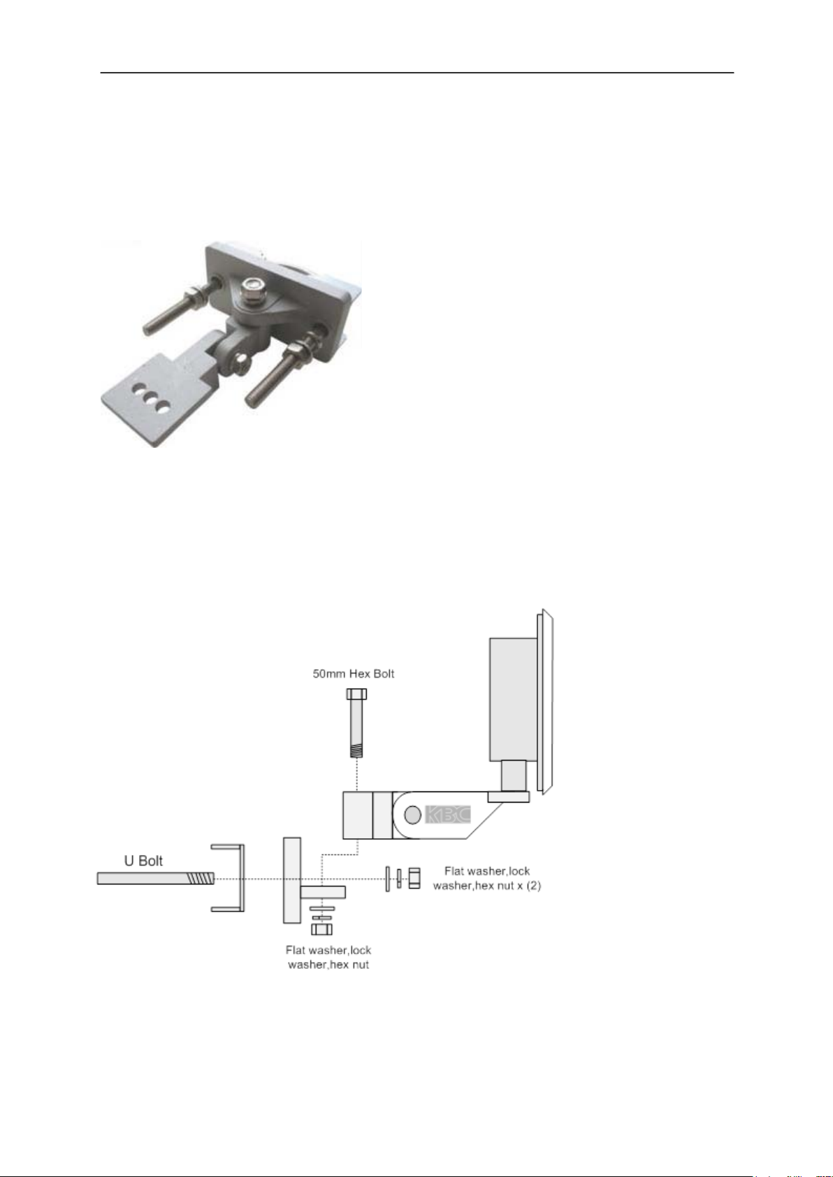
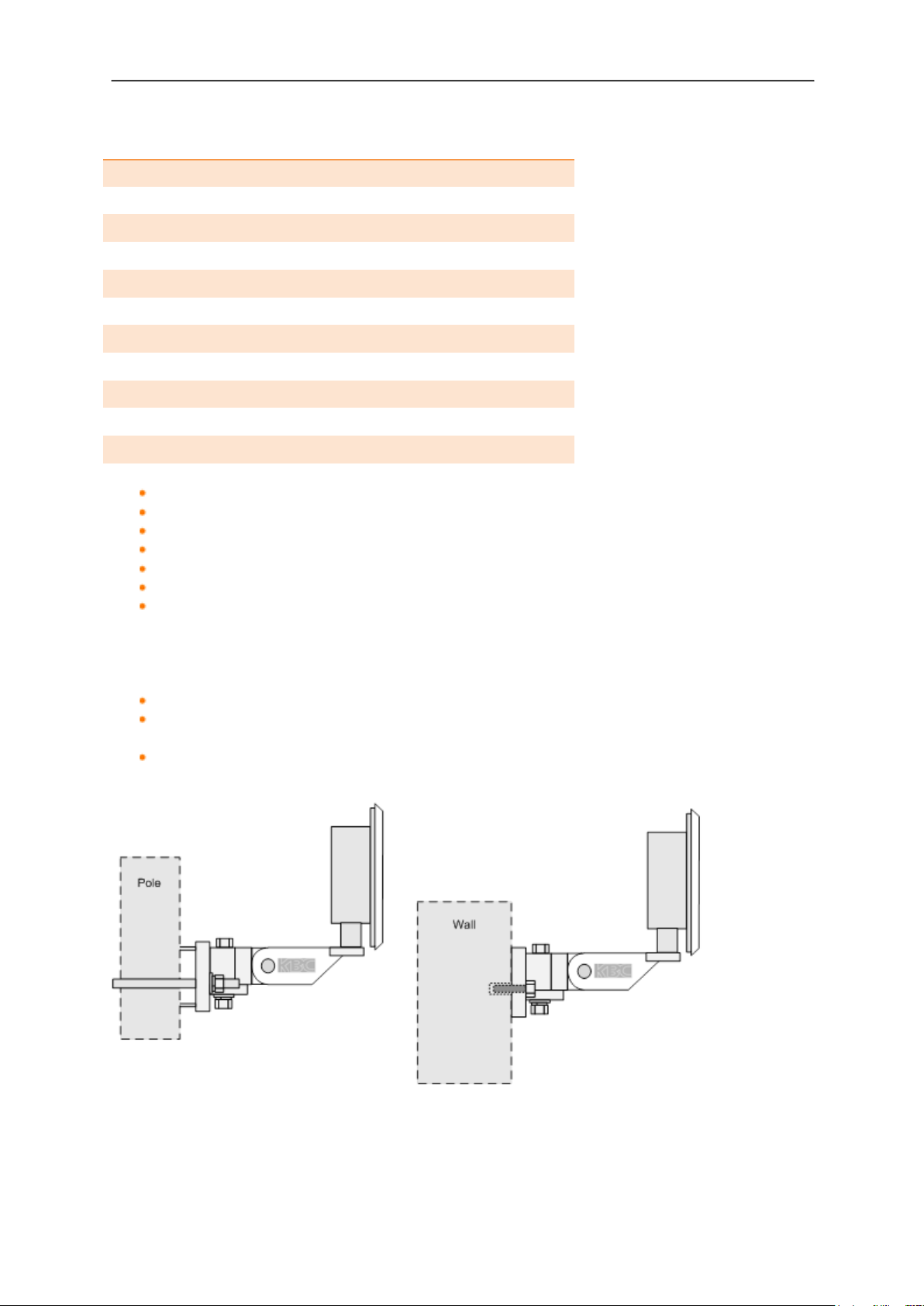
5. Mounting Instructions
WES2HT units are sold with all necessary mounting brackets and screws for installation
on 76mm/3” diameter pole or wall mount.
Note: This equipment must be installed in accordance with the instructions found in this
manual. The orientation must be as depicted below. Failure to comply with these
instructions will invalidate warranty.
5.1 Pole and wall-mount for WES2HT units
Manual-WES2HT-Rev1407-1
Copyright © KBC Networks 2013 Page 23 of 142
www.kbcnetworks.com
WES2HT User Manual
Qty Description
1 Bracket body
1 Pole clamp bracket
1 Connecting piece 1
1 Connecting piece 2
1 50mm, 1.98” long ¼” hex bolt
3 ¼” hex nuts
1 27mm, 1.06” long ¼” hex bolt
3 Flat washers 15mm, 0.59”
3 Locking washers 10mm, 0.39” long
1 U bolt
4 ¼-20 lock washers
Remove all packaging material
Remove 50mm bolt, flat washer, locking washer and hex nut.
Mount back plate to front WES2HT assembly plate.
Replace flat washer, locking washer and hex nut.
Remove ‘U’ shaped bolt.
Bolt the unit to the pole.
Up/Down Alignment offers one position when using the pre-fabricated channel
lock grooves on the swivel brackets. Directional antennas may require additional
up/down alignment angles than those allowed on the pre-fabricated grooves. To
achieve different angles, remove the 50mm Hex bolt. Insert the longer bolt and
add the star washer. Re-connect and tighten.
Position the WES2HT unit to face the WES2HT unit at the other end of the link.
Carry out the alignment process – see Section 10.4 for instructions and Section 7
for LED status information.
When in the best position, tighten.
Manual-WES2HT-Rev1407-1
Copyright © KBC Networks 2013 Page 24 of 142
www.kbcnetworks.com
WES2HT User Manual
2
4
5
6
1
1
1
3
4
5
6
6. Connections
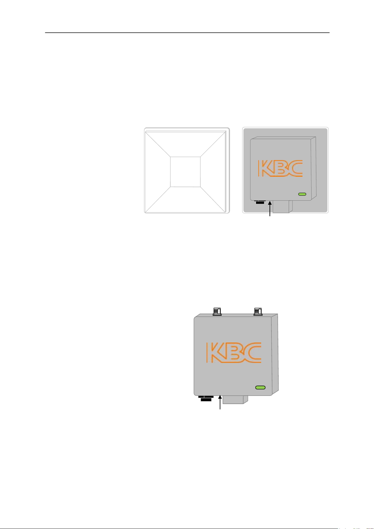
6.1 Physical Connections
6.1.1 Integrated Patch Antenna Chassis
1. Patch antenna cover
2. Serial number label
3. Internal RF module
enclosure
4. Status LEDs
5. LAN port (RJ45)
6. Mounting block
7. Reset to default button
Front view
7
Rear view
6.1.2 External Antenna Chassis
1. Antenna ports, attach screw down
omni-directional antennas (for directional
antennas, connect jumper LMR-200 cable)
2. Serial number label
3. Internal RF module enclosure
4. Status LEDs
5. LAN port (RJ-45)
6. Mounting block
7. Reset to default button
Rear view
Note: See Section 11.2.2.3 for details of how to perform a hard reset to default settings.
2
7
3
Manual-WES2HT-Rev1407-1
Copyright © KBC Networks 2013 Page 25 of 142
www.kbcnetworks.com
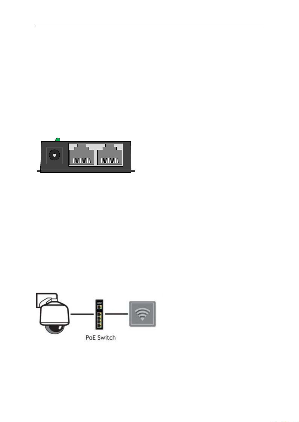
WES2HT User Manual
1. Power supply input
2. Power LED
3. LAN and power out to the WES2HT
4. LAN input from Ethernet device
5. Mounting tabs
1
2
3
4
5
WES2HT Client
6.2 Power Connections
WES2HT units support both PoE and non-PoE power configurations.
6.2.1 Power Injector Module for the non-PoE configuration
WES2HT units are supplied with a mid-span Power Injector Module (PIM) and a standard
24Vdc, 500mA Power Supply Unit, however, they can be bypassed when connecting
directly from a IEEE 802.3af PSE device (section 6.2.2 below).
Note: The Power Injector Modules (PIM) are not weatherproof units and must be
protected from moisture.
For extreme temperature conditions there is also a KBC Networks Industrial DIN Rail
power supply available, part number MDR-20-24. These units provide 24W at 24Vdc.
These units need to be purchased separately, for further details please contact KBC
Networks.
6.2.2 Alternative Power Option for the WES2HT
The WES2HT units are capable of being IEEE 802.3af Powered Devices (PD) ie. they can
also be powered from a Power Sourcing Equipment (PSE) such as an Ethernet switch
which provides power on the Ethernet cable. There are a number of different Ethernet
switches options with PoE available from KBC Networks, these can be purchased
separately. Please contact KBC Networks for further information.
Manual-WES2HT-Rev1407-1
Copyright © KBC Networks 2013 Page 26 of 142 www.kbcnetworks.com

WES2HT User Manual
7. LED Status
7.1 LED Description
1 Signal Strength Indicator – 40 RSSI
2 Signal Strength Indicator – 30 RSSI
3 Signal Strength Indicator – 20 RSSI
4 Signal Strength Indicator – 10 RSSI
5 Not used
6 Ethernet Link Activity
7 Power
7.1.1 LED Boot Up Process
Upon connection of an Ethernet cable from the PSE to the unit, the Power LED 7
will light.
After 1 second RSSI LEDs 1, 2 & 3 illuminate.
RSSI LEDs 1, 2 & 3 then go off.
After 5 seconds the Ethernet Link Activity LED 6, illuminates.
At the same time the Signal Strength Indicator, LED 1 flashes for approximately 2
seconds.
LEDs 1 & 6 then switch off.
LED 6 comes on again and flashes intermittently showing that a connection is
established.
After approximately 1 – 2 minutes RSSI LEDs 1, 2, 3 & 4 will light depending on
the level of signal strength.
Manual-WES2HT-Rev1407-1
Copyright © KBC Networks 2013 Page 27 of 142
www.kbcnetworks.com

WES2HT User Manual
8. Cable Assembly
8.1 Strain Relief Assembly
1. Thread the Cat 5 cable through the hole in the gland.
2. Pull the cable through and crimp on the RJ45 connector – see section 8.2
3. Connect the RJ45 connector into the WES2HT’s LAN port.
4. Tighten the clamping nut until the Ethernet cable is secured in the connector until it
is hand tight.
!Warning! DO NOT OVER-TIGHTEN. Over-torquing can damage the port and/or the
internal board inside. Also do not grab the black exterior housing with a wrench.
Turning that portion of the port will not detach the cable assembly or threading
piece, it will only damage the device.
Note: the RJ45 connector does move slightly within the LAN port on the WES2HT unit
this allows the RJ45 connector to be connected to the Ethernet port more easily.
8.2 Configuring the Cable.
Note: The total length of cable from the WES2HT to the Ethernet device cannot exceed
100m (325 feet); however, for a non-PoE WES2HT unit the PIM can be located anywhere
along the overall 100m of cable. KBC Networks recommends shielded Ethernet cables for
the cable connecting the PIM to the WES2HT unit. Any cable exposed to the elements
should also be outdoor rated.
1. Determine the length of cable that will be required and where the PIM will be
located.
2. Slide the weatherproof connector over the cable jacket before crimping the
connector. See Section 8.1 for the assembly instructions. If needed, see below for
color-code standards to configure the correct type of Ethernet cable.
Note: Ethernet standard straight-through cable configurations used must be configured
to one of the Ethernet standards (568-A or 568-B) in order for the WES2HT system to
operate efficiently. Any deviation from one of the two standard configurations can lead to
undesired activity.
Manual-WES2HT-Rev1407-1
Copyright © KBC Networks 2013 Page 28 of 142
www.kbcnetworks.com

WES2HT User Manual
Pin out for color codes 568-A and 568-B:
568-A 568-B
1- Green/White 1- Orange/White
2- Solid Green 2- Solid Orange
3- Orange/White 3- Green/White
4- Solid Blue 4- Solid Blue
5- Blue/White 5- Blue/White
6- Solid Orange 6- Solid Green
7- Brown/White 7- Brown/White
8- Solid Brown 8- Solid Brown
A cable configured with the 568-A color code on one end and the 568-B color code on
the other end is an Ethernet standard crossover cable.
8.3 Disconnecting the Cable from the External LAN
Port.
When the system must be removed from its mounted position for servicing and the
Ethernet cable must be removed from the RJ45 port, follow these steps:
1. Loosen the strain relief (see warning note above in section 8.1, step 4).
2. Using a small flathead screw driver (or something flat and long, or even the long
flat portion of a pen cap), depress the RJ45 tab that secures the connector into
the port. Do not attempt to remove the cable without depressing in the RJ45
connector tab or the port will get pulled loose from the housing.
3. At this point the cable can be removed from the RJ45 port.
Manual-WES2HT-Rev1407-1
Copyright © KBC Networks 2013 Page 29 of 142 www.kbcnetworks.com

WES2HT User Manual
9. Setting up a basic link
It is highly recommended that all equipment be bench tested before being installed on
site.
You will need:
4 x straight through Ethernet cables.
Note: It is recommended that for bench testing Host and Client units be placed face
downwards with a distance of 5 – 10m between them to avoid saturation.
The following sections deal with setting up basic links for the three different firmware
versions:
US & Canada
EMEA
Australian
Manual-WES2HT-Rev1407-1
Copyright © KBC Networks 2013 Page 30 of 142
www.kbcnetworks.com

WES2HT User Manual
9.1 Setting up a basic point-to-point link – United
States & Canada
9.1.1 Host configuration for point-to-point - United States & Canada
Step 1: Remove the WES2HT point-to-point Host, Power Supply Unit (PSU) and
Power Injector Modules (PIM) from the box.
Step 2a: Connect the first Ethernet straight through cable from the ‘IN’ on the PIM
to either a laptop or a PC LAN port.
Connect the second Ethernet straight through cable from ‘OUT’ on the
same PIM to the WES2HT Host LAN port.
Apply power to the PIM with the provided 24Vdc PSU and allow 60 seconds
for the unit to boot up.
WES2HT Host
Step 2b: The unit can also be powered via 802.3af PSE:
Connect an Ethernet cable from the PSE device (eg. Ethernet switch) to
the LAN port of the WES2HT unit.
Connect a second Ethernet cable from another port on the PSE to the
laptop or PC LAN port.
Apply power to the PSE device and allow 60 seconds for the unit to boot
up.
WES2HT Host
Step 3: Set the static IP address on the laptop to the 192.168.1.x subnet.
Step 4: Open a web browser to access the Host on its 192.168.1.200 IP address;
this is the default IP address for the Host unit.
Manual-WES2HT-Rev1407-1
Copyright © KBC Networks 2013 Page 31 of 142
www.kbcnetworks.com

WES2HT User Manual
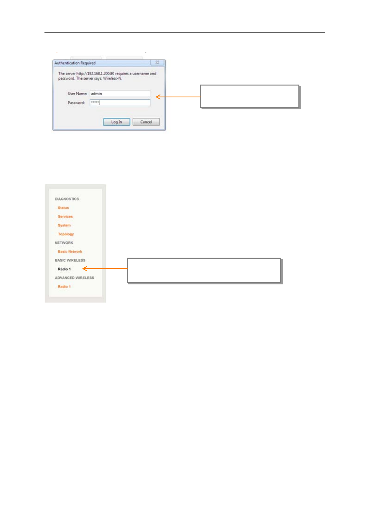
Step 5: Enter the following to access the GUI:
User Name: admin
Password: admin
Note: ensure that all other network interface connections including your laptop Wi-Fi are
disabled.
Step 6: Basic Wireless
Select: <Radio 1> under the ‘BASIC
WIRELESS’ option from the left hand
Step 7: Ensure that the Auto box is checked, the unit will chose the most suitable
channel. For systems with more than one point-to-point link on a site you
will need to manually set the channel frequency so that each point-to-point
link operates on a different frequency. See Section 11.2.6.1 Manual setting
for details for manually setting the channel frequency.
Ensure this box is
checked
Manual-WES2HT-Rev1407-1
Copyright © KBC Networks 2013 Page 32 of 142
www.kbcnetworks.com

WES2HT User Manual
Step 8: Enter the MAC address of the Client unit that the Host will connect to in
the ‘Remote Client-Lock to MAC’. This can be found on the ‘Status’ page of
the Client unit or the rear label on the outside of the unit. The MAC
address must be entered in the following format: xx:xx:xx:xx:xx:xx.
Enter the Client MAC
address here
Step 9: Apply Settings
Step 10: Save the changes.
Select: <Apply Settings>
Select: <Save>
Manual-WES2HT-Rev1407-1
Copyright © KBC Networks 2013 Page 33 of 142
www.kbcnetworks.com

WES2HT User Manual
9.1.2 Client configuration for point-to-point - United States & Canada
Step 1: Remove the WES2HT Client, Power Supply Unit (PSU) and Power Injector
Modules (PIM) (for non-PoE units only) from the box.
Step 2a: Connect the first Ethernet straight through cable from the ‘IN’ on the PIM
to either a laptop or a PC LAN port.
Connect the second Ethernet straight through cable from ‘OUT’ on the
same PIM to the WES2HT Host LAN port.
Apply power to the PIM with the provided 24Vdc PSU and allow 60 seconds
for the unit to boot up.
WES2HT Client
Step 2b: The unit can also be powered via 802.3af PSE:
Connect an Ethernet cable from the PSE device (eg. Ethernet switch) to
the LAN port of the WES2HT unit.
Connect a second Ethernet cable from another port on the PSE to the
laptop or PC LAN port.
Apply power to the PSE device and allow 60 seconds for the unit to boot
up.
WES2HT Client
Step 3: Set the static IP address on the laptop to the 192.168.1.x subnet.
Step 4: Open a web browser to access the Client on its 192.168.1.201 IP address;
this is the default IP address for the Client unit.
Manual-WES2HT-Rev1407-1
Copyright © KBC Networks 2013 Page 34 of 142
www.kbcnetworks.com
WES2HT User Manual
Step 5: Enter the following to access the GUI:
User Name: admin
Password: admin
Note: ensure that all other network interface connections including your laptop Wi-Fi are
disabled.
Step 6: Basic Wireless
Select: <Radio 1> under the ‘BASIC
WIRELESS’ option from the left hand menu
Manual-WES2HT-Rev1407-1
Copyright © KBC Networks 2013 Page 35 of 142
www.kbcnetworks.com

WES2HT User Manual
Step 7: Check the Remote AP-Lock to MAC box
Check this box
Step 8: Ensure that the Channel Spectrum Width is on 20/40M & ensure that the
Remote AP-ESSID is set to the same as the Host unit.
Manual-WES2HT-Rev1407-1
Copyright © KBC Networks 2013 Page 36 of 142
Ensure these are the same as
the Host unit you want to
connect to
www.kbcnetworks.com

WES2HT User Manual
Step 9: Select Site Survey to find the WES2HT Host you want to connect to.
Select: <Site Survey>
Step 10: The Site Survey will search for the KBC WES2HT Host that you want to
connect to. Click on the actual MAC address of the Host unit you want to
connect to.
Select: the MAC address eg.
3c:0f:c1:00:25:3a
Step 11: The Host address should now appear in the Remote AP-Lock to MAC
address window.
Host MAC address selected that the
Client is now locked to
Note: it is recommended that you write down all the MAC addresses and SSIDs used in
the application for future reference.
Manual-WES2HT-Rev1407-1
Copyright © KBC Networks 2013 Page 37 of 142
www.kbcnetworks.com

WES2HT User Manual
Step 12: The WES2HT units will take approximately 2 minutes to connect to each
other. Once a connection has been made the RSSI LEDs on the back of the
unit will light to show the strength of the connection. See Section 7.
Step 13: You will now be able to connect to the Host unit via the Client across the
link that has been set up. To do this open another tab on your web
browser and access the Host on its 192.169.1.200 default address.
Unless a more advanced set up is desired, the antennas are configured for installation at
this point. For advanced configuration see Section 11.
Manual-WES2HT-Rev1407-1
Copyright © KBC Networks 2013 Page 38 of 142 www.kbcnetworks.com

WES2HT User Manual
9.2 Setting up a basic point-to-point link – EMEA
9.2.1 Host configuration for point-to-point - EMEA
Step 1: Remove the WES2HT PoE point-to-point Host, Power Supply Unit (PSU)
and Power Injector Modules (PIM) from the box.
Step 2a: Connect the first Ethernet straight through cable from the ‘IN’ on the PIM
to either a laptop or a PC LAN port.
Connect the second Ethernet straight through cable from ‘OUT’ on the
same PIM to the WES2HT Host LAN port.
Apply power to the PIM with the provided 24Vdc PSU and allow 60 seconds
for the unit to boot up.
Step 2b: The unit can also be powered via 802.3af PSE:
Connect an Ethernet cable from the PSE device (eg. Ethernet switch) to
the LAN port of the WES2HT unit.
Connect a second Ethernet cable from another port on the PSE to the
laptop or PC LAN port.
Apply power to the PSE device and allow 60 seconds for the unit to boot
up.
Step 3: Set the static IP address on the laptop to the 192.168.1.x subnet.
Step 4: Open a web browser to access the Host on its 192.168.1.200 IP address;
this is the default IP address for the Host unit.
Manual-WES2HT-Rev1407-1
Copyright © KBC Networks 2013 Page 39 of 142
www.kbcnetworks.com

WES2HT User Manual
Step 5: Enter the following to access the GUI:
User Name: admin
Password: admin
Note: ensure that all other network interface connections including your laptop Wi-Fi are
disabled.
Step 6: Basic Wireless
Select: <Radio 1> under the ‘BASIC
WIRELESS’ option from the left hand menu
Manual-WES2HT-Rev1407-1
Copyright © KBC Networks 2013 Page 40 of 142
www.kbcnetworks.com

WES2HT User Manual
Step 7: Selecting the correct country
Note: It is the user’s responsibility to ensure that the correct country is selected. KBC
Networks accepts no liability for incorrectly configured equipment.
Select: the country where the unit will
be operating
Step 8: Apply the country setting.
Select: <Apply Settings>
Manual-WES2HT-Rev1407-1
Copyright © KBC Networks 2013 Page 41 of 142
www.kbcnetworks.com

WES2HT User Manual
Select: <Save>
Step 9: Save
Step 10: Ensure that the Auto box is checked, the unit will chose the most suitable
channel. For systems with more than one point-to-point link on a site you
will need to manually set the channel frequency so that each point-to-point
link operates on a different frequency. See Section 11.2.6.1 Manual setting
for details for manually setting the channel frequency.
Manual-WES2HT-Rev1407-1
Copyright © KBC Networks 2013 Page 42 of 142
www.kbcnetworks.com

WES2HT User Manual
Ensure this box is
checked
Manual-WES2HT-Rev1407-1
Copyright © KBC Networks 2013 Page 43 of 142
www.kbcnetworks.com

WES2HT User Manual
Step 11: Enter the MAC address of the Client unit that the Host will connect to in
the ‘Remote Client-Lock to MAC’. This can be found on the ‘Status’ page of
the Client unit or on the rear label on the outside of the unit. The MAC
address must be entered in the following format: xx:xx:xx:xx:xx:xx.
Enter the Client MAC
address here
Step 12: Apply Settings
Select: <Apply Settings>
Manual-WES2HT-Rev1407-1
Copyright © KBC Networks 2013 Page 44 of 142
www.kbcnetworks.com

WES2HT User Manual
Select: <Save>
Step 13: Save the changes.
Manual-WES2HT-Rev1407-1
Copyright © KBC Networks 2013 Page 45 of 142
www.kbcnetworks.com

WES2HT User Manual
9.2.2 Client configuration for point-to-point - EMEA
Step 1: Remove the WES2HT Client, Power Supply Unit (PSU) and Power Injector
Modules (PIM) (for non-PoE units only) from the box.
Step 2a: Connect the first Ethernet straight through cable from the ‘IN’ on the PIM
to either a laptop or a PC LAN port.
Connect the second Ethernet straight through cable from ‘OUT’ on the
same PIM to the WES2HT Host LAN port.
Apply power to the PIM with the provided 24Vdc PSU and allow 60 seconds
for the unit to boot up.
Step 2b: The unit can also be powered via 802.3af PSE:
Connect an Ethernet cable from the PSE device (eg. Ethernet switch) to
the LAN port of the WES2HT unit.
Connect a second Ethernet cable from another port on the PSE to the
laptop or PC LAN port.
Apply power to the PSE device and allow 60 seconds for the unit to boot
up.
Step 3: Set the static IP address on the laptop to the 192.168.1.x subnet.
Step 4: Open a web browser to access the Client on its 192.168.1.201 IP address;
this is the default IP address for the Client unit.
Manual-WES2HT-Rev1407-1
Copyright © KBC Networks 2013 Page 46 of 142
www.kbcnetworks.com

WES2HT User Manual
Step 5: Enter the following to access the GUI:
User Name: admin
Password: admin
Note: ensure that all other network interface connections including your laptop Wi-Fi are
disabled.
Step 6: Basic Wireless
Select: <Radio 1> under the ‘BASIC
WIRELESS’ option from the left hand menu
Manual-WES2HT-Rev1407-1
Copyright © KBC Networks 2013 Page 47 of 142
www.kbcnetworks.com

WES2HT User Manual
Step 7: Select the correct country.
Select: the country where the unit will
be operating
Note: It is the user’s responsibility to ensure that the correct Country is selected. KBC
Networks accepts no liability for incorrectly configured equipment.
Manual-WES2HT-Rev1407-1
Copyright © KBC Networks 2013 Page 48 of 142
www.kbcnetworks.com

WES2HT User Manual
Step 8: Apply the country setting.
Select: <Apply Settings>
Select: <Save>
Step 9: Save
Manual-WES2HT-Rev1407-1
Copyright © KBC Networks 2013 Page 49 of 142
www.kbcnetworks.com

WES2HT User Manual
Step 10: Check the Remote AP-Lock to MAC box
Check this box
Manual-WES2HT-Rev1407-1
Copyright © KBC Networks 2013 Page 50 of 142
www.kbcnetworks.com

WES2HT User Manual
Step 11: Ensure that the Channel Spectrum Width is on 20/40M & ensure that the
remote AP-ESSID and Country Code are set to the same as the Host unit.
Ensure this is the same as the
Host unit you want to connect
to.
Ensure this is the same as the
Host unit you want to connect
to.
Ensure this is on 20/40M
Step 12: Select Site Survey to find the WES2HT Host you want to connect to.
Select: <Site Survey>
Step 13: The Site Survey will search for the KBC WES2HT Host that you want to
connect to. Click on the actual MAC address of the Host unit you want to
connect to.
Select: the MAC address eg.
3c:0f:c1:00:25:3a
Manual-WES2HT-Rev1407-1
Copyright © KBC Networks 2013 Page 51 of 142
www.kbcnetworks.com

WES2HT User Manual
Step 14: The Host address should now appear in the Remote AP-Lock to MAC
address window.
Host MAC address selected that the
Client is now locked to
Note: it is recommended that you write down all the MAC addresses and SSIDs used in
the application for future reference.
Step 15: The WES2HT units will take approximately 2 minutes to connect to each
other. Once a connection has been made the RSSI LEDs on the back of the
unit will light to show the strength of the connection. See Section 7.
Step 16: You will now be able to connect to the Host unit via the Client across the
link that has been set up. To do this open another tab on your web
browser and access the Host on its 192.169.1.200 default address.
Unless a more advanced set up is desired, the antennas are configured for installation at
this point. For advanced configuration see Section 11.
Manual-WES2HT-Rev1407-1
Copyright © KBC Networks 2013 Page 52 of 142
www.kbcnetworks.com
WES2HT User Manual
9.3 Setting up a basic point-to-point link – Australia
9.3.1 Host configuration for point-to-point - Australia
Step 1: Remove the WES2HT point-to-point Host, Power Supply Unit (PSU) and
Power Injector Modules (PIM) (for non-PoE units only) from the box.
Step 2a: Connect the first Ethernet straight through cable from the ‘IN’ on the PIM
to either a laptop or a PC LAN port.
Connect the second Ethernet straight through cable from ‘OUT’ on the
same PIM to the WES2HT Host LAN port.
Apply power to the PIM with the provided 24Vdc PSU and allow 60 seconds
for the unit to boot up.
Step 2b: The unit can also be powered via 802.3af PSE:
Connect an Ethernet cable from the PSE device (eg. Ethernet switch) to
the LAN port of the WES2HT unit.
Connect a second Ethernet cable from another port on the PSE to the
laptop or PC LAN port.
Apply power to the PSE device and allow 60 seconds for the unit to boot
up.
Step 3: Set the static IP address on the laptop to the 192.168.1.x subnet.
Step 4: Open a web browser to access the Host on its 192.168.1.200 IP address;
this is the default IP address for the Host unit.
Step 5: Enter the following to access the GUI:
Manual-WES2HT-Rev1407-1
Copyright © KBC Networks 2013 Page 53 of 142
www.kbcnetworks.com

WES2HT User Manual
User Name: admin
Password: admin
Note: ensure that all other network interface connections including your laptop Wi-Fi are
disabled.
Step 6: Basic Wireless
Select: <BASIC WIRELESS> under the
‘NETWORK’ option from the left hand menu
Step 7: Ensure that the Auto box is checked, the unit will chose the most suitable
channel. For systems with more than one point-to-point link on a site you
will need to manually set the channel frequency so that each point-to-point
link operates on a different frequency. See Section 11.2.6.1 Manual setting
for details for manually setting the channel frequency.
Ensure this box is
checked
Manual-WES2HT-Rev1407-1
Copyright © KBC Networks 2013 Page 54 of 142
www.kbcnetworks.com

WES2HT User Manual
Step 8: Enter the MAC address of the Client unit that the Host will connect to in
the ‘Remote Client-Lock to MAC’. This can be found on the Status page of
the Client unit or the rear label on the outside of the unit. The MAC
address must be in the format: xx:xx:xx:xx:xx:xx.
Enter the Client MAC
address here.
Step 9: Apply Settings
Step 10: Save the changes.
Select: <Apply Settings>
Select: <Save>
Manual-WES2HT-Rev1407-1
Copyright © KBC Networks 2013 Page 55 of 142
www.kbcnetworks.com
WES2HT User Manual
9.3.2 Client configuration for point-to-point - Australia
Step 1: Remove the WES2HT Client, Power Supply Unit (PSU) and Power Injector
Modules (PIM) from the box.
Step 2a: Connect the first Ethernet straight through cable from the ‘IN’ on the PIM
to either a laptop or a PC LAN port.
Connect the second Ethernet straight through cable from ‘OUT’ on the
same PIM to the WES2HT Host LAN port.
Apply power to the PIM with the provided 24Vdc PSU and allow 60 seconds
for the unit to boot up.
Step 2b: The unit can also be powered via 802.3af PSE:
Connect an Ethernet cable from the PSE device (eg. Ethernet switch) to
the LAN port of the WES2HT unit.
Connect a second Ethernet cable from another port on the PSE to the
laptop or PC LAN port.
Apply power to the PSE device and allow 60 seconds for the unit to boot
up.
Step 3: Set the static IP address on the laptop to the 192.168.1.x subnet.
Step 4: Open a web browser to access the Client on its 192.168.1.201 IP address;
this is the default IP address for the Client unit.
Step 5: Enter the following to access the GUI:
Manual-WES2HT-Rev1407-1
Copyright © KBC Networks 2013 Page 56 of 142
www.kbcnetworks.com

WES2HT User Manual
User Name: admin
Password: admin
Note: ensure that all other network interface connections including your laptop Wi-Fi are
disabled.
Step 6: Basic Wireless
Select: <BASIC WIRELESS> under the
‘NETWORK’ option from the left hand menu
Manual-WES2HT-Rev1407-1
Copyright © KBC Networks 2013 Page 57 of 142
www.kbcnetworks.com

WES2HT User Manual
Step 7: Check the Remote AP-Lock to MAC box
Check this box
Step 8: Ensure that the Channel Spectrum Width is on 20/40M & ensure that the
Remote AP-ESSID are set to the same as the Host unit.
Manual-WES2HT-Rev1407-1
Copyright © KBC Networks 2013 Page 58 of 142
Ensure these are the same as
the Host unit you want to
connect to
www.kbcnetworks.com

WES2HT User Manual
Step 9: Select Site Survey to find the WES2HT Host you want to connect to.
Select: <Site Survey>
Step 10: The Site Survey will search for the KBC WES2HT Host that you want to
connect to. Click on the actual MAC address of the Host unit you want to
connect to.
Select: the MAC address eg.
3c:0f:c1:00:25:3a
Step 11: The Host address should now appear in the Remote AP-Lock to MAC
address window.
Host MAC address selected that the
Client is now locked to
Note: it is recommended that you write down all the MAC addresses and SSIDs used in
the application for future reference.
Manual-WES2HT-Rev1407-1
Copyright © KBC Networks 2013 Page 59 of 142
www.kbcnetworks.com

WES2HT User Manual
Step 12: The WES2HT units will take approximately 2 minutes to connect to each
other. Once a connection has been made the RSSI LEDs on the back of the
unit will light to show the strength of the connection. See Section 7.
Step 13: You will now be able to connect to the Host unit via the Client across the
link that has been set up. To do this open another tab on your web
browser and access the Host on its 192.169.1.200 default address.
Unless a more advanced set up is desired, the antennas are configured for installation at
this point. For advanced configuration see Section 11.
Manual-WES2HT-Rev1407-1
Copyright © KBC Networks 2013 Page 60 of 142 www.kbcnetworks.com

WES2HT User Manual
9.4 Setting up a basic point-to-multipoint link United States & Canada
9.4.1 Host configuration for point-to-multipoint - United States &
Canada
Step 1: Remove the WES2HT point-to-multipoint Host, Power Supply Unit (PSU)
and Power Injector Modules (PIM) (for non-PoE units only) from the box.
Step 2a: Connect the first Ethernet straight through cable from the ‘IN’ on the PIM
to either a laptop or a PC LAN port.
Connect the second Ethernet straight through cable from ‘OUT’ on the
same PIM to the WES2HT Host LAN port.
Apply power to the PIM with the provided 24Vdc PSU and allow 60 seconds
for the unit to boot up.
Step 2b: The unit can also be powered via 802.3af PSE:
Connect an Ethernet cable from the PSE device (eg. Ethernet switch) to
the LAN port of the WES2HT unit.
Connect a second Ethernet cable from another port on the PSE to the
laptop or PC LAN port.
Apply power to the PSE device and allow 60 seconds for the unit to boot
up.
Manual-WES2HT-Rev1407-1
Copyright © KBC Networks 2013 Page 61 of 142
www.kbcnetworks.com
Step 3: Set the
static IP address on

WES2HT User Manual
the laptop to the 192.168.1.x subnet.
Step 4: Open a web browser to access the Host on its 192.168.1.200 IP address;
this is the default IP address for the Host unit.
Step 5: Enter the following to access the GUI:
User Name: admin
Password: admin
Note: ensure that all other network interface connections including your laptop Wi-Fi are
disabled.
Step 6: Basic Wireless
Select: <Radio 1> under the ‘BASIC
WIRELESS’ option from the left hand menu
Manual-WES2HT-Rev1407-1
Copyright © KBC Networks 2013 Page 62 of 142
www.kbcnetworks.com

WES2HT User Manual
checked
Step 7: Ensure that the Auto box is checked, the unit will chose the most suitable
channel. For systems with more than one point-to-multipoint link on a site
you will need to manually set the channel frequency for each group of Host
and Clients so that each group operates on a different frequency. See
Section 11.2.6.1 Manual setting for details of how to manually set the
channel frequency.
Ensure this box is
Manual-WES2HT-Rev1407-1
Copyright © KBC Networks 2013 Page 63 of 142
www.kbcnetworks.com

WES2HT User Manual
WESII PoE
Client
PoE switch
9.4.2 Client configuration for point-to-multipoint - United States &
Canada
Setting up each Client
Step 1: Remove the WES2HT Clients, Power Supply Units (PSUs) and Power
Injector Modules (PIMs) (for non-PoE units only) from the box.
Step 2a: Connect the first Ethernet straight through cable from the ‘IN’ on the PIM
to either a laptop or a PC LAN port.
Connect the second Ethernet straight through cable from ‘OUT’ on the
same PIM to the WES2HT Host LAN port.
Apply power to the PIM with the provided 24Vdc PSU and allow 60 seconds
for the unit to boot up.
Step 2b: The unit can also be powered via 802.3af PSE:
Connect an Ethernet cable from the PSE device (eg. Ethernet switch) to
the LAN port of the WES2HT unit.
Connect a second Ethernet cable from another port on the PSE to the
laptop or PC LAN port.
Apply power to the PSE device and allow 60 seconds for the unit to boot
up.
Step 3: Set the static IP address on the laptop to the 192.168.1.x subnet.
Manual-WES2HT-Rev1407-1
Copyright © KBC Networks 2013 Page 64 of 142
www.kbcnetworks.com

WES2HT User Manual
For each Client to be linked to the point-to-multipoint Host:
Step 4: Open a web browser to access each of the Clients on its 192.168.1.201 IP
address; this is the default IP address for the Client unit.
Step 5: Enter the following to access the GUI:
User Name: admin
Password: admin
Note: ensure that all other network interface connections including your laptop Wi-Fi are
disabled.
Step 6: Basic Wireless
Select: <Radio 1> under the ‘BASIC
WIRELESS’ option from the left hand menu
Manual-WES2HT-Rev1407-1
Copyright © KBC Networks 2013 Page 65 of 142
www.kbcnetworks.com

WES2HT User Manual
Step 7: For each Client in the point-to-multipoint group you will have to assign an
individual IP address. In the NETWORK : Basic Network menu the default
IP address will be 192.168.1.201. Type in a new IP address on the
192.168.1.xx subnet eg. 192.168.1.8. For a site example see Section 10.
Client default IP address
NETWORK: Basic Network
Type in a new IP address on
the 192.168.1.xx subnet
Manual-WES2HT-Rev1407-1
Copyright © KBC Networks 2013 Page 66 of 142
www.kbcnetworks.com

WES2HT User Manual
Save
Step 8: Apply Settings and Save
Apply Settings
Manual-WES2HT-Rev1407-1
Copyright © KBC Networks 2013 Page 67 of 142
www.kbcnetworks.com

WES2HT User Manual
Step 9: Ensure that the Channel Spectrum Width is on 20/40M & ensure that the
Remote AP-ESSID is set to the same as the Host unit for each of the Client
units in the group. For a system with multiple, point-to-multipoint systems
you will need to assign separate SSID for every group of Host plus Client
units.
Ensure this is the same as the
Host unit you want to connect
to.
Ensure this is on 20/40M
Step 10: Select Site Survey to find the WES2HT Host you want to connect to.
Select: <Site Survey>
Step 11: The Site Survey will search for the KBC WES2HT Host that you want to
connect to. Click on the actual MAC address of the Host unit you want to
connect to.
Select: the MAC address eg.
Manual-WES2HT-Rev1407-1
Copyright © KBC Networks 2013 Page 68 of 142
3c:0f:c1:00:25:3a
www.kbcnetworks.com

WES2HT User Manual
Step 12: The Host IP address should now appear in the Remote AP-Lock to MAC
address window. The Client unit will pick up the Host unit’s frequency
automatically. You now have a connected link.
Host MAC address selected that the
Client is now paired with
Note: it is recommended that you write down all the MAC addresses and SSIDs used in
the application for future reference.
Step 13: The WES2HT units will take approximately 2 minutes to connect to each
other. Once a connection has been made the RSSI LEDs on the back of the
units will light to show the strength of the connection. See Section 7.
Step 14: Repeat the process for every Client that needs to be connected to the
Host.
Step 15: You will now be able to connect to the Host unit via the Client across the
link that has been set up. To do this open another tab on your web
browser and access the Host on its 192.169.1.200 default address.
Unless a more advanced set up is desired, the antennas are configured for installation at
this point. For advanced configuration see Section 11.
Manual-WES2HT-Rev1407-1
Copyright © KBC Networks 2013 Page 69 of 142
www.kbcnetworks.com

WES2HT User Manual
9.5 Setting up a basic point-to-multipoint link – EMEA
9.5.1 Host configuration for point-to-multipoint - EMEA
Step 1: Remove the WES2HT point-to-multipoint Host, Power Supply Unit (PSU)
and Power Injector Modules (PIM) (for non-PoE units only) from the box.
Step 2a: Connect the first Ethernet straight through cable from the ‘IN’ on the PIM
to either a laptop or a PC LAN port.
Connect the second Ethernet straight through cable from ‘OUT’ on the
same PIM to the WES2HT Host LAN port.
Apply power to the PIM with the provided 24Vdc PSU and allow 60 seconds
for the unit to boot up.
Step 2b: The unit can also be powered via 802.3af PSE:
Connect an Ethernet cable from the PSE device (eg. Ethernet switch) to
the LAN port of the WES2HT unit.
Connect a second Ethernet cable from another port on the PSE to the
laptop or PC LAN port.
Apply power to the PSE device and allow 60 seconds for the unit to boot
up.
Step 3: Set the static IP address on the laptop to the 192.168.1.x subnet.
Manual-WES2HT-Rev1407-1
Copyright © KBC Networks 2013 Page 70 of 142
www.kbcnetworks.com

WES2HT User Manual
Step 4: Open a web browser to access the Host on its 192.168.1.200 IP address;
this is the default IP address for the Host unit.
Step 5: Enter the following to access the GUI:
User Name: admin
Password: admin
Note: ensure that all other network interface connections including your laptop Wi-Fi are
disabled.
Step 6: Basic Wireless
Select: <Radio 1> under the ‘BASIC
WIRELESS’ option from the left hand menu
Manual-WES2HT-Rev1407-1
Copyright © KBC Networks 2013 Page 71 of 142
www.kbcnetworks.com
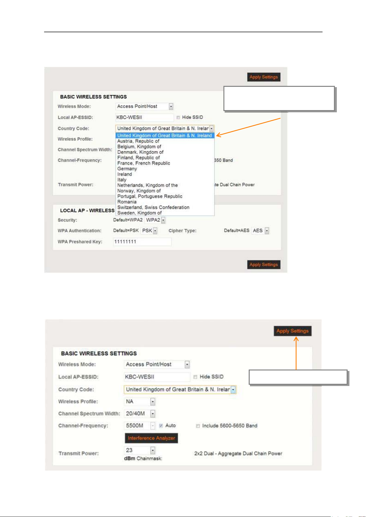
WES2HT User Manual
Step 7: Select the correct country.
Select: the country where the
unit will be operating
Note: It is the user’s responsibility to ensure that the correct country is selected. KBC
Networks accepts no liability for incorrectly configured equipment.
Step 8: Apply the country setting.
Select: <Apply Settings>
Manual-WES2HT-Rev1407-1
Copyright © KBC Networks 2013 Page 72 of 142
www.kbcnetworks.com

WES2HT User Manual
Step 9: Save.
Select: <Save>
Step 10: Ensure that the Auto box is checked, the unit will chose the most suitable
channel. For systems with more than one point-to-multipoint link on a site
you will need to manually set the channel frequency for each group of Host
and Clients so that each group operates on a different frequency. See
Section 11.2.6.1 Manual setting for details of how to manually set the
channel frequency.
Ensure this box is
checked
Manual-WES2HT-Rev1407-1
Copyright © KBC Networks 2013 Page 73 of 142
www.kbcnetworks.com

WES2HT User Manual
9.5.2 Client configuration for point-to-multipoint - EMEA
Step 1: Remove the WES2HT Clients, Power Supply Units (PSUs) and Power
Injector Modules (PIMs) (for non-PoE units only) from the box.
Step 2a: Connect the first Ethernet straight through cable from the ‘IN’ on the PIM
to either a laptop or a PC LAN port.
Connect the second Ethernet straight through cable from ‘OUT’ on the
same PIM to the WES2HT Host LAN port.
Apply power to the PIM with the provided 24Vdc PSU and allow 60 seconds
for the unit to boot up.
Step 2b: The unit can also be powered via 802.3af PSE:
Connect an Ethernet cable from the PSE device (eg. Ethernet switch) to
the LAN port of the WES2HT unit.
Connect a second Ethernet cable from another port on the PSE to the
laptop or PC LAN port.
Apply power to the PSE device and allow 60 seconds for the unit to boot
up.
Step 3: Set the static IP address on the laptop to the 192.168.1.x subnet.
Manual-WES2HT-Rev1407-1
Copyright © KBC Networks 2013 Page 74 of 142
www.kbcnetworks.com

WES2HT User Manual
For each Client to be linked to the point-to-multipoint Host:
Step 4: Open a web browser to access each of the Clients on its 192.168.1.201 IP
address; this is the default IP address for the Client unit.
Step 5: Enter the following to access the GUI:
User Name: admin
Password: admin
Note: ensure that all other network interface connections including your laptop Wi-Fi are
disabled.
Step 6: Basic Wireless
Select: <Radio 1> under the ‘BASIC
WIRELESS’ option from the left hand menu
Manual-WES2HT-Rev1407-1
Copyright © KBC Networks 2013 Page 75 of 142
www.kbcnetworks.com

WES2HT User Manual
Step 7: Select the correct Country Code.
Select: the country where the unit will
be operating
Note: It is the user’s responsibility to ensure that the correct Country is selected. KBC
Networks accepts no liability for incorrectly configured equipment. A Country Code
setting is not required for units purchased in the US.
Manual-WES2HT-Rev1407-1
Copyright © KBC Networks 2013 Page 76 of 142
www.kbcnetworks.com

WES2HT User Manual
Step 8: Apply the Country Code setting.
Select: <Apply Settings>
Step 9: Save the settings.
Select: <Save>
Manual-WES2HT-Rev1407-1
Copyright © KBC Networks 2013 Page 77 of 142
www.kbcnetworks.com

WES2HT User Manual
Step 10: For each Client in the point-to-multipoint group you will have to assign an
individual IP address. In the NETWORK : Basic Network menu the default
IP address will be 192.168.1.201. Type in a new IP address on the
192.168.1.xx subnet eg. 192.168.1.8. For a site example see Section 10.
Client default IP
address
NETWORK: Basic Network
Type in a new IP address on
the 192.168.1.xx subnet
Manual-WES2HT-Rev1407-1
Copyright © KBC Networks 2013 Page 78 of 142
www.kbcnetworks.com

WES2HT User Manual
Step 11: Apply Settings and Save
Select: <Save>
Apply Settings
Manual-WES2HT-Rev1407-1
Copyright © KBC Networks 2013 Page 79 of 142
www.kbcnetworks.com

WES2HT User Manual
Step 12: Ensure that the Channel Spectrum Width is on 20/40M & ensure that the
Remote AP-ESSID and Country Code are set to the same as the Host unit
for each of the Client units in the group. For a system with multiple, pointto-multipoint systems you will need to assign separate SSID for every
group of Host plus Client units.
Ensure this is the same as the Host
unit you want to connect to.
Ensure this is the same as the
Host unit you want to connect
to
Ensure this is on 20/40M
Manual-WES2HT-Rev1407-1
Copyright © KBC Networks 2013 Page 80 of 142
www.kbcnetworks.com

WES2HT User Manual
Step 13: Select Site Survey to find the WES2HT Host you want to connect to.
Select: <Site Survey>
Step 14: The Site Survey will search for the KBC WES2HT Host that you want to
connect to. Click on the actual MAC address of the Host unit you want to
connect to.
Select: the MAC address eg.
3c:0f:c1:00:12:83
Manual-WES2HT-Rev1407-1
Copyright © KBC Networks 2013 Page 81 of 142
www.kbcnetworks.com

WES2HT User Manual
Step 15: The Host IP address should now appear in the Remote AP-Lock to MAC
address window. The Client unit will pick up the Host unit’s frequency
automatically. You now have a connected link.
Host MAC address selected that the
Client is now paired with
Note: it is recommended that you write down all the MAC addresses and SSIDs used in
the application for future reference.
Step 16: The WES2HT units will take approximately 2 minutes to connect to each
other. Once a connection has been made the RSSI LEDs on the back of the
units will light to show the strength of the connection. See Section 7.
Step 17: Repeat the process for every Client that needs to be connected to the
Host.
Step 18: You will now be able to connect to the Host unit via the Client across the
link that has been set up. To do this open another tab on your web
browser and access the Host on its 192.169.1.200 default address.
Unless a more advanced set up is desired, the antennas are configured for installation at
this point. For advanced configuration see Section 11.
Manual-WES2HT-Rev1407-1
Copyright © KBC Networks 2013 Page 82 of 142
www.kbcnetworks.com

WES2HT User Manual
9.6 Setting up a basic point-to-multipoint link –
Australia
9.6.1 Host configuration for point-to-multipoint - Australia
Step 1: Remove the WES2HT point-to-multipoint Host, Power Supply Unit (PSU)
and Power Injector Modules (PIM) (for non-PoE units only) from the box.
Step 2a: Connect the first Ethernet straight through cable from the ‘IN’ on the PIM
to either a laptop or a PC LAN port.
Connect the second Ethernet straight through cable from ‘OUT’ on the
same PIM to the WES2HT Host LAN port.
Apply power to the PIM with the provided 24Vdc PSU and allow 60 seconds
for the unit to boot up.
Step 2b: The unit can also be powered via 802.3af PSE:
Connect an Ethernet cable from the PSE device (eg. Ethernet switch) to
the LAN port of the WES2HT unit.
Connect a second Ethernet cable from another port on the PSE to the
laptop or PC LAN port.
Apply power to the PSE device and allow 60 seconds for the unit to boot
up.
Manual-WES2HT-Rev1407-1
Copyright © KBC Networks 2013 Page 83 of 142
www.kbcnetworks.com

WES2HT User Manual
Step 3: Set the static IP address on the laptop to the 192.168.1.x subnet.
Step 4: Open a web browser to access the Host on its 192.168.1.200 IP address;
this is the default IP address for the Host unit.
Step 5: Enter the following to access the GUI:
User Name: admin
Password: admin
Note: ensure that all other network interface connections including your laptop Wi-Fi are
disabled.
Step 6: Basic Wireless
Select: <BASIC WIRELESS> under the
‘NETWORK’ option from the left hand menu
Manual-WES2HT-Rev1407-1
Copyright © KBC Networks 2013 Page 84 of 142
www.kbcnetworks.com

WES2HT User Manual
Step 7: Ensure that the Auto box is checked, the unit will chose the most suitable
channel. For systems with more than one point-to-multipoint link on a site
you will need to manually set the channel frequency for each group of Host
and Clients so that each group operates on a different frequency. See
Section 11.2.6.1 Manual setting for details of how to manually set the
channel frequency.
Ensure this box is
checked
Manual-WES2HT-Rev1407-1
Copyright © KBC Networks 2013 Page 85 of 142
www.kbcnetworks.com

WES2HT User Manual
9.6.2 Client configuration for point-to-multipoint - Australia
Setting up each Client
Step 1: Remove the WES2HT Clients, Power Supply Units (PSUs) and Power
Injector Modules (PIMs) (for non-PoE units only) from the box.
Step 2a: Connect the first Ethernet straight through cable from the ‘IN’ on the PIM
to either a laptop or a PC LAN port.
Connect the second Ethernet straight through cable from ‘OUT’ on the
same PIM to the WES2HT Host LAN port.
Apply power to the PIM with the provided 24Vdc PSU and allow 60 seconds
for the unit to boot up.
Step 2b: The unit can also be powered via 802.3af PSE:
Connect an Ethernet cable from the PSE device (eg. Ethernet switch) to
the LAN port of the WES2HT unit.
Connect a second Ethernet cable from another port on the PSE to the
laptop or PC LAN port.
Apply power to the PSE device and allow 60 seconds for the unit to boot
up.
Step 3: Set the static IP address on the laptop to the 192.168.1.x subnet.
Manual-WES2HT-Rev1407-1
Copyright © KBC Networks 2013 Page 86 of 142
www.kbcnetworks.com

WES2HT User Manual
For each Client to be linked to the point-to-multipoint Host:
Step 4: Open a web browser to access each of the Clients on its 192.168.1.201 IP
address; this is the default IP address for the Client unit.
Step 5: Enter the following to access the GUI:
User Name: admin
Password: admin
Note: ensure that all other network interface connections including your laptop Wi-Fi are
disabled.
Step 6: Basic Wireless
Select: <BASIC WIRELESS> under the
‘NETWORK’ option from the left hand menu
Manual-WES2HT-Rev1407-1
Copyright © KBC Networks 2013 Page 87 of 142
www.kbcnetworks.com

WES2HT User Manual
Step 7: For each Client in the point-to-multipoint group you will have to assign an
individual IP address. In the NETWORK : Basic Network menu the default
IP address will be 192.168.1.201. Type in a new IP address on the
192.168.1.xx subnet eg. 192.168.1.8. For a site example see Section 10.
Client default IP
address
NETWORK: Basic Network
Step 8: Apply Settings and Save
Type in a new IP address on
the 192.168.1.xx subnet
Save
Apply Settings
Manual-WES2HT-Rev1407-1
Copyright © KBC Networks 2013 Page 88 of 142
www.kbcnetworks.com
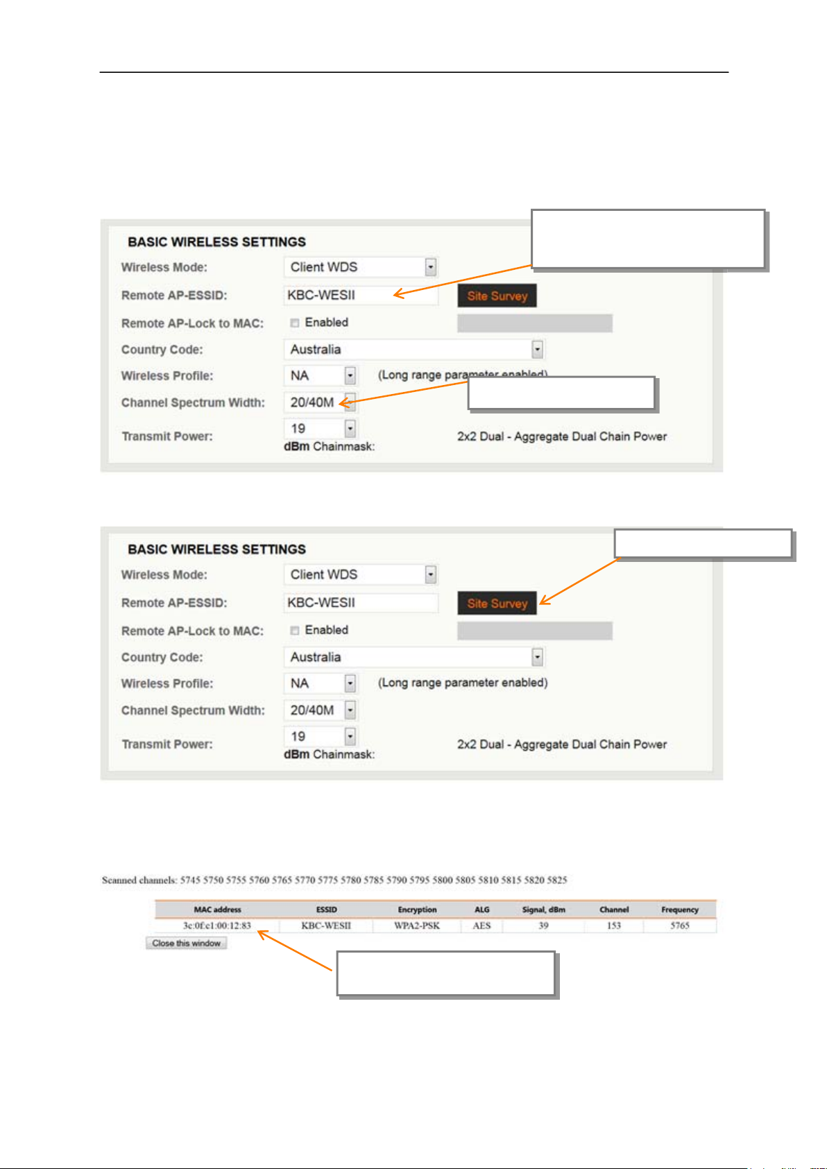
WES2HT User Manual
to.
Step 9: Ensure that the Channel Spectrum Width is on 20/40M & ensure that the
Remote AP-ESSID is set to the same as the Host unit for each of the Client
units in the group. For a site with multiple, point-to-multipoint systems
you will need to assign separate SSID for every group of Host plus Client
units.
Ensure this is the same as the
Host unit you want to connect
Ensure this is on 20/40M
Step 10: Select Site Survey to find the WES2HT Host you want to connect to.
Select: <Site Survey>
Step 11: The Site Survey will search for the KBC WES2HT Host that you want to
connect to. Click on the actual MAC address of the Host unit you want to
connect to.
Select: the MAC address eg.
3c:0f:c1:00:12:83
Manual-WES2HT-Rev1407-1
Copyright © KBC Networks 2013 Page 89 of 142
www.kbcnetworks.com

WES2HT User Manual
Step 12: The Host IP address should now appear in the Remote AP-Lock to MAC
address window. The Client unit will pick up the Host unit’s frequency automatically. You
now have a connected link.
Host MAC address selected that the
Client is now connected to.
Note: it is recommended that you write down all the MAC addresses and SSIDs used in
the application for future reference.
Step 13: The WES2HT units will take approximately 2 minutes to connect to each
other. Once a connection has been made the RSSI LEDs on the back of the
units will light to show the strength of the connection. See Section 7.
Step 14: Repeat the process for every Client that needs to be connected to the
Host.
Step 15: You will now be able to connect to the Host unit via the Client across the
link that has been set up. To do this open another tab on your web
browser and access the Host on its 192.169.1.200 default address.
Unless a more advanced set up is desired, the antennas are configured for installation at
this point. For advanced configuration see Section 11.
Manual-WES2HT-Rev1407-1
Copyright © KBC Networks 2013 Page 90 of 142
www.kbcnetworks.com

WES2HT User Manual
10 Installing on site
Once you are happy with the basic Host and Client(s) set up as described above the
units can be installed on site. It is recommended that all units are set up prior to
installation on site although frequencies may need to be adjusted if they have been
manually set if there is interference on certain channels. See pages 134-135 (Section
11.2.6.1 Interference Analyzer) for instructions of how to perform a frequency site
survey using the ‘Interference Analyzer’ tool on a Host unit to determine frequencies
already in use on a site.
10.1 Line-of-sight
It is important that there is proper line-of-sight between each Host and associated
Client(s). Line-of-sight is NOT just a single clear view running between the two points
like a laser beam. Line-of-sight includes the Fresnel Zone; think of being able to drive a
double decker bus between the two points without anything being in its path. If trees or
any other obstacle are blocking part of the Fresnel zone, the wireless system may not
transmit the signal the required distance.
In a situation like this, the transmit and receive antennas may need to be mounted on
higher poles to get above the trees or any other potential obstruction.
Manual-WES2HT-Rev1407-1
Copyright © KBC Networks 2013 Page 91 of 142
www.kbcnetworks.com

WES2HT User Manual
Range
Distance
1000 feet
305m
Required Fresnel
Zone Diameter
(2.4GHz)
20 feet
6.1m
Required Fresnel
Zone Diameter
(4.9/5GHz)
14 feet
4.3m
2500 feet
762m
1 mile
1.6km
4 miles
6.4km
10 miles
16.1km
30 miles
48.3km
33 feet
10.1m
47 feet
14.3m
92 feet
28m
148 feet
45.1m
20 feet
6.1m
30 feet
9.1m
60 feet
18.3m
100 feet
30.5m
N/A 200 feet
60.1m
Note: all measurements are estimated.
Manual-WES2HT-Rev1407-1
Copyright © KBC Networks 2013 Page 92 of 142
www.kbcnetworks.com

WES2HT User Manual
10.2 Spacing required when mounting WES2HT
units
See section 5 for mounting instructions. When mounting units in a relay configuration
the following distances between units are required.
Note: The operation of the units must be as depicted, failure to comply with these
instructions will invalidate warranty.
Manual-WES2HT-Rev1407-1
Copyright © KBC Networks 2013 Page 93 of 142
www.kbcnetworks.com

WES2HT User Manual
10.3 Cable lengths when installing WES2HT units
When installing the WES2HT units the total combined length of cables for any
configuration must not exceed 100m.
Note: The type of Cat5 configuration may be determined by the LAN port of the Ethernet
device. If the port is a 10/100 port, you may require a crossover cable. A crossover
cable is not necessary if the two PIMs connect into an Ethernet switch.
Most cables used to connect the WES2HT system are configured using a straight-through
color code.
Manual-WES2HT-Rev1407-1
Copyright © KBC Networks 2013 Page 94 of 142
www.kbcnetworks.com

WES2HT User Manual
10.4 Aligning the WES2HT units
For each WES2HT radio in the system, carry out the following steps:
Upon proper power via PIM or PSE device, the WES2HT unit’s power LED should
be green, ensure that the cable into the LAN port is seated properly.
Align the Client unit(s) to the Host unit so that they are pointing directly towards
each other.
The RSSI level of the link needs to be between 40 – 50dB if possible; to check
this either:
o Look on the back side of the WES2HT unit to determine the RSSI LED
status and re-position if necessary to obtain the best RSSI signal strength,
or
o On the Client unit in the ‘Status’ page of the GUI click on the <Align>
button to determine the RSSI level and re-position as necessary. For
further information see Section 11.2.1.5 Align.
10.5 Configuring IP addresses on a site
When installing multiple point-to-point or point-to-multipoint groups on one site, it is
important to ensure that each piece of equipment has a unique IP address. To change
the WES2HT unit’s IP addresses from their default (192.168.1.200 – Host, 192.168.1
201 – Client) see Section 11.2.6.1 Manual setting.
Manual-WES2HT-Rev1407-1
Copyright © KBC Networks 2013 Page 95 of 142
www.kbcnetworks.com

WES2HT User Manual
10.6 Replacing / Adding a WES2HT Module from/to the
Existing Application
10.6.1 Replacing a WES2HT Host unit
The WES2HT point to point Host/AP connects to its Client based on MAC Addresses. A
point-to-point Host/AP can connect to one Client MAC address only. A point-to-multipoint
Host/AP on the other hand can connect to multiple Clients but does not require MAC
address locking.
If a point to point Host/AP is being replaced, the Client with which it is required to
communicate must also be re-configured within the WES2HT Client’s Basic Wireless page
to ensure that the correct MAC address is selected for the new Host/AP.
Note: The Client is not required to have its MAC Lock feature enabled, however, it is set
to its original host when ordered in a bundled point to point kit. In that case, the Client
would need to be re-configured for the new Host MAC or have that feature disabled.
In addition, if adding a new Host/AP to an existing application the new Host/AP must be
configured to an available frequency not being used by the existing system. And the
original Host/AP should be set to a static frequency if still set to “Auto”.
10.6.2 Replacing a WES2HT Client unit
If a Client is being replaced, or added to a point-to-multipoint network, it’s SSID,
Country Code and channel spectrum width settings must be configured to match the
Host/ AP configuration with which it wants to connect.
If a Client is being replaced in a point-to-point network see Section 9 to reconfigure the
link.
Manual-WES2HT-Rev1407-1
Copyright © KBC Networks 2013 Page 96 of 142 www.kbcnetworks.com

WES2HT User Manual
11 Graphical User Interface
The WES2HT Graphical User Interface can be accessed in the following ways:
connecting directly to the WES2HT unit through the PIM
connecting via PSE device (eg. Ethernet switch)
via a WES2HT point-to-multipoint Host/AP connection to a Client PC/laptop
over a WES2HT wireless connection
11.1 Connecting to the WES2HT GUI using a PC
11.1.1 Using the supplied power injector
Connect the first Ethernet straight through cable from the ‘IN’ on the PIM to either a
laptop or a PC LAN port.
Connect the second Ethernet straight through cable from ‘OUT’ on the same PIM to the
WES2HT Host LAN port.
Apply power to the PIM with the provided 24Vdc PSU, ensure that the green LED on the
PIM is illuminated. Allow 60 seconds for the unit to boot up.
See Section 7 for WES2HT LED boot up process.
Note: Due to various port types, a crossover Ethernet cable may be required between
the Ethernet device and ‘IN’ port on the PIM. KBC Networks recommends a crossover
cable be available during set up, trouble-shooting and maintenance of the system.
Manual-WES2HT-Rev1407-1
Copyright © KBC Networks 2013 Page 97 of 142
www.kbcnetworks.com

WES2HT User Manual
11.1.2 Using a PoE Switch / PSE Device
Connect an Ethernet cable from the PSE device (eg. Ethernet switch) to the LAN port of
the WES2HT unit.
Connect the second Ethernet straight through cable to either a laptop or a PC LAN port.
Apply power to the PSE device and allow 60 seconds for the unit to boot up.
See Section 7 for the WES2HT LED boot up process.
11.1.3 Accessing the GUI via a Web Browser
The computer used to access the WES2HT GUI must be set to a static IP address on the
same subnet as the WES2HT unit. The WES2HT default configuration is on the
192.168.1.x subnet (refer to any provided documentation for the exact IP address for
the individual unit) therefore the computer must also be set to a 192.168.1.x IP address
if the unit is still on its factory set configurations.
Once the computer’s IP address is confirmed, open a web browser such as MS Internet
Explorer® or Mozilla Firefox®. Type in the Host/AP (192.168.1.200 default) or Client
(192.168.1.201 default) IP address in the address bar at the top of the web browser. If
the IP is correct and the link activity is established, the browser will prompt you to enter
the User Name and Password. The User Name and Password are ‘admin’ / ‘admin’ (case
sensitive).
User Name: admin
Password: admin
Manual-WES2HT-Rev1407-1
Copyright © KBC Networks 2013 Page 98 of 142
www.kbcnetworks.com

WES2HT User Manual
11.2 WES2HT Menu Options
The WES2HT has the following menu options for United States &
Canada and EMEA firmware:
DIAGOSTICS
o Status
o Services
o Topology
NETWORK
o Basic Network
BASIC WIRELESS
o Radio 1
ADVANCED WIRELESS
o Radio 1
The WES2HT has the following menu options for Australian firmware:
DIAGOSTICS
o Status
o Services
o System
NETWORK
o Basic Network
o Basic Wireless
o Advanced Wireless
Manual-WES2HT-Rev1407-1
Copyright © KBC Networks 2013 Page 99 of 142
www.kbcnetworks.com
 Loading...