


MPEG4 IP Encoder
User Manual
ENC-A-W
EDKT-A-W

Encoder User Manual
TABLE OF CONTENTS
1 OVERVIEW .................................................................................. 3
1.1 Introduction ............................................................................................................................................ 3
1.2 Technical Specification ............................................................................................................................ 4
2 INSTALLATION ............................................................................. 6
2.1 Package Contents .................................................................................................................................... 6
2.2 Physical Connections and Description ..................................................................................................... 6
2.3 Product Deployment ............................................................................................................................... 9
3 GRAPHICAL USER INTERFACE ......................................................... 13
3.1 Accessing the ENC-A-W* Graphical User Interface (GUI) ...................................................................... 13
3.2 Initial GUI Access & Video Display ........................................................................................................ 15
3.3 Main Menu ........................................................................................................................................... 16
4 TROUBLESHOOTING .................................................................... 26
4.1 Visual Inspection ................................................................................................................................... 26
4.2 Test Cable Connections ......................................................................................................................... 26
4.3 Video Related Problems ........................................................................................................................ 27
4.4 PTZ Control ............................................................................................................................................ 26
4.5 Audio Issues .......................................................................................................................................... 27
4.6 Contact Closures ................................................................................................................................... 27
4.7 GUI Tools ............................................................................................................................................... 27
4.8 Contact KBC Technical Assistance ......................................................................................................... 28
5 WARRANTY ............................................................................... 29
5.1 Warranty Information ........................................................................................................................... 29
6 SAFETY, APPROVALS AND REGULATORY DOMAIN INFORMATION ................ 30
6.1 Safety Instruction .................................................................................................................................. 30
6.2 Regulatory Certifications....................................................................................................................... 30
7 INSTRUCTION OF DISASSEMBLY ...................................................... 31
ANNEX A - GENERAL PUBLIC LICENSE STATEMENT .................................... 32
Manual-MPEG4_ENCA-Rev1206
Copyright © KBC Networks 2011 Page 2 of 33 www.kbcnetworks.com

Encoder User Manual
1 Overview
1.1 Introduction
This manual covers the KBC MPEG4 Encoder video server. KBC Networks’ network
encoders are high performance video servers which support constant simplex video
streaming, bi-directional RS-422/485/232 data, stereo audio and digital input/output
contact closure. They are designed for use in a wide range of operating
temperatures in environmentally conditioned/enclosed indoor or outdoor
applications. The KBC Encoder has been specifically designed to convert constant
streaming composite video, as well as other analog signal types, to Ethernet format
in order to connect to an existing network, fiber media converter or wireless
Ethernet system such as the KBC WESII series. This manual covers all features and
operations of the encoder. The operations of the KBC Decoder are found within its
own operations manual.
Manual-MPEG4_ENCA-Rev1206
Copyright © KBC Networks 2011 Page 3 of 33 www.kbcnetworks.com

Encoder User Manual
ENC-A Specification
Standards
IEEE Standards
IEEE 802.3 10BASE-T
IEEE 802.3u 100BASE-TX
IEEE 802.3x Full Duplex
Image
Compression
MPEG-4
Digital Resolution
QCIF (160 x 112 – NTSC,
176 x 144 – PAL)
CIF (352 x 240 – NTSC,
352 x 288 – PAL)
D1* (720 x 480 – NTSC,
(720 x 576 – PAL)
Image Frame Rate
30 FPS full D1 resolution (NTSC)
25 FPS full D1 resolution (PAL)
Interface
LAN/WAN Port
RJ-45 (10/100base-T)
Serial Port
4 pin terminal block
(RS-232 / 422 / 485)
Mode switch selectable
Analog video input
Composite, BNC connector (NTSC, PAL)
Analog video output**
Composite, BNC connector (NTSC, PAL)
Audio Line Input
Compression: 8 kHz, Mono, PCM
Unbalanced, 1.4V pk-pk
1 Vrms, 3.5mm Phone Jack
Audio Line Output
Compression: 8 kHz, Mono, PCM
Unbalanced, 1.4V pk-pk
1 Vrms, 3.5mm Phone Jack
Digital Alarm I/O
6 pin terminal block
Connection Type
TTL 2 inputs, 2 outputs
Digital Alarm Input (DI)
To Trigger (low)
Logic level 0: 0 ~ 0.8V
Normal (high)
Logic level 1:2.31 ~ 5.3V
Digital Alarm Output (DO)
To Trigger (high)
Logic level 1: 2.8 ~ 3.3V
Normal (low)
Logic level 0:0 ~ 0.5V
General
Built-in web server and network
interface
Network
Protocol Supported
TCP, UDP, HTTP, PPPoE, DDNS, DHCP,
IGMP
QoS
Layer 2, 3
1.2 Technical Specification
* Denotes default configuration
** Video Out BNC is loop through from Video In composite signal
Manual-MPEG4_ENCA-Rev1206
Copyright © KBC Networks 2011 Page 4 of 33 www.kbcnetworks.com

Encoder User Manual
Software OS Supported
Win 2000, XP, 2003, Vista, 7
Security
Username / password
Mechanical
Physical
Metal housing, not weatherproof
Dimensions (L x W x H)
40 x 120 x 136 mm
(1.56 x 4.72 x 5.37 in)
Weight
0.37 kg
(12.9 oz)
Certification
CE, FCC Class B
Power
Power Requirements
12 Vdc @ 625mA, 7.5W
Power Supply
12 Vdc 1500mA, wall transformer
supplied
Environmental
Humidity
10% ~ 90%
Operating Temperature
-30° ~ +70 °C
(-22° ~ +158 °F)
Connectors
10/100 Electrical
1 x RJ45
Composite
2 x BNC
RS-422/485/232
4 ports of 6 pin terminal block (2 ports
for voltage in)
DI/DO
6 pin terminal block
Power
2 ports of RS Data 6 pin terminal block
Approvals
FCC Part 15 subpart C
IC ID# 7849A-N523ESD
CE
Class A
Manual-MPEG4_ENCA-Rev1206
Copyright © KBC Networks 2011 Page 5 of 33 www.kbcnetworks.com
Encoder User Manual
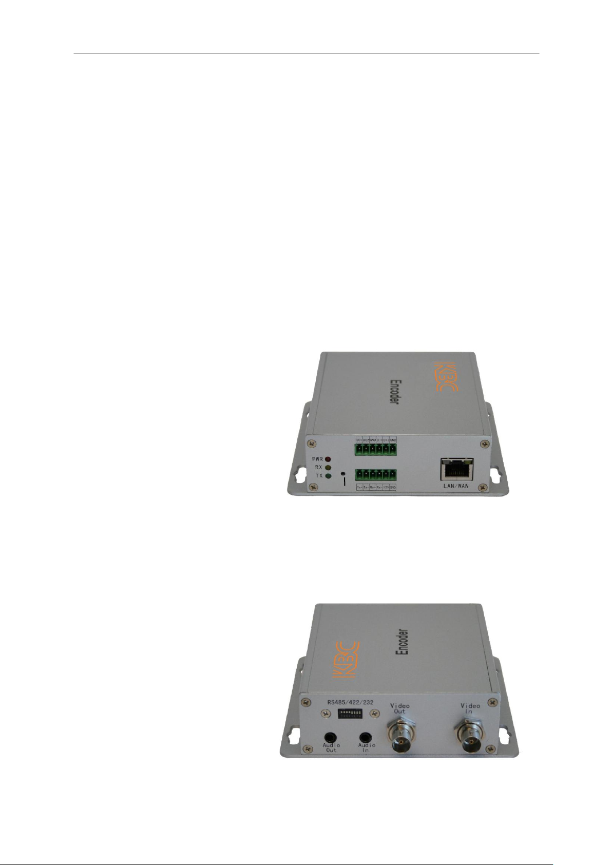
1. Power LED
2. Data RX LED
LED should only flash if receiving data from
connected data device. A solid RX LED
denotes a wiring error.
3. Data TX LED
LED should flash when transmitting data to
connected data device.
4. Reset to Default Configurations Button
(See section 2.2.3.1 for instruction and
results description)
5. DO1 and DO2 Alarm Input/Output
6. DI1 and DI2 Alarm Input/Output
7. RS Data Block
8. DC Voltage In
9. LAN/WAN Port, RJ-45 10/100Mbps
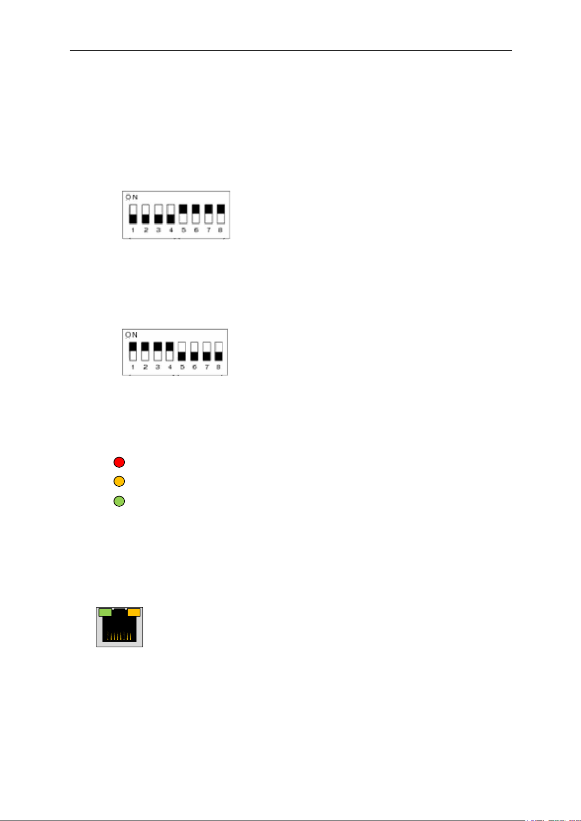
1. RS Data Selector Switch
Default Configuration: RS-485/422
2. Audio Out Mic/Speaker Jack
3. Audio In Mic/Speaker Jack
4. Video Out BNC
Video loop out from Video In source
5. Video In
Connect Video In prior to applying power
to Encoder. Power Cycle Encoder if video in
is connected after encoder is powered on.
1
2 3 4
5 6 7
8
9
1
2
3
4
5
2 Installation
2.1 Package Contents
One MPEG-4 Encoder
One 24Vdc, 500mA PSU for each power injector module included
Quick Start Guide
Consult the Quick Start Guide for the exact list of components for the particular part
number ordered. Please contact you dealer or distributor if a part is missing or
damaged within 10 days of receiving the products.
2.2 Physical Connections and Description
2.2.1 Front View
2.2.2 Rear View
Manual-MPEG4_ENCA-Rev1206
Copyright © KBC Networks 2011 Page 6 of 33 www.kbcnetworks.com
Encoder User Manual
PWR
TX
RX
3 1 2
4
5
White indicates the position of the switch
2.2.3 RS Protocol Dip Switch Selection
2.2.3.1 RS-422 / 485
The default configuration is set for RS-422 / 485. In the diagram below, white
represents the switch. The first four dip switches ON (in the up position) with the
last four OFF will set the encoder for RS-422 or 485 protocol.
Note: The dip switches will not determine the Baud Rate. The Baud Rate must be
configured to match the decoder, camera and PTZ system.
2.2.3.2 RS-232
The reverse dip switch positions (i.e, first four OFF and second four ON) will change
the encoder into RS-232 mode.
2.2.4 Status LED Description
The KBC Encoder offers status LEDs for the power and data as well as on the LAN
port for link status and activity.
2.2.4.1 Data TX/RX LEDs
1. Power LED. Allow 30 seconds after power up to illuminate steady.
2. Data RX. LED should remain OFF on standard activity. Will flash to
indicate that the camera is sending communication to the encoder.
3. Data TX. LED should remain OFF unless PTZ control signals are
being sent from the decoder (Transmitted to the camera).
Note: A solid RX LED indicates a data wiring, or other data related error. If the LED
will not turn OFF, contact KBC for further details and/or return authorization
for repair.
2.2.4.2 LAN / WAN Port
4. Link Status. On/Off
5. Port Activity. Will flash rapidly when streaming video.
Note: If the LAN port LEDs do not light up, check Ethernet cable or connected
Ethernet device.
2.2.5 Composite Video Connection
Make all Video In coaxial connections prior to powering up the encoder. If the video
input is connected after power is applied to the encoder, the unit will require a power
Manual-MPEG4_ENCA-Rev1206
Copyright © KBC Networks 2011 Page 7 of 33 www.kbcnetworks.com

Encoder User Manual
reset in order to stream video to a connected decoder and/or via the encoder GUI
video display.
The Video Out Composite BNC is an analog video loop through from the Video In
BNC. This provides an option to test the video out from a camera without
disconnecting the encoder and requiring a power reset to the encoder. Viewing video
from the Video Out BNC will not identify whether the encoder is actually encoding
the video, however, the encoder must be powered up to view the video from the
Video Out composite BNC. A video cable can be connected from the Video Out BNC
to a monitor after the encoder has been powered up without requiring a power
reset.
Note: If the connected camera loses power but the encoder does not, the encoder
must be power reset once the camera is back online.
2.2.6 Data Protocol Dip Switch Selection & PTZ Wiring Schemes
The following PTZ data schemes have been tested by KBC. Other wiring
combinations are possible depending on the PTZ system manufacturer.
Note: A solid RX light indicates an improper data wiring connection. If one of the
following schemes results in a solid RX LED, check the protocol dip switch
selection and/or use a varying wiring combination if your PTZ system requires
a different wiring solution.
2.2.6.1 RS-422/485, 2-wires
(Use default RS-422/485 dip switch selection)
From encoder: TX+ to camera: RX+ (or “A”)
From encoder: TX- to camera: RX- (or “B”)
2.2.6.2 RS-422, 4-wires
(Use default RS-422/485 dip switch selection)
From encoder: TX+ to camera: TX+
From encoder: TX- to camera: TX-
From encoder: RX+ to camera: RX+
From encoder: RX- to camera: RX-
2.2.6.3 RS-232
(Use RS-232 dip switch selection)
From encoder: TX+ to camera: Transmit
From encoder: RX+ to camera: Receive
From encoder: GND to camera: Ground
2.2.6.4 Known Incompatible Protocols
The following data protocols are not supported by the KBC encoder/decoder:
Sensornet
Biphase & Bilinx, other Bosch proprietary protocols
Kalatel protocols using RS-422. The system is compatible in RS-485 at 9600
Baud Rate
Coaxitron or any “up the coax” PTZ control systems
2.2.7 Bi-Directional Audio Parameters
2.2.7.1 Needed Audio Equipment
The mic/speaker audio in/out jack must be connected via stereo cable.
The audio source for Audio In must be amplified; the encoder does not
provide amplification on the audio.
Manual-MPEG4_ENCA-Rev1206
Copyright © KBC Networks 2011 Page 8 of 33 www.kbcnetworks.com

Encoder User Manual
Contact Closure Specification
DI
Connection Design
TTL-compatible logic
levels
Voltage
Trigger
(low)
Logic level 0: 0V ~
0.4V
Normal
(high)
Logic level 1: 3.1V ~
30V
Current
10mA ~ 100mA
DO
Connection Design
TTL-compatible logic
levels
Voltage
Trigger
(high)
Logic level 0: 2.4V ~
5V
Normal
(low)
Logic level 1: 0.1V ~
0.6V
Current
50mA
ENC-A-W* Encoder (ENC)
Action
DEC-A-W* Decoder (DEC)
DO1
DO2
DI1
DI2
DO1
DO2
DI1
DI2
ON
ON
ON
ON
Normal State
OFF
OFF
ON
ON
OFF
ON
ON
ON
Short DEC DI1 to GND
GND
ON
OFF
ON
ON
Short DEC DI2 to GND
GND
GND
Short ENC DI1 to GND
ON
OFF
ON
ON GND
Short ENC DI2 to GND
OFF
ON
ON
ON
LAN/WAN IP Address
192.168.1.100
LAN/WAN Subnet Mask
255.255.255.0
Gateway IP Address
192.168.1.254
GUI Access User Account ID
admin
GUI Access Password
admin
Audio In
Disabled
Data Protocol Selection (Dip Switch)
RS-422/485
Video Compression Type
MPEG-4
2.2.7.2 Default Audio Configuration
The audio is default configured as disabled and must be enabled in the encoder for
audio in. Audio out does not have a selection, simply connect a speaker to the Audio
Out jack and ensure that the decoder Audio In is enabled.
2.2.8 Alarm Input / Output Parameters
2.2.8.1 Voltage Specification
2.2.8.2 Trigger/Normal State Response
ON: Voltage present on port
OFF: Voltage is 0V
GND: Alarm trigger device causes DO/DI to short, turning off opposite DO / DI port
Note: Triggers from default configurations shown. See Decoder Interface settings to
configure other trigger options.
2.3 Product Deployment
2.3.1 Product Default Configuration Settings
2.3.1.1 Operations Manual Defaults
When an encoder is shipped from the KBC product warehouse, the default
configurations are as follows:
Manual-MPEG4_ENCA-Rev1206
Copyright © KBC Networks 2011 Page 9 of 33 www.kbcnetworks.com

Encoder User Manual
Video Streaming Method
TCP
Video Resolution
D1, 720 x 480 (NTSC)
Frame Rate & Mode
30 FPS, Constant
Video Bit Rate & Mode
1.2 Mbps, Constant
Serial Port Baud Rate
9600 BPS
Serial Port Control
8, None, 1
Video Control Port
6001
Video Streaming Port
6002
LAN/WAN IP Address
192.168.0.100
LAN/WAN Subnet Mask
255.255.255.0
Gateway IP Address
192.168.0.254
GUI Access User Account ID
admin
GUI Access Password
123456
Audio In
Disabled
Data Protocol Selection (Dip Switch)
RS-422/485
Video Compression Type
MPEG-4
Video Streaming Method
TCP
Video Resolution
D1, 720 x 480 (NTSC)
Frame Rate & Mode
30 FPS, Constant
Video Bit Rate & Mode
1.2 Mbps, Constant
Serial Port Baud Rate
9600 BPS
Serial Port Control
8, None, 1
Video Control Port
6001
Video Streaming Port
6002
2.3.1.2 Factory Defaults
When the reset button on the face of the unit is pressed, or a reset is performed
form the product interface, the parameters of the encoder will become (differences
from manual settings in italics):
2.3.2 Bench Test Set Up
KBC Networks recommends that all equipment be bench tested before being installed on
site. One crossover Ethernet cable is required.
1. Remove the encoder and/or decoder from box. The encoder IP address is factory
set to 192.168.1.100, the decoder IP address is factory set to 192.168.1.101
unless otherwise noted on provided documentation. The IP addresses do not
need to be changed for the units to operate individually or as a system. If you
will be using multiple encoder and decoder in a system, please see the advanced
operation section of this manual for setup. The encoder and decoder operate as a
pair and the IP addresses have been set accordingly.
2. Mount the encoder at the desired location. The encoder is not weatherproof and
will need to be mounted in a suitable environmental enclosure if used outside or
in a harsh environment. If the encoder is part of the Encoder/Decoder Kit (EDKTA-W), the included KBC housing is suitable for outdoor and/or harsh
environments provided the minimum and maximum temperature specifications of
the encooder are not exceeded.
3. Connect the analog video cable from the analog video source to the VIDEO-IN
port. If the system requires data transmission (pan/tilt/zoom or other
RS485/422/232 data) connect the wires from the data device the RS485/422/232
Tx+, Tx-, Rx+ & Rx- ports. If the system requires alarm communication and/or
audio, connect alarm device wires to the Digital Input (DI) ports and
mic/speakers to in/out ports.
4. Connect the LAN/WAN port of the encoder to the wired or wireless network. The
green LED on the front on the encoder will illuminate if the encoder is connected
Manual-MPEG4_ENCA-Rev1206
Copyright © KBC Networks 2011 Page 10 of 33 www.kbcnetworks.com

Encoder User Manual
Figure #1
Encoder and brace
assembly
* LWE-ED Enclosure is included with EDKT-A-W and WESII-KT-ED system
kits.
to a valid network/Ethernet device. If connected to a switch or KBC WES system
then a straight through cable is needed for this connection. If the encoder and
decoder are being tested back to back or through a KBC Mesh system, a
crossover cable will be needed.
5. Mount the DEC-A at the desired location. The decoder is not weatherproof and
will need to be mounted in a suitable environmental enclosure if used outside or
in a harsh environment. Typically the decoder will be located in close proximity to
the analog video device it will be connected to such as a monitor, DVR,
muliplexer, etc.
6. Connect an analog video cable from the Composite BNC output on the decoder to
the input of the analog device it will be connected to. If the system requires data
transmission (pan/tilt/zoom or other RS485/422/232 data) connect the wires
from the control device to the RS485/422/232 Tx+, Tx-, Rx+ & Rx- ports. If the
system requires alarm communication and/or audio, connect alarm device wires
to the Digital Input (DI) ports and mic/speakers to in/out ports.
7. Connect the LAN/WAN port of the decoder to a wired or wireless network. The
green and amber LEDs of the LAN port will illuminate if the DEC-A is connected to
a valid network/Ethernet device. If connected to a switch or wireless system then
a straight through cable is needed for this connection. When the encoder has
established communication with the decoder, The green LED on the encoder and
the amber LED on the decoder will flash rapidly. Analog video from the analog
video source connected to the encoder will be displayed on the device the
Composite output of the decoder is connected to.
2.3.3 Mounting the Encoder in a KBC LWE-ED enclosure*
See instructions included with enclosure for parts list and dimensions.
1. Attach KBC Encoder to mounting braces using self-thread Philips screws. Ensure
top and bottom holes are positioned at the outside corners and leave connection
loose to be able to screw into the housing. See Figure #1. Mount the Encoder
and brace assembly into the enclosure using four M5 x .9P x 10mm Philips pan
head screws. Tighten all eight screws. Attach the enclosure to a wall or pole (Pole
mounting hardware included).
2. Remove green connector from Encoder power supply in order to feed the cable
through the weatherproof plugs. Remove the black grommet from the white plug
and insert the power cable through the weatherproof plug. Reattach grommet
into plug and green connector onto power supply. Ensure white dashed cable is
inserted into 12V port and solid black cable into GRD port. If using a D900
Transceiver, place the transceiver on its side and adjust the antenna so it is
pointing up.
Manual-MPEG4_ENCA-Rev1206
Copyright © KBC Networks 2011 Page 11 of 33 www.kbcnetworks.com

Encoder User Manual
Side view of
mounted enclosure
Front view of
mounted enclosure
3. Attach an off-white painted bracket to the top and bottom of the enclosure. Use
four M5 x .9P x 10mm Philips pan head screws attaching the outer holes to the
four corner threaded ports on the backside of the enclosure. Mount enclosure to
pole or wall using two off-white painted brackets and hardware kit.
2.3.4 Replacing / Adding an Encoder to an Existing Encoder/Decoder
System
When a replacement encoder is ordered after the original products had been in
deployment, the new encoder may need to be reconfigured if the old device was not
set to the product defaults. The KBC Encoder can also replace an SED series encoder
and connect to an SED series decoder if applicable. If an SED series decoder is in
use the easiest reconfiguration is to set the new encoder to the settings of the old
SED series encoder which is no longer in use. Because the decoder must be told the
LAN IP and user ID and password of the encoder in order to stream its video, the
encoder may need to have its ID and password for GUI access changed as well.
Contact KBC for further details on this process.
2.3.5 Establishing a Connection to a KBC Decoder
When connecting the encoder to a KBC Decoder, the following items must be in
place:
Both of the LEDs on the encoder and decoder LAN port must be illuminated. When
video is streaming, the amber LED will flash rapidly.
Ensure that the video cable from the camera to the encoder is connected when
the encoder is powered down. Connecting it after encoder power up will require a
power reset.
The video source must be present and powered up. This can be verified using the
encoder Video Out composite BNC.
The encoder IP must be able to be pinged from the decoder side of the network
using a computer which is on the same subnet as the encoder/decoder devices.
The decoder must also be able to be pinged from the encoder side of the network
using a computer on the same static subnet as the encoder and decoder.
There must be sufficient throughput across the medium used to connect the two
devices. If insufficient throughput is available, the encoder can be reconfigured to
consume less network traffic.
The encoder and decoder must have their own individual network settings (i.e,
LAN or WAN IP, etc.)
The decoder must be configured properly in its “Connection Settings”
configuration screen to identify the appropriate encoder settings in order to
connect and stream the data from the encoder.
Note: If a connection to a KBC Decoder cannot be established in the field or on a
network, KBC recommends a test with the encoder directly connected to its
Manual-MPEG4_ENCA-Rev1206
Copyright © KBC Networks 2011 Page 12 of 33 www.kbcnetworks.com

Encoder User Manual
CPU
Pentium 4 2.4GHz and above
Memory
256 MB or above
Operating System
Windows XP with SP2 or above. Windows Vista / Win
2003 / Win7
Web Browser
IE 6.0 SP2 / IE 7.0 / IE 8.0
Video Resolution
SVGA or XGA with 1024 x 768 resolution
mate decoder using a crossover cable. If the two units are connected via an
unmanaged switch then the interface screen can be accessed from a web
browser in order to identify if a problem in configuration exists.
2.3.6 IP Utility Locating Software Tool
KBC Networks provides a software tool to search for the encoder and decoder IP
addresses. This tool is helpful for diagnostics and trouble-shooting if needed in the
installation. Visit KBC Networks’ website software tool at
www.kbcnetworks.com/downloads and select “Software”. The needed tool is the IP
Utility, the second link on the software downloads page. The other tools listed on the
page are for other KBC products which may not apply to your application.
3 Graphical User Interface
3.1 Accessing the ENC-A-W* Graphical User Interface (GUI)
The ENC-A series provides a web browser based configuration system accessible by
either connecting directly to the encoder, via a network link or over a wireless
Ethernet connection such as the KBC WESII series products. The web browser GUI
is accessible via a computer set to the same static subnet as the encoder. See
section 3.1.1.1 below to ensure that your computer Operating System is supported.
3.1.1 Connecting to the ENC-A-W* GUI using a PC
Connect a crossover Ethernet cable from a computer’s LAN port to the LAN/WAN
port of the encoder. After applying power the red Power LED will light up and then
turn back off during its power boot up. Verify that the red Power LED has reilluminated after the initial boot up, this can take up to a minute or more.
3.1.1.1 Minimum System Requirements
Manual-MPEG4_ENCA-Rev1206
Copyright © KBC Networks 2011 Page 13 of 33 www.kbcnetworks.com

Encoder User Manual
admin
3.1.2 Accessing the GUI via a Web Browser
The computer used to access the encoder GUI must be set to a static IP address on
the same subnet as the encoder. The default configuration is on the 192.168.1.x
subnet (refer to provided documentation for exact IP per unit Serial Number)
therefore the computer must also be set to a 192.168.1.x IP address if the unit is
still on its factory set configurations.
Once the computer’s IP address is confirmed, open a web browser such as MS
Internet Explorer®. Type in the encoder IP address in the address bar at the top of
the web browser. If the IP is correct and the link activity is established, the browser
will prompt you to enter the user ID and password. The ID and password is
“admin” / “admin” (case sensitive).
3.1.2.1 Language Options
The following Language Options exist for the user interface:
English (default)
Traditional Chinese
Simplified Chinese
Japanese
Spanish
Italian
German
Portuguese
Czech
French
Finnish
Hungarian
Danish
Note: Pull down menu options on configuration screens remain in English.
Note: The language option chosen from the account ID / password login will remain
Manual-MPEG4_ENCA-Rev1206
Copyright © KBC Networks 2011 Page 14 of 33 www.kbcnetworks.com

Encoder User Manual
only for the duration of the login period. The next login visit will revert to the
selected language from the Host Setting configuration page.
3.1.2.2 Reset
The reset button will clear whatever is entered for the account and/or password
entries. This will not reset the account ID and password to default configuration.
3.1.2.3 Login
Click the Login button to access the user interface. Upon a successful log in, the
camera video display will appear.
3.2 Initial GUI Access & Video Display
The encoder GUI immediately opens to the web browser video display. To access the
main menu for configuration changes, click “Set Up”
3.2.1 Streaming Options
MPEG-4 and MJPEG are the two compression type options available to stream the
video. The encoder will begin to stream with the new compression method as soon
as the type is selected.
Click “>>Setup” to exit the live view and access the main menu.
Manual-MPEG4_ENCA-Rev1206
Copyright © KBC Networks 2011 Page 15 of 33 www.kbcnetworks.com

Encoder User Manual
3.3 Main Menu
The main Setup page displays the directory of configuration options and tools.
3.3.1 Video Display
See section 3.2 for video display description. This link returns the user back to the
opening video display viewed after accessing the GUI.
3.3.2 Host Setting
The Host Settings are the general configurations of the encoder used for
identification and network association.
3.3.2.1 Host Name
Enter a host name for the encoder and it will be identified when the IP Utility is
used. The host name can be anything that will help to determine the camera when
the need to bring up the video or make configuration changes arises. Clicking reset
will clear the text from the host name section.
Manual-MPEG4_ENCA-Rev1206
Copyright © KBC Networks 2011 Page 16 of 33 www.kbcnetworks.com

Encoder User Manual
3.3.2.2 Language
See section 3.1.2.1 for language options. It is in this section where the selected
language will remain even after logging out.
Note: If the parameters of sections 3.3.2.1 and 3.3.2.2 have been changed from
default, you must click “Apply” to save those changes. The encoder must also
go through a reboot process by clicking on “>>Save Reboot” from the menu on
the left of the web browser.
3.3.2.3 Network Link Speed & Duplex
If a certain speed and duplex setting is required other than auto-detect, it can be
selected in this section. Other options include:
100 Mbps / Full Duplex
100 Mbps / Half Duplex
10 Mbps / Full Duplex
10 Mbps / Half Duplex
Note: If the Network Link Speed & Duplex parameters have been changed from
default configuration, you must click “Apply” to save those changes. The
encoder must also go through a reboot process by clicking on “>>Save Reboot”
from the menu on the left of the web browser.
3.3.2.4 Type of Service
The TOS tag priority can be added to the streaming. The options are:
Normal-Service (default configuration)
Minimize-Cost
Maximize-Reliability
Maximize-Throughput
Minimize-Delay
Note: Click on “Apply” in this section of the web browser GUI to apply changes to the
type of service.
3.3.2.5 Port Mapping
Select the port for this encoder to use HTTP protocol.
Select the first port on which software applications, such as the IP Utility, can
locate this encoder.
Select the second port on which software application, such as the IP Utility, can
locate this encoder.
Note: Click on “Apply” in this section of the web browser GUI to apply changes to the
port mapping.
3.3.3 WAN Setting
The WAN Setting is where the network properties of the encoder are configured.
Keep a record of changes or use the IP Utility to find the IP addresses if changed
from default configurations.
3.3.3.1 Dynamic IP Address
When selected the IP address of the encoder will be set automatically provided that
the encoder is connected to a DHCP router.
3.3.3.2 Static IP Address
KBC recommends selecting a static IP on the network. Advise the network
administrator for available static IP addresses prior to configuring the encoder on the
local network.
Manual-MPEG4_ENCA-Rev1206
Copyright © KBC Networks 2011 Page 17 of 33 www.kbcnetworks.com

Encoder User Manual
3.3.3.3 PPPoE
PPPoE is used when the encoder is connected directly to the xDSL modem.
User Name: enter the user name of the xDSL account
Password: enter the password for your xDSL account.
Clicking apply will force a “Save Reboot” process.
Note: Clicking “Apply” on this section after making changes to any of the network
information will force a “Save Reboot” prompt from the encoder.
3.3.3.4 DNS Server Setting
Primary DNS Server: defines the IP address of the primary DNS server in order to
identify the encoder by name instead of IP address.
Secondary DNS Server: Used as a fail over if the primary DNS server is not
available.
Note: Click on “Apply” in this section of the web browser GUI to apply changes to the
DNS Server Setting.
3.3.3.5 DDNS Server Setting
DDNS Type: Enable the encoder DDNS function to connect to the encoder by
domain name even if its IP address is not static
Service ISP: Select one of the DDNS service providers
Host name: Enter the host name of your DDNS service account (example:
Yourhostid.serviceprovider.extension).
User Name: Enter the login user name your would use to access your DDNS
service account (example: Your_username)
Password: Enter the login password you would use to access your DDNS service
account.
Note: Click on “Apply” in this section of the web browser GUI to apply changes to the
DDNS Server Setting.
3.3.4 Date Setting
The encoder can be custom configured to match the time and date of the users’
network via SNTP/NTP or manually. If your local area observes Day Light Saving,
you can program the encoder to automatically change its time when Day Light
Savings time begins and ends each year.
IP Address: Enter the IP
address of the SNTP/NTP
server.
Sync Time: Select the time
interval for the encoder to
synchronize its time.
Set Manually; Date: Select the
current date.
Set Manually; Time: Select the
current time.
Time Zone: Select the time
zone offset for local settings.
Day Light Saving; Start Time:
Select the appropriate date and
time when Day Light Savings
starts
End Time: Select the date and time when the time reverts to standard time.
Manual-MPEG4_ENCA-Rev1206
Copyright © KBC Networks 2011 Page 18 of 33 www.kbcnetworks.com

Encoder User Manual
Camera Name
Enter the particular camera number or a description
such as “North Lot” or “Main Gate”.
Streaming Method
Select the desired streaming mode. The options
available are:
- TCP Only
- Multicast Only
- RTP over Multicast
- RTP over UDP & Multicast
Note: video is displayed in the encoder interface in TCP
only. All other streaming methods must be viewed via
the decoder video output.
RTSP Authen
Enable
(appears when RTP
streaming methods
selected)
Check box to enable RTP streaming account/password
authentication
B2 Frame Enable
(appears when RTP
streaming methods
selected)
Check box to enable the B2 frame in RTP streaming
Audio In
Select to enable the audio in, default disabled.
Multicast IP
Select the multicast IP. Default is 228.5.6.1
Multicast TTL
Select the multicast TTL. Default is 255
IGMP
(appears only in
multicast)
Enable to use IGMP membership
3.3.5 Video Setting
Manual-MPEG4_ENCA-Rev1206
Copyright © KBC Networks 2011 Page 19 of 33 www.kbcnetworks.com

Encoder User Manual
Resolution
Select from the following options:
- QCIF
- CIF
- D1 (default)
Frame Rate Mode
Select from the following options:
- Constant (default): The streaming frame rate will
not vary regardless of conditions
- Variable: The streaming frame rate will vary
depending on condition of motion and change in the
video in order to maintain ideal image quality.
Frame Rate
Select the desired constant frame rate (not applicable in
Variable Frame Rate). Constant Frame Rate options
include:
- 30 FPS (default)
- 15 FPS
- 10 FPS
- 1 ~ 7 FPS
If Variable Frame Rate is selected, the following options
are available:
- 30 FPS
- 15 FPS
- 7 FPS
- 5 FPS
- 1 ~ 3 FPS
Encoder Type
Select the encoding compression type:
- MPEG-4 (default)
- MJPEG
Video Bitrate
Mode
If Variable Bit Rate is selected, video quality must also
be selected (Options: High, Middle, Low). Also input a
GOP Length which determines how many frames will be
sent in between each I Frame. If 0 is entered, only I
Frame will be transmitted each second.
Constant Bit Rate is the default setting.
Video Maximum
Bitrate
The range of the bit rate is from 28 Kbps up to 3 Mbps,
with “UNLIMITED” an option as well. The default setting
is 1.2 Mbps
Bitrate
Select the Bit Rate of the video streaming. A lower bit
rate consumes less bandwidth but will result in lower
quality images. A high bit rate will consume more
bandwidth with higher quality picture.
RTSP port
Select the port for the encoder to support RTSP.
Video RTP over
Multicast
Enable/disable the multicast video streaming via RTP
protocol.
Audio RTP over
Multicast
Enable/disable the multicast audio streaming via RTP
protocol.
Manual-MPEG4_ENCA-Rev1206
Copyright © KBC Networks 2011 Page 20 of 33 www.kbcnetworks.com

Encoder User Manual
Video Control Port
Select the port through which software applications may
control this encoder.
Video Streaming
Port (TCP Only)
Select the port through which software applications may
establish video streaming with this encoder.
Video Multicast
Port (Multicast
Only)
Select the port for this encoder to support video
multicast function of the application program.
Note: GOP length refers to the video frames between one completely encoded I frame
and other compressed P frames. The GOP length is usually equal to the number
of frames in one second. Using longer GOP length may save bandwidth
consumption, however at a risk of losing a portion of one GOP should the
network drop frames before the video refreshes. Long GOP is available only in
Constant FPS mode and variable Bit Rate in MPEG-4
3.3.6 Video Adjustment
The video adjust section of the user interface allows fine tuning to the web browser
video display. By clicking “Motion Enable” the user can also set motion trigger
parameters.
Select the desired brightness, saturation and contrast levels by either selecting from
the pull down menu or clicking on the blue bar. The video will adjust upon selecting
the desired level. Within the Activity window, the red line shows the baseline activity
level of the trigger threshold for the Runtime MD profile while a blue line records the
minimum activity for the Event MD profile. When the activity goes beyond the
minimum (red and blue lines), the various triggers will respond. Configure these
layers by clicking on “Motion Enable”
Three different regions can be set for enabling motion detection. Within each region,
the user can set the sensitivity, interval and threshold of the trigger. These values
can be set the same for each region or can be switched between Runtime Profile and
Event Profile via the Event handler.
Manual-MPEG4_ENCA-Rev1206
Copyright © KBC Networks 2011 Page 21 of 33 www.kbcnetworks.com

Encoder User Manual
Motion Detection Defined
The motion detection determines whether the amount of motion in a target region
exceeds the desired threshold. If the motion rises above the threshold it will trigger
the motion detection.
Sensitivity: When a sensitivity value is entered, the given value will determine
whether the pixel is considered to have motion activity. The higher the value
entered, the more that same motion sequence will be considered as motion
resulting in a triggered motion detection. In cases where there is little light, it is
suggested to reduce sensitivity in order to prevent overreaction to background
noise.
Threshold: This value decides the percentage of pixels to be marked as “changed”
in order to trigger a motion event. A smaller threshold will result in the encoder
responding to movement by smaller objects or even natural background noise.
The default value is 10; increase to filter out smaller objects.
Interval: The amount of time that must pass before another motion event can be
detected. This is used to prevent the encoder from generating too many motion
detection signals.
Noisy Environments: The background noise will be greater and can cause non-
existent motion activity. In this case, lower the sensitivity level and reduce the
threshold.
Object Size: Generally a smaller target region will be more accurate and sensitive
than a bigger region. It is best to cover the capture area with two or all three MD
regions rather than one large section covering the majority of the streaming
video.
3.3.7 OSD/Privacy Mask
To enable, click the “Enable” box. OSD, or On Screen Display, or Privacy Mask can be
selected. The privacy mask will place a color box over the desired area in order to
prevent the area from being seen on the encoder web browser video display. The
redacted display will also be presented on the video output when connected to a KBC
Decoder. When the OSD is selected, the format parameters must match the format
notice. At that point whatever is written into the “String” area will appear on the
video display. This text will not be displayed by the decoder video output.
3.3.8 SNMP Setting
Click to enable V1/V2 SNMP support or select SNMP V3 to support Version 3.
3.3.9 UPnP
Click to enable UPnP and enter the UPnP Friendly Name.
3.3.10 Bonjour
Click to enable Bonjour and enter Bonjour Friendly Name.
3.3.11 IP Address Filtering
The encoder can deny or allow certain IP addresses in order to filter network traffic
coming into the device. In “Allow” mode, the encoder will filter all IP addresses other
than the list of allowed IP addresses. All IP addresses that the encoder must listen
for must be listed manually. In “Block” mode, the user lists the IP addresses not
allowed and the encoder will allow all other IPs.
Note: Configuration of this option must be performed with care. If the IP address of
you computer is not listed in the “Allow” (or is listed in the “Block” list) you will
be denied access from the encoder web browser GUI. An incorrect configuration
may result in the need for a hard reset to factory default.
Manual-MPEG4_ENCA-Rev1206
Copyright © KBC Networks 2011 Page 22 of 33 www.kbcnetworks.com

Encoder User Manual
3.3.12 Event
This section identifies how the encoder will respond to trigger situations. The user
can set up to 10 Event Rules per encoder. Each rule includes one single trigger and
one of many responses. Various types of servers can be utilized in order to configure
the encoder to send a response to the desired type of server in order to receive the
trigger information. Event Configurations and the Event List also can be configured
here to further custom configure the trigger alert system. The notification message
section is where the sort of alert type can be custom designed.
3.3.13 User Account
The Root account admin has access to all GUI configuration pages and ability to
make configuration changes. All other users defined in the “User Account” list have
video display access and can see the system info as well. User 1 through User 10 do
not have access to such places as the Video Settings or WAN Settings or any place
where configurations can be altered.
Note: If the administrator account and/or password are changed, the decoder must be
given that info in its “Connection Setting” configuration page. The encoder and
decoder account and password settings do not have to match.
Manual-MPEG4_ENCA-Rev1206
Copyright © KBC Networks 2011 Page 23 of 33 www.kbcnetworks.com

Encoder User Manual
3.3.14 System Info
This screen displays the general information on the encoder and its firmware.
3.3.15 Firmware
When “Firmware” is clicked, the interface will ask if you want to upgrade the
firmware. Clicking “Apply” will bring the user to the screen where the firmware files
will be input. Clicking “Apply” will not upgrade the firmware immediately as the
correct files must be found in order to upload. Clicking “Reset” will return to the
main menu. To upgrade, click “Apply” then click “Browse” to locate the two needed
files for firmware upgrade. You will require the images and md5 files in order to
successfully upgrade firmware. These files must be obtained from KBC and saved in
an accessible place to locate from the “Browse” button. Browse and locate then click
“Apply”. When the firmware begins to upload to the encoder, the LAN port activity
LED will flash rapidly and the encoder will display a process bar to indicate the
completion procedure. Do not turn off the encoder or disconnect the Ethernet cable
until after the GUI shows the process bar at 100%. The unit will then automatically
go through the reboot process. Expect the power LED to turn off and then reilluminate up to a minute later.
3.3.16 Profile
Profiles are sets of parameters that control the image sensor behavior if fine-tuning
is required for a particular environment. The profile is not updated as often as the
firmware image may go through various revisions but on occasion a profile update
may be available and is uploaded here. When updated, the progress bar will appear
and show the percentage of completion. The encoder will reboot on its own after
completion.
3.3.17 Factory Default
The encoder can be returned to factory defaults completely or you can save its
Manual-MPEG4_ENCA-Rev1206
Copyright © KBC Networks 2011 Page 24 of 33 www.kbcnetworks.com

Encoder User Manual
LAN/WAN IP Address
192.168.0.100
LAN/WAN Subnet Mask
255.255.255.0
Gateway IP Address
192.168.0.254
GUI Access User Account ID
admin
GUI Access Password
123456
Audio In
Disabled
Data Protocol Selection (Dip Switch)
RS-422/485
Video Compression Type
MPEG-4
Video Streaming Method
TCP
Video Resolution
D1, 720 x 480 (NTSC)
Frame Rate & Mode
30 FPS, Constant
Video Bit Rate & Mode
1.2 Mbps, Constant
Serial Port Baud Rate
9600 BPS
Serial Port Control
8, None, 1
Video Control Port
6001
Video Streaming Port
6002
WAN/LAN & other IP Settings. Click “Apply” to reset all (or all but WAN and HTTP
Settings if appropriate box is clicked) configurations to factory defaults.
3.3.17.1 Factory Default Configurations
If all settings are returned to default, the new configurations are as follows:
3.3.18 Save Reboot
This link must be clicked after all setting changes have been applied.
3.3.19 Logout
When this link is clicked, the system will log out without a “save/reboot” process and
will return the user to the account and password login prompt.
Manual-MPEG4_ENCA-Rev1206
Copyright © KBC Networks 2011 Page 25 of 33 www.kbcnetworks.com

Encoder User Manual
4 Troubleshooting
4.1 Visual Inspection
The encoder contains LEDs which can be used as “at a glance” diagnostics. Further
details are listed under section 2.2.4.1 and 2.2.4.2
4.2 Test Cable Connections
4.2.1 Determine Link Activity
If the LAN port LEDs are not illuminated, verify the cable and/or Ethernet device
which is connects to the encoder. If the Ethernet device is not powered on or is
exhibiting some link activity problem the LAN port will not light up. As a precaution,
re-test all Ethernet cables with a cable tester.
4.2.2 Verify Type of Cable Needed
Generally a straight-through Ethernet cable is required for most unmanaged
switches and computer connections. On occasion a crossover cable is required. KBC
recommends each type of Ethernet cable available. If the cable will be exposed to
the elements in order to connect to an outdoor wireless antenna, use only shielded
outdoor rated cabling. Always protect the cabling from sources of potential harmful
voltage surges.
4.3 Video Related Problems
If the encoder connects to a KBC Decoder which is not displaying a video output, the
following steps can be followed to check the encoder side of the link:
4.3.1 Check Camera Output
If there is a problem with the composite video output, the decoder will display the
same error message as if the link between the two devices was not established. The
encoder, however, will display a “Video Loss” message on a blue screen. The video
input can be checked by using the “Video Out” BNC connected to an analog monitor.
4.3.2 Ensure Video Connection Prior to Applying Power to the Encoder
Always connect the video in prior to applying power to the encoder. If the encoder is
powered up before the video connection is made, the encoder will need to be power
cycled.
4.3.3 Verify Video display within the Encoder GUI
The encoder shows the video from the camera on its video display. After accessing
the user interface (GUI), the video display is the first property shown after login. If
no video is shown on the encoder GUI video display then the encoder may not be
encoding the video and may need to be hard reset or returned to KBC for further
diagnostics. Other possibilities remain which can be further trouble-shot via KBC
technical assistance.
4.4 PTZ Control
If the camera will not respond to PTZ commands, check the following:
Manual-MPEG4_ENCA-Rev1206
Copyright © KBC Networks 2011 Page 26 of 33 www.kbcnetworks.com

Encoder User Manual
4.4.1 Check Serial Protocol and Wiring Format
Check the mode selection switch to ensure that it is set for the correct protocol. A
solid RX LED will appear if the switch is set for RS-232 but wired for RS-422/485.
See section 2.2.6 for the appropriate wiring schemes.
4.4.2 Ensure Matching Baud Rate
The encoder Baud Rate must match the decoder and all third party PTZ equipment.
Make sure that the camera / control system is set for 9600 BPS or set the encoder
for the correct Baud Rate needed.
4.5 Audio Issues
If the audio device is not producing audio, check the following:
4.5.1 Audio Input
Verify that the audio in and level are selected from the encoder Video Settings found
in its GUI. Ensure that a stereo cable is connected to the “Audio In” from an
amplified audio source.
4.5.2 Audio Output
Verify that the stereo cable is connected to the “Audio Out”. Check the decoder GUI
for the volume in selection and volume level.
4.6 Contact Closures
See section 2.2.8 for the specs of the alarm input and output parameters.
4.7 GUI Tools
Go to KBC Networks’ website to download the IP Utility tool to assist in diagnostics
of the encoder and decoder IP devices.
Manual-MPEG4_ENCA-Rev1206
Copyright © KBC Networks 2011 Page 27 of 33 www.kbcnetworks.com

Encoder User Manual
4.8 Contact KBC Technical Assistance
Below is the contact information for KBC:
Technical Support Availability
This manual is comprehensive to the extent that it will answer many of your
technical questions. Technical assistance is available should you require additional
assistance. KBC offers technical support over the phone or by way of e-mail to all
KBC integrators, dealers and end users of the encoder product.
Our technical support hotline is available during regular business hours, Monday
through Friday with the exception of public holidays. KBC will follow up on all
electronic inquiries before the end of the following business day.
NORTH AMERICA
888-366-4276: Monday – Friday 10am-8pm Eastern (7am-5pm Pacific)
techsupport@kbcnetworks.com: 24hr availability, response time varies
HAWAII & ALASKA / GUAM, PR & OTHER US TERRITORIES
949-297-4930: Monday – Friday 7am-5pm Pacific Time
techsupport@kbcnetworks.com: 24hr availability, response time varies
Note: the toll free 888# does not work from Alaska
CENTRAL / SOUTH AMERICA
latamtechsupport@kbcnetworks.com: 24hr availability, response time varies
ASIA
apactechsupport@kbcnetworks.com: 24hr availability, response time varies
SOUTH PACIFIC / PACIFIC ISLANDS
apactechsupport@kbcnetworks.com: 24hr availability, response time varies
EUROPE
+44(0)1622 618787: Monday – Friday 9am-5pm UK time
emeatechsupport@kbcnetworks.com: 24hr availability, response time varies
AFRICA & MIDDLE EAST
emeatechsupport@kbcnetworks.com: 24hr availability, response time varies
Technical Support is offered in English, however, KBC Networks has worldwide
representatives who can provide technical support in many local languages.
Note: technical assistance is available after having read through this manual.
Comprehension of terms and topics will assist in trouble-shoot procedures.
Manual-MPEG4_ENCA-Rev1206
Copyright © KBC Networks 2011 Page 28 of 33 www.kbcnetworks.com

Encoder User Manual
5 Warranty
5.1 Warranty Information
KBC extends the following LIMITED WARRANTY to the original owner/purchaser of
this product as follows:
- Two years from the date of initial sale for all wireless and network products.
- Five years from the date of initial sale for all fiber products.
1) If, within the specified warranty period, this product, or any part or portion thereof,
shall prove upon examination by KBC, to be defective in material or workmanship,
KBC will repair or replace such part or portion at KBC’s option. The warranty period
on the repaired or replaced part or portion of this product shall be limited to the
unexpired term of the original warranty. The buyer shall be responsible for all
shipping and transportation of the product to KBC for any performance under this
warranty.
2) Conditions and Exceptions:
a) Any accident to this product, any misuse or abuse, alternation, use in modified
form, or any attempt to repair this product shall void this warranty. These
conditions to the warranty include, but are not limited to, incorrect power
connections, physical damage due to mechanical shock, exposure to moisture,
and circuit modification.
b) SHOULD THIS PRODUCT PROVE DEFECTIVE FOLLOWING PURCHASE, THE BUYER,
NOT THE MANUFACTURER, DISTRIBUTOR, OR RETAILER, ASSUMES THE ENTIRE
COST OF ALL SERVICING OR REPAIR, EXCEPT AS OTHERWISE PROVIDED BY THE
TERMS OF THIS WARRANTY.
c) FOR BREACH OF ANY WRITTEN OR IMPLIED WARRANTY ON THIS PRODUCT, THE
BUYER IS LIMITED TO THE FOLLOWING DAMAGES. (1) THE COST OF LABOR TO
REPAIR OR REPLACE DEFECTIVE PARTS OR PORTIONS OF THIS PRODUCT, AND
(2) THE COST OF THE REPAIRED OR REPLACE PARTS OR PORTIONS OF THIS
PRODUCT.
d) NO OTHER EXPRESSED OR IMPLIED WARRANTIES HAVE BEEN MADE OR WILL BE
MADE ON BEHALF OF KBC WITH RESPECT TO THE SALE, REPAIR, INSTALLATION,
OPERATION, OR REPLACEMENT OF THIS PRODUCT. KBC DISCLAIMS ANY
IMPLIED WARRANTY OF MERCHANTABILITY OF THIS PRODUCT OR ITS FITNESS
FOR ANY PURPOSE, AND THE BUYER AGREES THAT THIS PRODUCT IS SOLD “AS
IS” AND THAT THE ENTIRE RISK OF QUALITY AND PERFORMANCE OF THIS
PRODUCT IS WITH THE BUYER, EXCEPT AS OTHERWISE PROVIDED BY THE
TERMS OF THIS WARRANTY.
e) Some states/jurisdictions do not allow exclusions or limitations of incidental or
consequential damages, or limitations on how long an implied warranty lasts, so
the above exclusions or limitations may not apply to you.
f) If you do not wish to be bound by any of the provisions in this warranty, please
return the product(s) immediately.
3) Contact your dealer regarding return authorizations for out of warranty repairs and
any further product information.
This warranty does not apply in Australia.
Manual-MPEG4_ENCA-Rev1206
Copyright © KBC Networks 2011 Page 29 of 33 www.kbcnetworks.com

Encoder User Manual
6 Safety, Approvals and Regulatory Domain
Information
6.1 Safety Instruction
For your protection, please read and observe all safety instructions before operating
this system and keep this sheet and any additional instructions for future reference.
6.1.1 Installation and Use
OBSERVE WARNINGS: All warnings in the operating instructions should be carefully
followed. Do not make any modifications to the encoder unit, power supply, or any
other KBC Networks electronic device, as the unit(s) will no longer comply with legal
regulations and therefore void its warranty.
WATER AND MOISTURE: The encoder is not weatherproof and must be mounted
indoors or in an outdoor protective enclosure.
POWER SOURCE: Connect the equipment to a power source only of the type
described on the operating instructions or as marked on the equipment. Excessive or
insufficient current or voltage can cause extended trouble-shooting or even damage
that could negate its warranty.
ATTACHMENTS: Use only KBC Networks’ supplied or recommended Power Supplies,
Power Injection Modules (when connecting to a KBC WESII or other KBC wireless
system), Cat5 Cables and weather seals (where applicable) and plugs.
WHEN NOT IN USE: Unplug the power if the equipment is left unattended or
unused for long periods of time or during lightning storms (if outdoors).
REPLACEMENT PARTS: When replacement parts are required, use only replacement
parts specified by KBC Networks. Unauthorized substitutions may result in damage to
the system and could void the warranty.
6.2 Regulatory Certifications
The KBC encoder is certified by FCC, IC, CE
6.2.1 FCC Part 15 Required Statement
This equipment has been tested and found to comply with the limits for a Class A
digital device, pursuant to Part 15 of the FCC Rules. These limits are designed to
provide reasonable protection against harmful interference when the equipment is
operated in a commercial environment. This equipment generates, uses, and can
radiate radio frequency energy and, if not installed and used in accordance with the
instruction manual, may cause harmful interference to radio communications.
Operation of this equipment in a residential area is likely to cause harmful
interference in which case the user will be required to correct the interference at his
own expense.
Manual-MPEG4_ENCA-Rev1206
Copyright © KBC Networks 2011 Page 30 of 33 www.kbcnetworks.com

Encoder User Manual
7 Instruction of Disassembly
Instruction of Disassembly of KBC Product
(For EU Directive 2002/95/EEC-WEEE)
Tools required:
No. 1 Phillips screwdriver
Steps for disassembly:
1. Remove screws from front face of encoder.
2. Slide out top lid
3. Remove screws from back end face of encoder.
4. Slide out printed circuit board (PCB).
Notice: When a product reaches the end of its life – return to KBC.
Manual-MPEG4_ENCA-Rev1206
Copyright © KBC Networks 2011 Page 31 of 33 www.kbcnetworks.com

Encoder User Manual
Annex A - General Public License
Statement
You may have received from KBC Networks products that contained – in part – free
software (software licensed in a way that ensures your freedom to run, copy,
distribute, study, change and improve the software). Such products include the ENCA-Wx family of products.
As part of these products, KBC Networks may have distributed to you hardware
and/or software that contained a version of free software programs developed by the
Free Software Foundation, a separate not-for-profit organization without any
affiliation to KBC Networks. See http://www.gnu.org/philosophy/free-sw.html for
more details. If KBC distributed any portions of these free software programs to
you, you were granted a license to that software under the terms of either the GNU
General Public License or GNU Lesser General Public License (“License”, copies of
which are available from http://www.gnu.org/licenses/licenses.html). The Licenses
allow you to freely copy, modify and redistribute that software without any other
statement or documentation from us.
For at least one (1) year from the date of distribution of the applicable product or
software, KBC Networks will provide to anyone who contacts us at the contact
information provided below, for a charge of no more than our cost of physically
performing source code distribution, a complete machine-readable copy of the
complete corresponding source code for the free software programs used in the
version of the programs that we distribute to you. The cost will be free if the delivery
medium of the machine-readable copy is through the Internet.
Contact information:
Email: techsupport@kbcnetworks.com
Tel: 949.297.4930
Address: 25691 Atlantic Ocean Drive Lake Forest, CA 92630
We do ask for your understanding regarding expected delivery timelines:
1. We will reply within 7 working days once the request has been made through
email/telephone.
2. The default version sent will be the latest that we used in the firmware/programs.
3. Note, it may take longer if an older version is requested. The waiting time will not
exceed 2 weeks.
Manual-MPEG4_ENCA-Rev1206
Copyright © KBC Networks 2011 Page 32 of 33 www.kbcnetworks.com

KBC Networks North America.
25691 Atlantic Ocean Drive
Suite 3B
Lake Forest, CA 92630
U.S.A
Americas
Phone: 1-949-297-4930
Fax: 1-949-297-4933
KBC Networks Ltd. EMEA
KBC Networks Ltd.
Barham Court
Teston, Maidstone
Kent, ME18 5BZ
United Kingdom
Phone: +44(0)1622 618787
Fax: +44(0)20 7100 8147
Email: info@kbcnetworks.com
Web: www.kbcnetworks.com
data delivered
Encoder User Manual
Manual-MPEG4_ENCA-Rev1206
Copyright © KBC Networks 2011 Page 33 of 33 www.kbcnetworks.com
 Loading...