

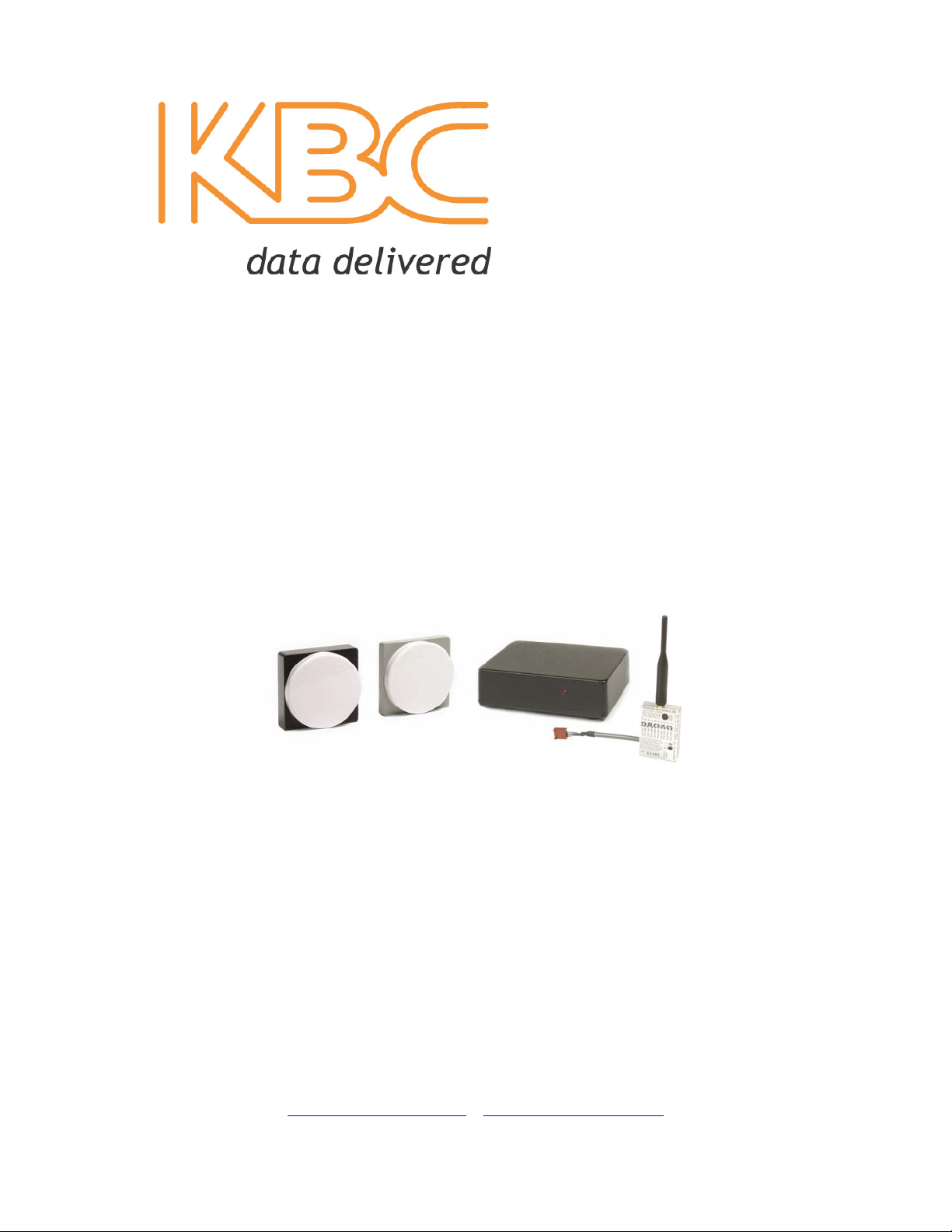
MiniLink®5.8GHzWirelessVideo/AudioSystems
OPERATIONSMANUAL
KBCNetworks
25691AtlanticOceanDrive,SuiteB‐3;LakeForest,CA92630
N.America:(949)297‐4930|EMEA:44(0)1622618787
www.kbcnetworks.com|info@kbcnetworks.com
VER 20090810

IMPORTANT SAFETY INFORMATION
For your protection, please read and observe all safety instructions before operating these products. Keep
this sheet and any additional instructions for future reference.
INSTALLATION & USE
• OBSERVE WARNINGS: All warnings in the operating instructions should be carefully
followed to avoid unnecessary damage to any of the products and to ensure the validity of
its warranty.
• WATER AND MOISTURE: Do not use or install this equipment near water. Severe
electrical shock, personal injury or damage to the equipment may result. The LNB
receive antenna is weatherproof provided the supplied weatherproof F Connectors are
used and tightened sufficiently. If one or more of the products, including the LNB, are
installed in a harsh environment a NEMA rated enclosure is required.
• HEAT: Do not install the equipment near heat sources such as radiators, stoves, heat
registers and other appliances that produce heat.
• POWER SOURCE: Connect the equipment to a power source only of the type described
on the operating instructions or as marked on the equipment.
• ATTACHMENTS: Use only KBC recommended attachments.
• WHEN NOT IN USE: Unplug the power if the equipment is left unattended or unused
for long periods of time or during lightning storms
• REPLACEMENT PARTS: Use only replacement parts specified by the manufacturer.
Unauthorized substitutions may result in fire, electrical shock or other hazards.
FCC NOTICE
This equipment has been tested and found to comply with the limits of a Class B device,
pursuant to PART 15C of the FCC Rules. These limits are designed to provide reasonable
protection against harmful interference.
This equipment generates, uses and can radiate radio frequency energy and, if not installed and
used in accordance with the instructions, may cause harmful interference to radio
communications. However, there is no guarantee that interference will not occur in a particular
installation. If this equipment does cause harmful interference to radio or television reception,
which can be determined by turning the equipment off and on, the user is encouraged to try to
correct the interference by one or more of the following measures:
• Reorient or relocate the receiving antenna.
• Increase the separation between the equipment and receiver.
• Connect the equipment into an outlet on a circuit different from that to which the receiver is
connected.
• Consult your dealer or an experienced radio/RF technician for help.
Any changes or modifications not expressly approved by the manufacturer could void the
user’s authority to operate the equipment.
INDUSTRY CANADA NOTICE
The term “IC:” before the certification/registration number only signifies that the Industry Canada
technical specifications were met.
Operation is subject to the following two conditions: (1) this device may not cause interference,
and (2) this device must accept any interference, including interference that may cause undesired
operation of the device.
- ( i ) -

INDEX
SECTION PAGE #
IMPORTANT SAFETY INSTRUCTIONS-------------- ( i )
FCC NOTICE-------------------------------------------------- ( i )
INDUSTRY CANADA NOTICE -------------------------- ( i )
QUICK START GUIDE------------------------------------- 2
PRE-INSTALLATION REMINDER--------------------- 3
RECEIVER DESCRIPTION ------------------------------ 4 - 5
FRONT VIEW ------------------------------------------------ 4
REAR VIEW -------------------------------------------------- 4
BOTTOM VIEW ---------------------------------------------- 4
WIRING DIAGRAM ----------------------------------------- 5
CABLING SPECIFICATIONS------------------------------ 5
RECEIVER OPERATION --------------------------------- 6 – 7
HOW TO SETUP THE RECEIVER ----------------------- 6
MAINTENANCE --------------------------------------------- 7
RECEIVER SPECIFICATIONS ------------------------- 7
LNB DESCRIPTION ---------------------------------------- 8
HOW TO SETUP THE LNB -------------------------------- 8
MAINTENANCE --------------------------------------------- 8
LNB SPECIFICATIONS ----------------------------------- 8
TRANSMITTER DESCRIPTION ------------------------ 9 - 11
DIRECTIONAL TRANSMITTER
FRONT VIEW ------------------------------------------------- 9
REAR VIEW --------------------------------------------------- 9
OMNI DIRECTIONAL TRANSMITTER
FRONT VIEW -------------------------------------------------- 9
TRANSMITTER OPERATION -------------------------- 10
HOW TO SETUP THE TRANSMITTER ----------------- 10
MAINTENANCE --------------------------------------------- 10
TRANSMITTER SPECIFICATIONS ------------------- 11
TROUBLE SHOOTING ------------------------------------ 12
WARRANTY INFORMATION---------------------------- 13
- 1 -

QUICK START GUIDE
KBC recommends that all equipment be bench tested before being installed onsite. This
test will ensure all necessary equipment is functioning properly.
TRANSMITTER SETUP
1. Remove Transmitter from box, select frequency and audio mode. (Factory set to channel
10)
2. Mount the transmitter at the desired transmit location. Position transmitter for desired
polarity using rear label arrow as a reference, transmitter and receiver polarity must
match one another.
3. Connect power, audio and video inputs to transmitter.
LNB SETUP
1. Remove LNB from box and mount at the desired receive location in line of site with the
transmitter. Position LNB for desired polarity using rear label arrow as a reference,
transmitter and LNB polarity must match one another. The LNB is weatherproof and
does not require additional housing unless mounted in a harsh environment.
2. Connect cable to the LNB. (Use only RG 6 coaxial cable with the supplied weatherproof
“F” connectors to connect Receiver and LNB. Cable length should be a minimum of 10
feet and a maximum of 100 feet.)
Note: If an 18” Parabolic Dish Antenna is used with the system (ML58-1, ML58-1M,
ML58-1E or ML58-1ME), assemble the dish and mount the LNB in the dish as described in
the dish installation instructions. Position the dish with LNB and connect the cab le to the
LNB as described above. It is recommended that the dish be mounted with at least fifteen feet
of clearance from ground level for one-mile range and directed in a downward angle for
optimal picture.
RECEIVER SETUP
1. Remove Receiver from box and position it at the desired receive location. The unit is
designed to be placed in the head end room along with the DVR and monitoring devices
and will not require an environmental housing if kept inside as in most cases.
2. Connect Quad-shielded RG 6 cable from the LNB to the antenna port F-Connector on the
back panel of the receiver.
3. Connect the audio and video outputs to a DVR, monitor or other device.
4. Connect the power using the included 12 VDC 500 mA power supply.
WARNING: MAKE ALL COAX CONNECTIONS WHILE THE RECEIVER IS
POWERED DOWN. CONNECTIONS MADE WHILE THE RECEIVER IS ON
COULD CAUSE DAMAGE TO THE UNIT.
Trouble Shooting: If video does not appear on the screen or you are having other operational
difficulties, please visit the trouble shooting section on page 15 of the operations manual or
contact KBC toll free Monday through Friday, 8-5pm PST at (888) 366-4276 for technical
assistance.
- 2 -

PRE-INSTALLATION REMINDERS
The information on the Quick Start Guide is intended for ease of use and application, the following
reminders will help to ensure your satisfaction with KBC products and service.
1. Read through this manual before bench testing and installation
2. Perform a bench test incorporating all components of the application
3. Install your MiniLink 5.8 GHz System
4. Toll-free technical assistance is available Monday through Friday (8-5pm PST) at 888-
366-4276
KBC ELECTRONICS RETURN POLICY
The MiniLink 5.8 GHz Analog Wireless Video/Audio Systems come with a 2-year limited
warranty for repair or replacement (see the last page for warranty information). In addition to the
2-year warranty, all products can be returned within the first thirty (30) days for credit. Products
may be returned within 30-days of shipment provided the products are in like new condition and
in the original packaging. Contact your KBC dealer or distributor to obtain an authorization to
return the merchandise for credit.
- 3 -

DESCRIPTIONS AND SPECIFICATIONS
MINILINK® 5.8 RECEIVER DESCRIPTION
FRONT AND REAR VIEWS
1
1. LED INDICATOR
Indicates power is on when illuminated
2. POWER INPUT
12VDC 440 mA. Power supply included.
3. RF INPUT
“F” connector, connection to LNB via RG6 coaxial cable.
4. AUDIO OUTPUT
Mono audio output to video monitor or DVR, use either right or left channel
5. VIDEO OUT
Supply filtered, clamped video output to video monitor or VCR.
6. VIDEO OUT
Supply filtered, clamped video output to video monitor or VCR.
BOTTOM VIEW
1
2
1. CHANNEL SELECT DIPSWITCH
Dip switch for selection channels 1 – 10. (Receiver and transmitter channels must
match). The Receiver is factory set to Channel 10
2. CHANNEL SELECT LABEL
Shows dip switch settings for channels 1 – 10.
6 5 4 3 2
- 4 -

RECEIVER DESCRIPTION (Continued)
b
WIRING DIAGRAM
IMPORTANT: Use only RG 6 coaxial cable
with the supplied weatherproof “F” connectors to
connect Receiver and LNB. Cable length should
e a minimum of 10 feet and not exceed 100 feet.
Audio Out RCA
DVR/Monitor Video In BNC
Extra Video Out BNC
E. CABLING SPECIFICATIONS
NOTE: Coaxial cables are not included in a MiniLink wireless system. Supplied for the installation are two
weatherproof F-Connectors which are to be crimped onto the RG 6 coaxial cable.
• RG 59 Coaxial Cable: Up to 500 feet (Use between Receiver and DVR/Monitor
as well on transmit end: between Camera and Transmitter)
• RG 6 Coaxial Cable: Up to 100 feet to be used between LNB receive antenna
typically mounted outdoors and Receiver located in the head end room.
• Given wide open line-of-sight and no 5 GHz interfering sources in a particular
environment, a MiniLink wireless system will transmit and receive the video
quality that is coming from the camera or over the cables connected to that
wireless system. Cables in poor condition or even insufficient crimping could
result in undesired operation. All crimps or other connections must be made using
industry standard tools. Also verify that all cables being used are free of cuts,
gouges, kinks, or bends that can have an effect on your video quality. A hardwire
set-up (without the wireless link) on a bench test will help to verify the above
suggestions.
• Power cables should be kept at their normal stock length to avoid problems that
may arise which could be outside of KBC technical support field of expertise.
However, if power cables must be extended for a particular application, KBC
does not suggest any wire lighter than 18-gauge in order to avoid voltage loss.
12VDC
Power
Supply
- 5 -
Audio source
Video source
Power input
Power indicator
Up to 1000 feet clear line-of-
sight using base range 1000’
system (as pictured)

RECEIVER OPERATION
A. RECEIVER SET UP
1. LOCATON
The Receiver is designed to be placed on a flat surface for stability. The Receiver is not
weatherproof and should be placed indoors or in an environmental enclosure if used
outdoors or in a harsh environment.
2. POWER
The Receiver is powered by a 10-14.5 VDC power supply connected to the Power In
connector on the rear of the case, incorporating internal reverse voltage protection. The
Receiver itself will draw 220 mA of power and the LNB, which gets its power from the
Receiver, uses 220 mA.
3. CHANNEL SELECT
Channel selection is accomplished by programming of the 4-position dipswitch located at
the rear panel. Match the dipswitches to the setting on the label for the desired channel
(Any numbers visible on the switch itself are not used. The white squares indicate the
switch location).
4. ORDER OF SETUP AND OPERATION
• Select Frequency (Factory set to channel 10)
WARNING: TO PREVENT DAMAGE TO THE RECEIVER, CONNECT THE
RECEIVER TO THE LNB BEFORE APPLYING POWER TO THE RECEIVER.
B. MAINTENANCE
Your KBC MiniLink product is an example of superior design and craftsmanship. The
following suggestions will help to ensure maximum operational life:
• Keep the product dry. If it does get wet, wipe it dry immediately. Liquids may contain
• Use the system only within the environmental specifications indicated. High
• Connect Power, Video and Audio outputs to receiver.
minerals than corrode electronic circuits.
temperatures can shorten the life of electronic devices and melt plastic parts. Excessive
mechanical shock can damage the case, connectors or internal circuit board.
- 6 -
NOTE: Dipswitch configurations for
each channel can vary between the
transmitter and receiver. Match the
dipswitch positions on each individual
unit in use with the drawing layout as
pictured on each unit for the desired
frequency channel.

RECEIVER SPECIFICATIONS
MINILINK® 5.8 RECEIVER
RF SECTION
Input Frequency Range 971 MHz to 1088 MHz
Frequency Control Synthesized PLL
Input Impedance 75 Ohms
IF Bandwidth 15 MHz
Static Threshold 6 dB (Typical)
Image Rejection 40 dB (Typical)
VIDEO SECTION
Format NTSC/PAL
DE-Emphasis CCIR 405-1
Frequency Response (3 dB) 50 Hz to 3.8 MHz
Output Level 1.0 V P-P +/- 5%
Output Impedance 75 Ohms
AUDIO SECTION
Sub-carrier Frequency 6.0 MHz
Bandwidth 150 KHz
Frequency Response (3 dB) 50 Hz to 18 KHz
Output Impedance 10 K Ohms (unbalanced)
MECHANICAL
Size 4.69”w x 4.38”d x 1.44”h
Weight 16 oz
POWER
Power Requirements 10-14.5 VDC @ 440 mA
Internally fused, reverse
voltage protected
ENVIRONMENTAL
Humidity 95% non-condensing
Operating Temperature -20F to +180F case temperature
*For product improvement, design and specifications are subject to change without notice.
(LNB power supplied by Receiver)
- 7 -

MINILINK® 5.8 LNB DESCRIPTION, OPERATION & SPECIFICATIONS
A. FRONT VIEW B. REAR VIEW
1. RF OUTPUT
Coaxial cable output to the receiver (971 – 1088 MHz). Power supplied to the LNB from receiver
through this cable at 9-16 VDC.
IMPORTANT: Use on ly RG 6 coaxial cable with the supplied waterproof “F” connectors to
connect Receiver and LNB. Cable lengths should be a minimum of 10 feet and a maximum of
100 feet.
WARNING:
POWERED DOWN. CONNECTIONS MADE WHILE THE RECEIVER IS ON COULD
CAUSE DAMAGE TO THE UNIT.
MAKE ALL COAX CONNECTIONS WHILE THE RECEIVER IS
LNB OPERATION
A. LOCATION / MOUNTING
Since the LNB is weatherproof, it can be wall or pole mounted using the equipment supplied with
environmental systems only. (MiniLink 5.8 model numbers with an “E” at the end are environmental
systems.) Contact KBC if you do not have wall/pole mounting hardware.
B. MAINTENANCE
Your KBC product is an example of superior design and craftsmanship. Use the system only
within the environmental specifications indicated. High temperatures can shorten the life of
electronic devices and melt plastic parts. Excessive mechanical shock can damage the case,
connectors or internal circuit board. Use the supplied weatherproof F-Connectors and crimp onto
the Quad-shielded RG 6 coaxial cable to ensure weatherproof mounting.
LNB SPECIFICATIONS
RF SECTION
LO Frequency 4770 MHz
IF Output 971 to 1088 MHz
MECHANICAL
Dimensions 2.75” x 2.75” x 1.5”
Weight 7.7 oz
Connections Waterproof “F” connectors (2 included with system)
Cable (see note below) RG 6 Quad-shield Coaxial Cable
(10 ft minimum, 100 ft maximum)
POWER
Power Requirements 9-16 VDC @ 220 mA
(LNB power supplied by Receiver)
ENVIRONMENTAL
Humidity 100% non-condensing
Operating Temperature -20F to +180F
*For product improvement, design and specifications are subject to change without notice.
- 8 -

MINILINK® 5.8 TRANSMITTER – DIRECTIONAL / OMNI-DIRECTIONAL
MiniLink 5.8 GHz transmitters are available in two transmit configurations. A directional transmit path is ideal for frequency
isolation and fixed point-to-point applications, whereas omni-directional paths may be ideal for situations where orientation of the
transmitter is not fixed and transmit locations change frequently.
DIRECTIONAL TRANSMITTER (STANDARD STYLE)
A. FRONT VIEW B. REAR VIEW
1. CHANNEL SELECT – 4-pin Dip switch
2. POWER IN – Connect to power supply, connector 2.1 x 5.5 mm.
3. VIDEO IN – Video input from camera source, BNC coaxial connection.
4. AUDIO MODE SELECT – Select audio source, line level or microphone, +5 V electret supply.
5. AUDIO IN – Audio input from audio source, BNC coaxial connection.
6. LED – Indicates if unit has power applied.
1 2 3 4 5
Match the dipswitches to the setting
on the label for the desired channel.
Any numbers visible on the switch
itself are not used. The white squares
indicate the switch location.
OMNI-DIRECTIONAL TRANSMITTER (MODULAR STYLE)
A. FRONT VIEW
2
3
4a
4b
1
1. AUDIO MODE SELECT – Select audio source, line level or microphone, +5 V electret supply
2. VIDEO IN – Video input from camera source, 4 inch 24 AWG white wire.
3. AUDIO IN – Audio input from audio sour ce, 4 inc h 24 AWG green wire.
4. POWER IN
a. Ground – 4 inch 24 AWG black wire connected to 4-pin plug attached to p ower supply.
b. Power – Red wire connected to 4 pin plug attached to power supply
5. CHANNEL SELECT – 4-position dipswitch.
5
- 9 -

TRANSMITTER OPERATION
A. HOW TO SETUP THE TRANSMITTER
1. LOCATION / MOUNTING
Mount the Transmitter against a flat surface for support and stability. It is not
weatherproof and should be mounted in an environmental enclosure if used outdoors or
in a harsh environment.
2. POWER
The MiniLink is powered by a 6-14.5 VDC power supply connected to the Power In
connector on the rear of the case of the directional transmitter or the 4 pin plug of the
omni-directional transmitter. The transmitter incorporates internal reverse voltage
protection.
3. CHANNEL SELECT
Channel selection is accomplished by programming the 4-position dipswitch located at
the rear panel of the directional transmitter and on the front of the omni-directional
transmitter. Switch and frequency settings are listed on the label below the switch access.
4. AUDIO SELECT
Audio mode selection is enabled by programming the 2-position dipswitch located at the
rear panel of the directional transmitter and on the front of the omni-directional
transmitter. Switch settings are listed on the label adjacent to the switch access.
The Audio In connector can be used for either line or microphone input levels. If an
electret microphone is used, the second switch position can be selected to supply +5 V to
the electret element. The +5V microphone supply should be disabled for dynamic
microphone or line input uses.
5. ORDER OF SETUP AND OPERATION
• Select Frequency and Audio mode. (Factory set to channel 10)
• Connect Power, Video and Audio inputs to transmitter.
• Position transmitter for desired polarity using rear label arrow as a reference,
transmitter and receiver polarity must match one another.
A. MAINTENANCE
Your KBC product is an example of superior design and craftsmanship. Use the system
only within the environmental specifications indicated. High temperatures can shorten the
life of electronic devices and melt plastic parts. Excessive mechanical shock can damage to
the case, connectors or internal circuit board and void the 2-year warranty.
- 10 -

TRANSMITTER SPECIFICATIONS
MINILINK® 5.8 TRANSMITTER
RF SECTION
Power Output 50 mV/Meter @ 3 Meters
Transmitting Frequency 5741, 5754, 5767, 5780, 5793, 5806, 5819, 5832, 5845,
5858 MHz
FCC ID
FCC ID
IC:
IC:
(Directional Transmitter) JRR-PS37-4
(Omni-directional Transmitter) JRR-PHL4-13
(Directional Transmitter) 4887A-PS37
(Omni-directional Transmitter) 4887A-PHL4
VIDEO SECTION
Color Format NTSC
Pre-emphasis CCIR 405-1, 525 lines
Input Level 1.0 V P-P @ 75 Ohms
AUDIO SECTION
Input Level Line Level 0.5 V P-P @ 10 K Ohms
Microphone Level 50 mV P-P
Powered Input +5 V @ 25mA
MECHANICAL - DIRECTIONAL
Dimensions 2.75” x 2.75” x 1.5”
Weight 9.04 oz
Connections Power supply, video BNC, Audio BNC
MECHANICAL – OMNI DIRECTIONAL
Dimensions 1.5” x 2.4” x 0.43”
(w/out antenna)
Weight 1.8 oz
Connections Power, video, audio and ground on
4 pin plug.
24 AWG leads)
(Video, audio and ground connections are 4 inch
POWER
Power Requirements 6-14.5 VDC @ 100 mA
Reverse voltage protected
ENVIRONMENTAL
Humidity 95% non-condensing
Operating Temperature -20F to +180F
*For product improvement, design and specifications are subject to change without notice.
SYSTEM RANGES (Ranges assume an ideal wireless environment)
Transmitter to 4” LNB 1000 feet (Clear line of sight, no 5 GHz interference)
Transmitter to 6” x 6” Patch LNB 2500 feet (Clear line of sight, no 5 GHz interference)
Transmitter to 18” Parabolic Dish 1 Mile (Clear line of sight, no 5 GHz interference)
- 11 -

TROUBLE SHOOTING
PROBLEM SUGGESTIONS
1. NO POWER – make certain that all
equipment is plugged into the proper power
No picture or sound, no
indicator lights
No Picture or sound but
indicator lights are on
Horizontal bars or
lines, “jumpy” picture,
video loss in DVR
“Snowy”, “grainy”
picture or weak signal
source.
2. Check power supply to make sure it is
outputting the required voltage.
3. Verify all non-weatherproof units are
protected from moisture.
1. Verify the transmitter is aimed at the LNB
properly. You should have clear, wide-open
line of sight between the transmitter and LNB.
2. Poor cable connections. Check all cable
connections and connectors.
1. Receiver antenna may not be aligned with
the transmitter. Readjust antenna to match
polarity.
2. Video channel is improperly set, go by
each units’ label.
3. Possible interference on 5.8 GHz. Change
channels and use the higher frequencies if
possible.
4. Check video coming out of the “video out”
of the receiver directly into an analog monitor.
5. Poor connections. Check all coaxial
connections and make sure Quad-shielded RG
6 is used between the receiver and LNB.
6. Verify all non-weatherproof units are
protected from moisture
1. Check line of sight or mounting heights. It
is recommended that the antennas be mounted
at least 15 feet above ground level.
2. Verify that there is a clear wide open path
with no obstructions that can block the signal
and result in poor video quality.
3. Verify that the picture coming out the
camera is clear video.
4. If using the 1-mile system, re-angle your
dish antenna so that is aiming downward to
avoid overshooting the transmitter.
- 12 -

WARRANTY INFORMATION
KBC extends the following LIMITED WARRANTY to the original owner/purchaser of this
product as follows:
- Two years from the date of initial sale for all wireless products.
- One year from the date of initial sale for all encoder and decoder products.
1) If, within the specified warranty period, this product, or any part or portion thereof, shall
prove upon examination by KBC, to be defective in material or workmanship, KBC will
repair or replace such part or portion at KBC’s option. The warranty period on the
repaired or replaced part or portion of this product shall be limited to the unexpired term of
the original warranty. The buyer shall be responsible for all shipping and transportation of
the product to KBC for any performance under this warranty.
2) Conditions and Exceptions:
a) Any accident to this product, any misuse or abuse, alternation, use in modified form, or
3) Contact your dealer regarding return authorizations for out of warranty repairs and any
any attempt to repair this product shall void this warranty. These conditions to the
warranty include, but are not limited to, incorrect power connections, physical damage
due to mechanical shock, exposure to moisture, and circuit modification.
b) SHOULD THIS PRODUCT PROVE DEFECTIVE FOLLOWING PURCHASE, THE
BUYER, NOT THE MANUFACTURER, DISTRIBUTOR, OR RETAILER,
ASSUMES THE ENTIRE COST OF ALL SERVICING OR REPAIR, EXCEPT AS
OTHERWISE PROVIDED BY THE TERMS OF THIS WARRANTY.
c) FOR BREACH OF ANY WRITTEN OR IMPLIED WARRANTY ON THIS
PRODUCT, THE BUYER IS LIMITED TO THE FOLLOWING DAMAGES. (1)
THE COST OF LABOR TO REPAIR OR REPLACE DEFECTIVE PARTS OR
PORTIONS OF THIS PRODUCT, AND (2) THE COST OF THE REPAIRED OR
REPLACE PARTS OR PORTIONS OF THIS PRODUCT.
d) NO OTHER EXPRESSED OR IMPLIED WARRANTIES HAVE BEEN MADE OR
WILL BE MADE ON BEHALF OF KBC WITH RESPECT TO THE SALE,
REPAIR, INSTALLATION, OPERATION, OR REPLACEMENT OF THIS
PRODUCT. KBC DISCLAIMS ANY IMPLIED WARRANTY OF
MERCHANTABILITY OF THIS PRODUCT OR ITS FITNESS FOR ANY
PURPOSE, AND THE BUYER AGREES THAT THIS PRODUCT IS SOLD “AS IS”
AND THAT THE ENTIRE RISK OF QUALITY AND PERFORMANCE OF THIS
PRODUCT IS WITH THE BUYER, EXCEPT AS OTHERWISE PROVIDED BY
THE TERMS OF THIS WARRANTY.
e) Some states/jurisdictions do not allow exclusions or limitations of incidental or
consequential damages, or limitations on how long an implied warranty lasts, so the
above exclusions or limitations may not apply to you.
f) If you do not wish to be bound by any of the provisions in this warranty, please return
the product(s) immediately.
further product information.
KBC Networks
25691 Atlantic Ocean Drive, Lake Forest, CA 92630
Information Hotline 888-36-MICRO
www.kbcnetworks.com
VER 20090810
 Loading...