


Headquarters
KBC Networks, Ltd.
25691 Atlantic Ocean Drive,
Suite B3
Lake Forest, CA 92630
U.S.A.
Main: 1-949-297-4930
Fax: 1-949-297-4933
KBC Networks Ltd., EMEA
Carlton Suite, Barham Court
Teston, Maidstone
Kent ME18 5BZ
United Kingdom
Office: +44(0)1622 418782
Fax: +44(0)20 7100 8147
Email: info@kbcnetworks.com
Web: www.kbcnetworks.com
WESMeshWirelessSystem
Operations Manual
Version 20100211

WES Mesh Wireless System Operations Manual
PREFACE
PART NUMBER CONFIGURATOR
MESH - - X
MESH Product Series
Primary Radio Indicator (A= 400 mW; B= 900 MHz)
Secondary Radio Indicator (A= 400 mW; blank= single radio option)
Chassis style (O= Outdoor; I= Indoor)
X Power Supply plug type (A= US; B= UK; C= Europe)
KBC MESH PART NUMBERS
This operations manual covers the following part numbers:
DESCRIPTION KBC PART NUMBER
Standard dual radio node kit: MESH-AA-Ox
Standard single radio node kit: MESH-A-Ox
900 MHz, dual radio node kit: MESH-BA-Ox
900 MHZ single radio node kit: MESH-B-Ox
Accessories:
13/15 dBi high gain patch dual band antenna; 2.4 / 5 GHz: PAT5824
13/15 dBi high gain omni-directional dual band 2.4 / 5 GHz: OD524-15
28 dBi parabolic grid dish antenna; 5 GHz: GD5W-28
19 dBi parabolic grid dish antenna; 2.4 GHz : GD-24
Directional 900 MHz Yagi antenna: Y9
5 dBi omni-directional dual band antenna; 2.4 / 5 GHz* OD524-5
5 dBi omni-directional 900 MHz antenna** OD9-5
Mid-span compliant power injector module† PIM
1000 mA 12 VDC non-regulated power supply† PS
* Two included in all MESH-AA-Ox and one in all MESH-A-Ox & MESH-BA-Ox kits
** One included in all MESH-BA-Ox and MESH-B-Ox kits
† One included in all WES mesh series kits
PRODUCTS INCLUDED IN KITS
All mesh node kits include the following:
Qty 1: Mesh node (all part numbers; particular type determined by part number)
Qty 2: OD524-15 (MESH-AA-Ox); All other part numbers (except MESH-B-Ox): Qty 1
Qty 1: OD9-5 (MESH-BA-Ox & MESH-B-Ox only); All other part numbers: N/A
Qty 1: PIM
Qty 1: PS
Qty 1: Pole mount kit
Qty 1: LAN port weatherproof strain relief assembly kit
Qty 1: Operations manual
P-1
WES Mesh Wireless System Operations Manual
PREFACE (CONTINUED)
TECHNICAL SUPPORT AVAILABILITY
This manual is comprehensive to the extent that it will answer many of your technical
questions. Our toll free technical assistance is available should you require additional
assistance. KBC offers technical support over the phone or by way of e-mail to all KBC
qualified integrators on the WES Mesh products. Our technical support hotline is
available during regular US west coast business hours, Monday through Friday on all
non-major holiday business days. KBC will follow up on all electronic inquirie s before
the end of the following business day.
NORTH AMERICA
888-366-4276: Monday – Friday 10am-8pm Eastern (7am-5pm Pacific)
techsupport@kbcnetworks.com
: 24hr availability, response time varies
HAWAII & ALASKA / GUAM, PR & OTHER US TERRITORIES
949-297-4930: Monday – Friday 7am-5pm Pacific Time
techsupport@kbcnetworks.com
: 24hr availability, response time varies
Note: the toll free 800# does not work from Alaska
CENTRAL / SOUTH AMERICA
techsupport@kbcnetworks.com
: 24hr availability, response time varies
ASIA
techsupport@kbcnetworks.com
: 24hr availability, response time varies
SOUTH PACIFIC / PACIFIC ISLANDS
techsupport@kbcnetworks.com
: 24hr availability, response time varies
EUROPE
+44(0)1622 418782: Monday – Friday 9am-5pm UK Time
techsupport@kbcnetworks.com
: 24hr availability, response time varies
AFRICA
techsupport@kbcnetworks.com
: 24hr availability, response time varies
Technical Support is offered in English, however, KBC has worldwide representatives
who can provide technical support in many local languages.
Please note: technical assistance is available after having read through this manual.
Comprehension of terms and topics will assist in trouble-shoot procedures.
P-2

WES Mesh Wireless System Operations Manual
IMPORTANT SAFETY INSTRUCTION
For your protection, please read and observe all safety instructions before operating
this system and keep this sheet and any additional instructions for future reference.
INSTALLATION & USE
OBSERVE WARNINGS: All warnings in the operating instructions should be caref ully
followed. Do not make any modifications to the Mesh node, Power Injector Mod ule
(PIM), or any other KBC electronic device, as the unit(s) will no longer comply with
FCC regulations and therefore cancel its warranty.
WATER AND MOISTURE: The Mesh nodes are weatherproof provided they are
installed in accordance to the mounting de tails listed on page 7. However , further
protection or housing is suggested for harsh environments, as moisture damage
voids its warranty. The Power Injection Modules used in this system are NOT
weatherproof. None of the modules in this system are waterproof and should never
be submerged. Severe electrical shock, personal injury or damage to the equipment
may result.
POWER SOURCE: Connect the equipment to a power source only of the type
described on the operating instructions or as marked o n the equipment. Excessive
or insufficient amperage or voltage can cause exte nded trouble-shooting or even
damage that could negate its warranty. The power supplies’ cable should not be
modified/extended due to the ability to send power over Ethernet using the PIM. In
addition, Ethernet cable running from the PIM to the Mesh Node should be kept
separated from high-voltage cables and/or transformers.
ATTACHMENTS: Use only KBC supplied or recommended Power Injection Modules,
Power Supplies, Cat5 Cables and weather seals and plugs.
WHEN NOT IN USE: Unplug the power if the equipment is left unattended or unused
for long periods of time or during lightning storms.
REPLACEMENT PARTS: When replacement parts are req uired, use on ly replaceme nt
parts specified by KBC. Unauthorized substitutions may result in damage to the
system and could void the warranty.
i
WES Mesh Wireless System Operations Manual
FCC REQUIRED INFORMATION – RADIO FREQUENCY
INTERFERENCE STATEMENT FOR CLASS A DIGITAL DEVICES
This equipment has been tested and found to comp ly with the limits for a Class A
digital device, pursuant to Part 15 of the FCC Rules. These li mits are designed to
provide reasonable protection against harmful interference when the equipment is
operated in a commercial environment. This equipme nt generates, uses, and can
radiate radio frequency energy and, if not installed and used in accordan ce with the
instruction manual, may cause harmful interference to ra dio frequencies. Operation
of this equipment in a residential area is likely to cause harmful interference in
which case the user will be required to correct the interference at his own expense.
This equipment is designed to be professionally installed exclusive ly for fixed pointto-point and/or multipoint mesh applications. These products must be controlled due
to radio frequency power output levels emitted with special consideration given to
antenna placement as it relates to human exposure. Compliance is the responsibility
of the installer and user.
RADIO FREQUENCY INTERFERENCE STATEMENT
This equipment has been tested and found to comply with the limits for an
intentional radiator, pursuant to Part 15, Subpart C of the FCC Rules. This
equipment generates, uses, and can radiate radio frequency en ergy. If not installed
and used in accordance with the instructions, it may c ause interference to radio
communications. The limits are designed to provide reasonable protection against
such interference in a residential situation. However, there is no guarantee that
interference will not occur in a particular insta llation. If this equipment does cause
interference to radio or television reception, which can be determined by turning the
equipment on and off, the user is encouraged to try to correct the interferenc e by
one or more of the following measures:
• Reorient or relocate the receiving antenna of the affected radio or television.
• Increase the separation between the equipment and the affected receiver.
• Connect the equipment and the affected receiver to power outlets on
separate circuits.
• Consult the dealer or an experienced radio/TV technician for help.
Shielded cables must be used with this unit to ensur e compliance with Class A
FCC limits. Changes or modifications to this unit not expressly approved by the
party responsible for compliance could void the users authority to operate the
equipment. Changes or modifications not expressly approved by KBC could void
the users authority to operate the equipment.
ii

WES Mesh Wireless System Operations Manual
FCC POWER OUTPUT RESTRICTIONS
The FCC does not require licensing to implement th is device. License-free operation in
the industrial, scientific, and medical band is documented in FCC Rules Part 15.247. It
is the responsibility of the individuals designing and implementing the radio system to
assure compliance with any pertinent FCC Rules and Regulations. This de vice must be
professionally installed.
EXPOSURE TO RADIO FREQUENCY FIELDS
The WES Mesh is designed to operate on the 900 MHz, 2.4 & 5 GHz frequency bands
with up to 50 Watts EIRP maximum transmit power. This level of RF energy is above
the Maximum Permissible Exposure (MPE) levels specified in FCC OET65:97-01. The
following precautions must be taken during installation of this equipment:
• The installed antenna must not be located in a manner that allo ws expo sure of
the general population to the direct beam path of the antenna at a distance
less than 1 Meter. Installation on towers, masts, or ro oftops not accessible to
the general population is recommended; or
• Mount the antenna in a manner that prevents any personnel from enteri ng the
area within 1 Meter from the front of the antenna.
• It is recommended that the installer place radio frequency hazard warnings
signs on the barrier that prevents access to the antenna.
• During installation and alignment of th e antenna, do not stand in front o f the
antenna assembly.
• During installation and alignment of the antenna, do not handle or tou ch the
front of the antenna.
These simple precautions must be taken to prevent general populat ion and installation
personnel from exposure to RF energy in excess of specified MPE levels.
INDUSTRY CANADA RESTRICTIONS
This device is in compliance with the applicable sections of the Industry Canada RSS210 Spectrum Management and Telecommunications Radio Standard Specification that
governs Low Power License-Exempt Radio communication Devices. Specifically, the
output EIRP of this device relative to antenna gain is factory set to ensure compliance
with section 6.2.2(q1)(iv)(g).
In addition, it is noted for all users that high power radars are allocated as primary
users (meaning they have priority) of the 5250-5350 MHz and 5650-5850 MHz
frequency bands and these radars could cause interference and/or damage to LELAN
devices such as are covered by this manual.
iii
WES Mesh Wireless System Operations Manual
ENVIRONMENTAL RESTRICTIONS OF WIRELESS DEVICES
KBC products are engineered to the highest standards and designed to work in a
variety of wireless applications and environments. A wireless environment includes the
site in which the product is installed , the installatio n itself and any extra materials that
might be necessary to complete the wireless project. Due to the fact tha t environme nts
and installations differ from site to site, KBC cannot control the variab les required to
ensure an ideal environment. Therefore, it is not poss ible to guarantee a successful
application based on a drawing, application note, quote or other type of material that
KBC may provide. Should a quote, drawing, etc. be made available, it is based on the
performance of the Mesh product in an ideal environment with clear line-of-sight,
absence of 900 MHz, 2.4 and/or 5 GHz interference and/or frequency multi-path
reflection. Therefore, KBC cannot be held responsible should the products not operate
as desired or should additional products be required to complete a project. In addition,
should a particular environment restrict the usage of the Mesh node in any way, KBC
offers a thirty (30) day return policy from date of original shipmen t (see page 3 ) to the
original purchaser.
iv

WES Mesh Wireless System Operations Manual
INDEX
Preface P1-P2
KBC Mesh Part Numbers & Included Products P-1
KBC Technical Support Availability P-2
Important Safety Instruction i
FCC Required Information and Radio Frequency Statement ii
FCC and IC Restrictions iii
Environmental Restrictions iv
Index 1
Mesh Set Up 2
Qualified Integrator and Return Program/Policies 3
Node Details – Physical Description & Diagram: Dual Radio Nodes 4
Node Details – Physical Description & Diagram: Single Radio Nodes 5
Power Injector Details – Physical Description & Diagram 5
Mesh Cable Connection Diagrams 6
Mesh Topology Design 7
Node Installation & Operation 8-9
Advanced Operation – Internal Web Browser Configuration Pages 10-20
Log In 10-11
Network Tools 12-13
System & Status Information 14
WiFi-0 Interface 15
WiFi-1 & Net-0 Interfaces 16
Set Up 17-19
Firmware, Password & Reboot Information 19-20
Configuration Table 21
Node Specifications & FCC/IC Approvals 22-24
Trouble-shooting 25
Warranty Information 26
Appendix A1-A2
Antenna Propagation and Radiation Patterns A1
Mesh Topology by MAC Filter Enable A2
Ethernet Information and Glossary A-3
Technical Recommendations – Mesh Integration A-4
1
WES Mesh Wireless System Operations Manual
MESH SET UP PROCEDURES
KBC recommends that all equipment be bench tested before being installed onsite.
N
ECESSARY TOOLS & EQUIPMENT FOR SET UP TEST PROCESS
1. Laptop or PC running Microsoft Windows® XP, Vista or Win7 (it is important to
have a laptop for the on site install)
2. Microsoft Command Prompt tool (Found under Programs/Accessories from the
Start Menu)
3. An Ethernet 10/100/1000 Switch or other IP device (not required for set up)
4. At least Two Cat5 patch cables and one crossover cable
M
ESH NODE SETUP
1. Remove the lowest serial numbered nod e from the box. The Serial Number is
located on the black label on the back of the Mesh node.
2. Attach the two black Omni-directional antennas. The antenna port on the left
is the primary and the one on the right is the secondary antenna port. (Some
nodes may have other antenna options.)
3. Connect a standard Cat5 straight through patch cable from the open RJ-45
Ethernet port on the Node to the “P+Data” RJ-45 Ethernet port on t he Power
Injector Module (PIM). Connect a Cat5 cable from the “Data In” port of the PIM
to the Ethernet port on a laptop. Type of cable determined by LAN port of the
laptop.
4. Connect the included 12 VDC power supply to the “Power In” port on the PIM
and plug the transformer into a standard AC outlet (110 in the US/Canada,
220 with correct transformer globally).
5. Allow approximately 45 seconds for the device to boot up.
6. Your laptop must be configured with the following settings: IP Address:
192.168.1.xxx (xxx cannot equal 10 and should not be 101, 103, 105, 107,
etc. if KBC Decoder(s) will be used). Subnet Mask: 255.255.255.0; Gateway:
not needed.
7. Open Command Prompt from the “Accessories” location on your PC’s Start
Menu.
8. Enter the command “ping 192.168.1.10” to ping the LAN IP Address of the
connected Mesh Node. Verify a successful ping with four replies.
9. Remove the second lowest serial numbered node from the box, attach the
antennas and connect it to an Ethernet device. Once it is connected in the
same manner as the first, allow 45 seconds for boot up.
10. With your laptop directly connected to th e first node, ping the second node by
entering the following command into Command Prompt: “ping 192.168.1.11”.
11. For streaming video applications: connect an IP Camera or Video Server and
verify it is turned on. Make sure that the device is set to a 192.168.1 subnet.
If you are using KBC encoder/decoders, refer to the provided serial number
table to determine which encoder is set to 192.16 8.1.100
12. While connected to the first node, ping the IP Camera / Video Server by
entering the following command into Command Prompt: “ping 192.168.1.xxx”
(xxx= specific IP address fourth octet).
13. Access the IP Camera web browser interface by entering its IP Addres s into
Internet Explorer or other web browser. Live streaming video should be
viewable if the camera / video server offers a viewer. Or connec t the decoder
to the local Mesh node and connect to a monitor.
2
WES Mesh Wireless System Operations Manual
KBC WES MESH QUALIFIED INTEGRATOR PROGRAM
Toll free technical assistance is available to KBC Mesh qualified integrators. Such
integrators have completed the necessary requirements:
1. Completion of KBC WES Mesh webinar
2. Knowledgebase of wireless transmission
a. Line-of-sight
b. Possible interference sources and symptoms
c. Antenna propagation, alignment, signal strength indication
3. Understanding of IP, subnets, gateways, mesh topology
4. Capability of installation o f technical IT/Ethernet-based products
5. KBC has a signed integrator recognition of possible site-specific adverse
elements that are beyond the control of the manufacturer
6. Toll-free technical assistance is available Monday through Friday (8-5pm
Pacific Time) at 888-366-4276 or via e-mail at techsupport@kbcnetworks.com
KBC RETURN POLICY
KBC wireless products come with a 2-year limited warranty, (see the last page for
warranty information) unless otherwise specif ied. In addition to the 2-year warranty,
products may be returned within thirty (30) days of shipment provided the products are
in like new condition and in the original packaging. Contact your KBC dealer or
distributor to obtain an authorization to return the merchandise for credit.
Return authorizations for repair can be sent directly to KBC with a valid RA number.
RA’s are issued to KBC distributors, dealers or integrators with a valid resale license.
End-users should return products through their KBC dealer who can call or e-mail KBC
to obtain an RA number for repair.
3
WES Mesh Wireless System Operations Manual
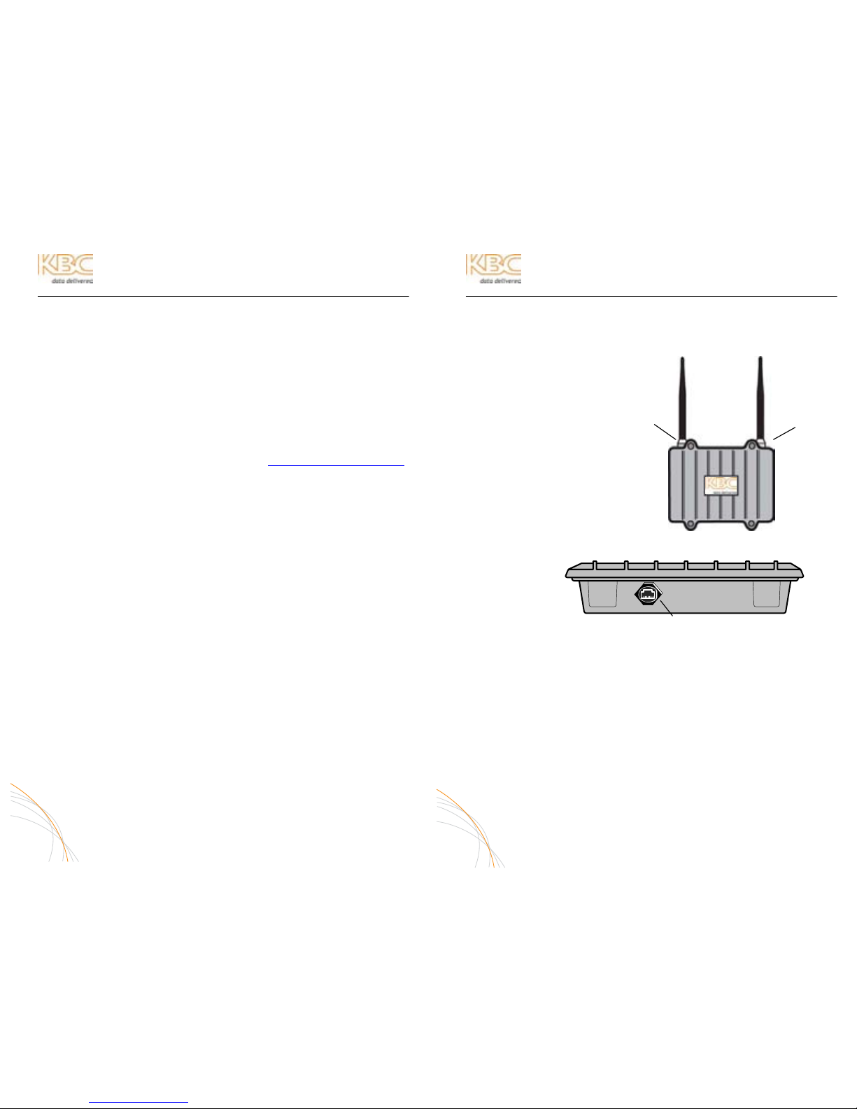
WIRELESS ETHERNET MESH NODE DETAILS
OUTDOOR DUAL RADIO NODE (MESH-AA-Ox, MESH-BA-Ox)
A. FRONT VIEW
1. Primary Antenna Port
2. Secondary Antenna Port
1. Ethernet Port (RJ-45)
4
B. BOTTOM VIEW
1
2
Note 1: supplied omni-directional
antennas shown. Higher gain directional
antennas are available as upgrade
options. Patch, yagi and parabolic
antennas connect using an N(m)-to-N(m)
1 meter connecting cable which is
included in antenna upgrade part
numbers.
1
1
Note 2: Outdoor
weatherproof tape
recommended over
antenna port and
antenna connection
at N-connector
Note 3: Seal using LAN port weatherproof strain relief
assembly provided in the node kit. If cabling exposed
to the elements, use only outdoor rated cables.

WES Mesh Wireless System Operations Manual
WIRELESS ETHERNET MESH NODE DETAILS (CONTINUED)
OUTDOOR SINGLE RADIO NODE (MESH-A-Ox & MESH-B-Ox)
POWER INJECTION MODULE (PIM)
Note: The Power Injector Modules are not weatherproof units and must be protected from moisture.
PIM DESCRIPTION
A. FRONT VIEW
PoE NOTIFICATION
The Mesh nodes are mid-span compliant and must be powered using
the supplied power injection module. If an 802.3af compliant PoE switch
is used, connect to a non-PoE port of the switch only.
5
WES Mesh Wireless System Operations Manual
MESH CONNECTION DIAGRAM
The following wiring schemes represent the configuration that has been tested and
verified by KBC based on typical Ethernet wiring solutions. Other wiring config urations
could be possible based on the application. A bench test is recommended to verify the
design below.
CONNECTING TO AN IP CAMERA
CONNECTING TO A KBC ENCODER OR DECODER
CONNECTING TO AN ETHERNET 10/100/1000 SWITCH
* Type of Ethernet cable is determined by the Ethernet device LAN
port. If the LAN port is a 10/100 port then the cable will be a crossover
cable. If the port is a gigabit connection then a straight-through cable
would be used. KBC recommends that both types of cables are on
hand in case your particular device requires a different configuration
than what KBC has tested.
6
A. FRONT VIEW
1
1. Ethernet Port (not shown)
Seal with strain relief and
use outdoor rated cable
2. Antenna Port
B. BOTTOM VIEW
1
2
1
2
3
1. DATA IN – Connect to Ethernet Device
2. POWER LED – Indicates power is o n when lit
3. P+DATA OUT – Connect to Mesh Node
1 3
2
Ethernet Cat5*
Straightthrough
Crossover cable
Data
In
P+Data
Out
12 VDC
PS
Straightthrough
Data
In
P+Data
Out
12 VDC
PS
12 VDC
PS
Straightthrough
Ethernet Cat5*
Data
In
P+Data
Out
Note: Outdoor weatherproof tape
recommended over antenna port and
antenna connection at N-connector
1. Ethernet Port (not shown)
Seal with strain relief and
use outdoor rated cable
2. Antenna Port

WES Mesh Wireless System Operations Manual
MESH TOPOLOGY DESIGN
A true mesh topology is set up when a node can associate and communicate with at
least two other mesh nodes. However, for ideal mesh operability, keep design in the
topology to the extent that no more than two nodes come into any one radio. In
essence, the mesh topology would appear in triangles of communication so that
redundant paths are still established.
Example of triangle mesh
communication:
To add more nodes to the mesh network, the topology would be built as shown:
(For an understanding of WiFi-0, WiFi-1, mode and channel see page 18)
Remote Node 2
Remote Node 3
Remote Node 1
Remote Node 5
Head End Node
Remote Node 4
Frequencies and antenna gain options are shown for illustration purpose only. A site
survey is the optimal way to determine frequency se lection in a given environ ment. A
frequency can be also be selected using the RSSI and rate figures as descr ibed on
page 12 of this manual. In some environments additional nodes may be necessary to
reduce the number of hops while enabling redundant paths.
7
WES Mesh Wireless System Operations Manual
NODE INSTALLATION & OPERATION
A. PERFORM COMMAND PROMPT TEST
1. Connect the Mesh nodes to a laptop as sho w n in the following
diagram (default settings for node 1 & 2 shown):
IP: 192.168.1.x IP: 192.168.1.11 IP: 192.168.1.10 IP: 192.168.1.x
ID: 02 ID: 01
WiFi-0: 11g, 1 WiFi-0: 11g, 1
WiFi-1: 11a, 36 WiFi-1: 11a, 36
2. Open Command Prompt from the Start Menu/Programs/Accessories
3. Allow approximately 45 seconds, then ping the IP addresses shown on
the configuration table included in the shipment.
a. Ping the connected node (ping 192.168.1.10)
b. Ping the wireless node (ping 192.168.1.11)
c. Ping the camera/encoder (ping 192.168.1.xxx)
d. Open a web browser and access the camera interface
8
WiFi-0:
11
a 36
WiFi-1: 11a 165
WiFi-0:
11a 165
WiFi-1:
11g 6
WiFi-0:
11g 6
WiFi-0:
11
a 36
WiFi-1:
11
a 15
7
WiFi-0:
11
a 15
7
WiFi-1:
11a 165
WiFi-0:
11g 6
WiFi-1:
11a 60
WiFi-1:
11a 60
Note:

WES Mesh Wireless System Operations Manual
NODE INSTALLATION & OPERATION (CONTINUED)
A. MOUNT MESH NODE
Attach the pole mount to the Mesh node case using the hardware kit.
B. CONFIGURE CABLE
Determine the length of Cat5 cable that w ill be needed a nd where the PI M will
be located. The total cable length from the radio to the Ethernet device cannot
exceed 100 meters, however, the PIM can be located anywhere along the 100
meters of cable. The PIM and power supply are not weather proof and must
be placed indoors or in an environmental enclosure. On the Mesh node end,
feed the CAT5 cable through the supplied assembled weatherproof connector
kit. Crimp an RJ45 CAT5 connector on the end of th e cable and configure as a
straight-through patch cable.
C. CONNECT MESH NODES
Connect the cable to the Ethernet Port on the node. S lide the cable jacket up
to the base of the connector. Slide the weatherproof connector over the cable
jacket and screw it into the node and tighten. Tighten the clamping nut until
the Cat5 cable is sealed in the connector.
D. ESTABLISH LINK
Follow above steps, A through E, for all nodes of the system to be established.
E. VERIFY CONNECTION
Connect the first node to a laptop and open Command Prompt once again. The
node LAN port should be accessible at https://192.168.1.10. At this point, the
second node should be accessible at https://192.168.1.11 unless otherwise
noted. The subsequent nodes should be accessible at https://192.168.1.12;
1.13; 1.14, etc upon connection. Refer to the provided Configuration Table for valid IP
Addresses.
NOTE: In some cases, depending on the physical and RF environment, a
useable throughput rate may not be possible. Contact KBC for more
information – 888-366-4276 or info@kbcnetworks.com.
9
WES Mesh Wireless System Operations Manual
ADVANCED OPERATION
WEB BROWSER INTERFACE
Each Mesh node has a web browser interface to access the advanced setup functions.
If changing advanced settings, be sure to connect and power the radios individually.
To access this interface, connect the node to the Ethernet port on a computer, lau nch
the web browser and type in the default IP address at https://192.168.1.10. Please
note that the “s” must be included as the IP alone or along with http:// will not
access the interface. The configuration of the compu ter used to access the node may
need to be changed depending on its IP settings. The IP address of the computer
should be set to 192.168.1.xxx. The xxx setting can be any address 2 – 254
excluding 10 or any other IP address(s) you wish to use for a node on that subnet (or
Encoder/Decoder/WES product if applicable). The Subnet mask should be
255.255.255.0. If you have any questions or concerns about changing these
settings, please contact your network administrator.
Note: The GUI interface is only accessible via a secure web browser address
(i.e, https://192.168.1.10
)
ACCEPTING THE WEB BROWSER SECURITY CERTIFICATE
In order to reach the ID/password log in, the web browser must en sure its security.
The browser will believe that the connection is not safe but it is OK to accept the
certificate and access the interface.
Mozilla Firefox (Recommended Browser) Users:
1. Click “I Understand the Risks”
2. Click “Add Exception”
3. Click “Confirm Exception”
MS Internet Explorer Users:
1. Click “Continue to this
Website”
2. Enter ID and password at
prompt
10
1
2
3
1

WES Mesh Wireless System Operations Manual
ADVANCED OPERATION (CONTINUED)
WEB BROWSER LOG IN
The default ID and password for the Mesh node is admin
and admin
.
WARNING
: IF YOU CHANGE THE USER NAME AND/OR
PASSWORD, YOU WILL NEED TO KEEP A RECORD OF
YOUR CHANGES IN A SAFE PLACE. IF THE PASSWORD IS
FORGOTTEN OR MISPLACED, THE UNIT MUST BE
RETURNED TO KBC TO BE RESET.
INTERFACE CONFIGURATOR WEB PAGES
A. DIAGNOSTICS
1. Monitor
The throughput monitor graph will show the amount of throughput traffic
that is being transmitted across the Mesh system. The rate can be seen
in Megabits per second or percentage of overall throughput capacity.
The graph shown indicates a 2.5 Mbps stream
being pulled across the Mesh network. As soon
as the stream is accessed, the graph jumps
from <1M up to an average of 2.41 Mbps.
2. Network
Below is a screen shot of the network diagnostic tools. See following
pages for detailed information.
11
WES Mesh Wireless System Operations Manual
ADVANCED OPERATION (CONTINUED)
NETWORK TOOLS
In addition to using the Microsoft® Command Prompt, the user can also use the
Mesh web browser to ping the other Mesh nodes on the connected networ k(s).
NETWORK INFORMATION
Mesh routes, stations and the network topology can be identified through the
network information diagnostic tools.
SYSTEM ROUTES
The routes indicate the wireless network topology of the mesh connections.
MESH STATIONS
The Mesh stations show the throughput rate and signal strength (RSSI). These
indicators help to determine what environmental factors could be limiting the
mesh connections. The RSSI can be used as an in depth form of antenna
alignment for high gain directional antennas.
A max connection is 54 M for the rate. Signal strengths can be any number 0-100
but typically seen in the 30 to 40 range. Any RSSI above 20 is an acceptable link.
The rate and RSSI indications are a snapshot of the last packet to cross the link. All
rate and RSSI figures should be refreshed several times to achieve an average
number.
12
User name: admin
Password: admin

WES Mesh Wireless System Operations Manual
ADVANCED OPERATION (CONTINUED)
MESH ROUTES
The following mesh route was taken from a point-to-point example. Typical mesh
routes will show at least three MAC addresses. The first line is the connected
mesh node and the second line is the remote node.
SITE SURVEY / ANTENNA ALIGNMENT
These tools assist in finding the ideal frequency to use as well as aiming
directional antennas.
ANTENNA ALIGNMENT (WiFi-0 / WiFi-1 ALIGN)
The antenna alignment tool is intended for directional antennas and looks at the
overall frequency. It is important to operate the mesh nodes in a point-to-point
method (i.e, turn off all other nodes on that particular frequency) in order to get a
correct reading while aligning directional antennas. To align an antenna connected
to the primary port, click ALIGN next to WiFi-0. WiFi-1 refers to the secondary
port. The browser will continuously refresh with updated signal strength indicators
upon each refresh.
The bar will change color with reference to the signal strength.
Adjust the antenna slightly to see the change on the color-coded bar
on the tool. The low, weak signals are red and orange, etc. while the
strong connections are green and blue colors.
13
WES Mesh Wireless System Operations Manual
ADVANCED OPERATION (CONTINUED)
SITE SURVEY (SCAN)
To scan for available access points in the environment, one radio must be
disabled. Upon disabling, that particular radio can perform a site analysis of nonproprietary and non-hidden SSIDs for 802.11a, b and g access points.
1. System
The opening page of the internal configuration web browser displays the
default settings. All configuration changes will be seen on this page as
well.
a. System Information
System Name: This can be any identifier which is designated on the
host name on the Set Up page.
OS Version: This is the software version and Serial BOD put
together. The Serial BOD can also be found on the Firmware page.
System ID: The individual identification number for the mesh node.
Node ID: See the Set Up page for the mesh ID system.
b. Status Information
Memory Used: This is the system load, the percentage will fluctuate.
System Uptime: Time since last system reboot.
Wireless Mode: Mesh or Mesh/AP depending on setting. See Set Up
page.
Routing Mode: Normal, Gateway or Advanced. See Set Up page.
14

WES Mesh Wireless System Operations Manual
ADVANCED OPERATION (CONTINUED)
c. WiFi-0 Interface
Media Type: IEEE 802.11 Wireless Ethernet
MAC Address: Each radio has an individual MAC address. Note this number
for tracking purpose when looking at RSSI figures. See
RSSI notes on Mesh Stations page.
Status: If enabled and connected, the status will be “Running”. If
the radio is disabled or not connected to another node, the
status will be “Not Associated.”
Mode: Shows the selected mode for the WiFi-0 radio. See Set Up
page.
Channel: Shows the selected channel for the WiFi-0 radio. See Set Up
page.
Power: Shows the selected power output for the WiFi-0 radio. See
Set Up page.
Rate & RSSI: Snapshot of the connection rate and signal strength
Noise Floor:
Inbound Packets and Error Information: Indicates the packet transfer
between wireless radios.
Outbound Packets and Error Information: Indicates the packet
transfer between hard connected devices.
15
WES Mesh Wireless System Operations Manual
ADVANCED OPERATION (CONTINUED)
d. WiFi-1 Interface
The same configurations as described under the WiFi-0 Interface are
shown for the secondary radio on the WiFi-1 Interface. If the product
is a single-radio node, the WiFi-1 Interface will not appear.
e. Net-0 Interface
The Net-0 Interface refers to the LAN connection.
16

WES Mesh Wireless System Operations Manual
ADVANCED OPERATION (CONTINUED)
B. NETWORK
1. Set Up
a. System Configuration
Host Name: The mesh node can be named any Host Name for
identification purpose.
Node ID: Each mesh node must be set to a separate node ID (01 –
99) to avoid conflict. This ID is one factor that determines the WAN IP
so that all the user must keep track of are LAN IP addresses.
Wireless: Mesh format is the default wireless mode. Mesh/AP mode is
available to enable the WiFi-1 secondary radio as an Access Point.
Access Point Mode: Enables the secondary radio to have
it’s own SSID and Password. A laptop WiFi subscriber unit
must be WPA2 compliant to access the AP. AP access
grants access to the entire mesh network.
Routing: Normal is default. Gateway is used when a node is
connected to a router to provide access to an exterior network, such
as the internet. Advanced routing is used to set up static routes in
order to connect to other subnets.
Gateway Example: (Connecting node 192.168.1.10 to an external
network routed through a 192.168.1.1 router)
Advanced Routing Example:
In the above advanced routing example, the 192.168.3 subnet can be found by routing
through the 192.168.1.11 node because 1.11 is communicating with a node
addressed on the 3.x subnet. Since this interface belongs to the 192.168.1.10
node, the 1.11 node must be accessible through a switch. Other routes can be
added and the gateway route can also be listed under the “Default Route.”
17
WES Mesh Wireless System Operations Manual
ADVANCED OPERATION (CONTINUED)
b. Mesh Configuration
i. WiFi-0 Configuration – Primary Radio
SSID & Password: The default “kbc-mesh” and “pskpskpsk” can be
changed, however, each mesh node must be set to the same SSID
and password.
Mode: 11a, b, and g are standard WiFi-0 wireless options on part
numbers MESH-AA-Ox & MESH-A-Ox and WiFi-1 options on 900
MHz mesh dual radio nodes. 900 MHz is available on part numbers
MESH-BA-Ox & MESH-B-Ox only. 900 MHz appears as 11g mode.
“Turbo a” is also available for added throughput, however,
reduced number of channel options. 802.11b and g are 2.4 GHz
while a and Turbo a are 5 GHz.
Channel: Based on the mode selection, the various channels are
shown. All 802.11g & 11a Turbo channel selections appearing in
orange indicate a non-overlapping channel. All regular 802.11a
channels are non-overlapping so they all appear in white rather
than orange. Upon selecting the desired channel, the frequency
will be shown in Megahertz (Mhz) along with the power output in
dBm. If the power output is adjusted, the dBm rating will adjust in
accordance.
Power: The radio power output can be altered by percentage
MAC Filter: The node can filter MAC addresses and allow particular MAC addresses
when enabled.
18

WES Mesh Wireless System Operations Manual
ADVANCED OPERATION (CONTINUED)
ii. WiFi-1 Configuration – Secondary Radio
The channel settings for WiFi-1 cannot be the same as WiFi-0.
However, the mode, power and MAC Filtering can be the same.
Between two different nodes, it is possible to have one WiFi-0
configuration match the WiFi-1 of the other node. In essence,
WiFi-0 of one node can talk to WiFi-1 of another provided the
mode and channel selection matches.
c. LAN Configuration
IP Address: The node can be set to any allowable IP address provided
it does not conflict with another IP on the network. See gateway and
advanced routing if connecting to a router for an exterior network.
The default setting for the Mesh nodes begin at 192.168.1.10 and
increase by single digits on their 4
th
octet. The nodes are not required
to be configured to any particular arrangement as long as there are
no duplicated IP addresses on any one network.
Netmask: This is the subnet filter. Default setting is 255.255.255.0
Media/Speed: Default set to auto-negotiate. If connecting to a switch
or router, the media speed might need to be changed to full or half
duplex and 10 or 100 Mbps.
C. SYSTEM
The software version, serial BOD, country code, default restore and password
settings are indicated/configured through the System links.
1. Firmware
KBC recommends restoring the defaults prior to firmware updates,
however, the previous settings will remain if not restored.
Select the “Country / Region” & “Regulatory Domain” to use the nodes under t he
allowable parameters in each country or region. This setting will enable only the
frequencies available by each specific nation’s communications governing
organization. Default is US/Canada (FCC / IC)
SW Version & BOD Serial: Indicates firmware version
19
WES Mesh Wireless System Operations Manual
ADVANCED OPERATION (CONTINUED)
a. Restore Defa ults
The following configurations will appear on the Set Up page upon
restoring to default:
Host Name: kbc
Node ID: 01
Wireless: MESH
Routing: NORMAL
Mesh SSID: kbc-mesh
Password: PSKPSKPSK (note: this is all capitalized)
WiFi-0 Mode: 11g
WiFi-0 Chan: 1
Power: 100%
MAC Filter: DISABLED
WiFi-1 Mode: 11a
WiFi-1 Chan: 36
Power: 100%
MAC Filter: DISABLED
IP Address: 192.168.1.10
Netmask: 255.255.255.0
Media/Speed: AUTOSELECT
2. Password
To change, enter the new password and confirm. When you select another
link, such as Set Up for example, you will need to re-enter the new
Username and password.
ANY CHANGES TO THE USERNAME AND/OR PASSWORD MUST BE SAVED
AND KEPT AVAILABLE. IN THE EVENT AN ID OR PASSWORD IS
FORGOTTEN, THE NODE MUST BE RETURNED TO KBC FOR A HARD
RESET. ALL CONFIGURATIONS WILL BE LOST AND RETURNED TO
DEFAULT SETTINGS UNLESS OTHERWISE NOTED.
3. Reboot
The Reboot link will soft restart the device. Any configuration change that
was saved will be held after the reboot. Settings changed without applying
(clicking save) will not be held after the reboot.
20

WES Mesh Wireless System Operations Manual
MESH CONFIGURATION TABLE
KBC recommends that a spreadsheet of the mesh system be kept on hand for
reference. A worksheet providing all of the default settings is included in the shipment.
These settings along with any changes should be kept and tracked in a format similar to
the example provided below:
S/N ID Host Name Mode IP WiFi-0 WiFi-1
03716 10 Head End Mesh 192.168.1.10 11a; 36 11a; 60
03717 11 PTZ Cam Mesh 192.168.1.11 11a; 60 11a; 165
03718 12 Lot A Mesh 192.168.1.12 11a; 36 N/A
03719 13 Park Mesh/AP 192.168.1.13 11a; 165 11g, 11
03720 14 Lot B Mesh 192.168.1.14 11a; 165 N/A
Other notes and settings can be important to record in the spreadsheet. The above
example shows various types of KBC Mesh nodes implemented into a system. The “not
applicable” notations under the WiFi-1 indicate that those two nodes are single-radio
and do not have a WiFi-1 setting. Node # 13 set as Mesh/AP mode is to show a node
set to AP mode for the secondary radio. The SSID and Password set for that AP should
also be included in the spreadsheet.
21
WES Mesh Wireless System Operations Manual
MESH PRODUCT SPECIFICATIONS
For product improvement, design and specifications are subject to change withou t notice.
RF MODULES
RADIO SPECIFICATION
Transmitting Frequency (Selectable by Country within GUI Interface)
USA: 2.400 – 2.483GHz, 5.15 ~ 5.35 GHz, 5.725 ~ 5.825 GHz
Europe: 2.400 – 2.483GHz, 5.15~ 5.35 GHz, 5.47 ~ 5.725 GHz
Japan: 2.400 – 2.483GHz, 4.90 – 5.091GHz, 5.15 – 5.25GHz
China: 2.400 – 2.483GHz, 5.725 ~ 5.85 GHz
Channel Capacity 802.11b/g
US/Canada: 11 (1 ~ 11)
Major European Countries: 13 (1 ~ 13)
France: 4 (10 ~ 13)
Japan: 11b: 14 (1~13 or 14th), 11g: 13 (1 ~ 13)
China: 13 (1 ~ 13)
Non-overlapping Channels 802.11a
US/Canada – 12: (5.15 ~ 5.35GHz, 5.725 ~ 5.825GHz)
Europe - 19: (5.15 ~ 5.35GHz, 5.47 ~ 5.725GHz)
Japan – 4: (5.15 ~ 5.25GHz)
China – 5: (5.725 ~ 5.85GHz)
Modulation
802.11b/g: DSSS (DBPSK, DQPSK, CCK) / OFDM (BPSK, QPSK, 16-QAM,
64-QAM)
802.11a: OFDM (BPSK, QPSK, 16-QAM, 64-QAM)
Modulation Speed
802.11b/g: 11, 5.5, 2, 1 Mbps, auto-fallback,
802.11g: up to 54 Mbps
802.11g: (Super mode): up to 108 Mbps
802.11a: (Normal mode): 54, 48, 36, 24, 18, 12, 9, 6Mbps, autofallback
802.11a: (Turbo mode): 108, 96,72,48,36,24,18,12 Mbps, autofallback
TX Power
802.11b: 18dBm
802.11g: 18dBm @6Mbp, 15dBm @54Mbps
802.11a: 17dBm @6Mbps, 13dBm @54Mbps
22

WES Mesh Wireless System Operations Manual
MESH PRODUCT SPECIFICATIONS
For product improvement, design and specifications are subject to change without notice.
RF MODULES (CONTINUED)
Receive Sensitivity
802.11a: -88dB@6Mbps, -87dB@9Mbps, -85@12Mbps,
-83dB@18Mbps, -80dB@24Mbps,-75dB@36Mbps,
-73dB@48Mbps, -71dB@54Mbps
802.11b: -95dB@1Mbps, -94dB@2Mbps, -92dB@5.5Mbps,
-90dB@11Mbps
802.11g: -90dB@6Mbps, -89dB@9Mbps, -87@12Mbps,
-85dB@18Mbps, -82dB@24Mbps,-79dB@54Mbps
Antenna Connectors: 2x N-Type Female
NETWORK MANAGEMENT
Interface: Web GUI via https secure
Protocols Used: All TCP/IP
Multicast Support: Yes
Quality of Service: 802.11e (WME), ToS, QoS
SECURITY
Routing, VPN, Encryption Support (802.1x, AES-CCM, TKIP, WEP, WPA, WPA2)
MECHANICAL
Physical Dimensions: 7.125”H x 8.375”W x 2.188”D
Weight: 3.2 lbs
Environmental: NEMA-67, IP65
Enclosure Material: Die-Cast Aluminum
Mounting Hardware: Pole Bracket and U-bolts
POWER
Power Requirements: 7VDC – 20VDC
Power Method: Power-over-Ethernet (PoE) via power injector module (“mid-
span” compliant – pins 4,5 positive – pins 7,8 ground)
Connector: RJ45 – in and out of power injection module
Cable Specifications: 100 Meters (328 Feet) on 24 AWG CAT-5 cable
ENVIRONMENTAL
Operating Temperature: -40C to +80C
Humidity: 95% non-condensing
APPROVALS
FCC ID:
Standard: NKRDCMA82 900: SWX-XR9
IC:
Standard: 4441A-DCMA82 900:
CE:
Standard: (TBD) 900: (TBD)
23
WES Mesh Wireless System Operations Manual
MESH PRODUCT SPECIFICATIONS
For product improvement, design and specifications are subject to change withou t notice.
POWER INJECTION MODULE (PIM)
MECHANICAL
Physical: Plastic housing, not weatherproof
Dimensions: 1.0”H x 2.125”W x 1.625”D
Weight: 1.1oz
POWER
Power Requirements: 12 VDC 1A (wall transformer supplied)
Power-over-Ethernet (PoE): PoE “mid-span” compliant
(pins 4,5 positive – pins 7,8 ground)
Connectors: DC Jack 2.5 mm x 5.5 mm
center positive, 2 – RJ45
Warranty
2 YEAR LIMITED WARRANTY (SEE PAGE 26 FOR DETAILS)
24

WES Mesh Wireless System Operations Manual
TROUBLE-SHOOTING
Problem Suggestion
IP address of the
directly connected
node will not reply
to ping response
- Verify correct static subnet setting on connected laptop/PC
- Verify correct type of cable needed between laptop/PC and
“Data In” of the PIM. Crossover cable may be necessary if the
LAN port of the computer is 10/100. If gigabit connection then
straight-through should be used.
- Verify power to the PIM
Problem Suggestion
IP address of the
wirelessly
connected node will
not reply to ping
response
- Verify correct static subnet setting on connected laptop/PC
- Verify gateway setting of the laptop/PC matches the LAN IP o f
the directly connected Mesh node.
- Verify a ping reply from the directly connected node
- Ping the node from the GUI interface of the cable connected
node.
- Verify correct type of cable needed between laptop/PC and
“Data In” of the PIM. Crossover cable may be necessary if the
LAN port of the computer is 10/100. If gigabit connection then
straight-through should be used.
- Check advanced routing (page 17 of this manual)
- Check rate and RSSIs listed under “Mesh Stations” on the
Network page (see page 12)
- Verify power to the PIM
Problem Suggestion
No access to the
GUI via the
provided IP address
- IP address should be preceded by “https://” (i.e,
https://192.168.1.10
)
- Ping the IP using Command Prompt from your laptop/PC
Problem Suggestion
Video drops in and
out; recovers on its
own
- Weak signal strength (check rate and RSSI from “Mesh
Stations” on Network page in the Mesh GUI interface.
- Align directional antennas using the tool or RSSI figures
Problem Suggestion
Low RSSIs (signal
strengths)
- Try another frequency
- Make sure clear line-of-sight to intended radio
- If omni-directional antennas, try directional antennas.
- If directional antennas, align the antennas. Make sure
alignment is done in an “up/down” & “left-to-right” format in
very small increments. Align up or down until the strongest RSSI
(KBC recommends at least a 20 or above number for RSSI).
Then tighten the mounting. Then move left/right.
- Align using the alignment tool. Make sure other nodes are
turned off (except intended connected node)
Further assistance is available by contacting KBC at 888-366-4276 Monday-Friday 8am5pm Pacific Time for technical support. Or anytime via techsupport@kbcnetworks.com
E-mails are followed up before the end of the following regular business hours.
25
WES Mesh Wireless System Operations Manual
WARRANTY INFORMATION
KBC extends the following LIMITED WARRANTY to the original owner/purchaser of this
product as follows:
- Two years from the date of initial sale for all wireless and network products.
- Five years from the date of initial sale for all fiber products.
1) If, within the specified warranty period, this product, or any part or portion thereof,
shall prove upon examination by KBC, to be defective in materia l or workmanship,
KBC will repair or replace such part or portion at KBC’s option. The warranty
period on the repaired or replaced part or portion of this product shall be limited to
the unexpired term of the original warranty. The buyer shall be responsible for all
shipping and transportation of the product to KBC for any performance under this
warranty.
2) Conditions and Exceptions:
a) Any accident to this product, any misuse or abuse, alternation, use in modified
form, or any attempt to repair this product shall void this warranty. These
conditions to the warranty include, but are not limited to, incorrect power
connections, physical damage due to mechanical shock, exposure to moisture,
and circuit modification.
b) SHOULD THIS PRODUCT PROVE DEFECTIVE FOLLOWING PURCHASE, THE
BUYER, NOT THE MANUFACTURER, DISTRIBUTOR, OR RETAILER, ASSUMES
THE ENTIRE COST OF ALL SERVICING OR REPAIR, EXCEPT AS OTHERWISE
PROVIDED BY THE TERMS OF THIS WARRANTY.
c) FOR BREACH OF ANY WRITTEN OR IMPLIED WARRANTY ON THIS PRODUCT,
THE BUYER IS LIMITED TO THE FOLLOWING DAMAGES. (1) THE COST OF
LABOR TO REPAIR OR REPLACE DEFECTIVE PARTS OR PORTIONS OF THIS
PRODUCT, AND (2) THE COST OF THE REPAIRED OR REPLACE PARTS OR
PORTIONS OF THIS PRODUCT.
d) NO OTHER EXPRESSE D OR IMPLIED WARRANTIES HAVE BEE N MADE OR WILL
BE MADE ON BEHALF OF KBC WITH RESPECT TO THE SALE, REPAIR,
INSTALLATION, OPERATION, OR REPLACEMENT OF THIS PRODUCT. KBC
DISCLAIMS ANY IMPLIED WARRANTY OF MERCHANTABILITY OF THIS
PRODUCT OR ITS FITNESS FOR ANY PURPOSE, AND THE BUYE R AGR EES THAT
THIS PRODUCT IS SOLD “AS IS” AND THAT THE ENTIRE RISK OF QUALITY
AND PERFORMANCE OF THIS PRODUCT IS WITH THE BUYER, EXCEPT AS
OTHERWISE PROVIDED BY THE TERMS OF THIS WARRANTY.
e) Some states/jurisdictions do not allow exclusions or lim itations of incidental or
consequential damages, or limitations on how long an implied warranty lasts,
so the above exclusions or limitations may not apply to you.
f) If you do not wish to be bound by any of the provisions in this
warranty, please return the product(s) immediately.
3) Contact your dealer regarding return authorizations for out of
warranty repairs and any further product information.
26
WES Mesh Wireless System Operations Manual
APPENDIX
The appendix section is a two page additional segment of the manual that provides
information on antenna and mesh installation. KBC recommend s further education
and research than the WES Mesh Operations Manual can provide.
ANTENNA PROPAGATION
ANTENNA TYPES
Antennae can be polarized in a linear format or circular format. Since circular polarity
can pick up interference from both types of linear polarities, KBC uses linear polarized
antennae. Linear polarized antennae can be mounted in a vertical or horizontal
polarity. Refer to the antenna manufacturer’s specification sheet to identify the
antenna radiation pattern. The radiation pattern will identify how the antenna picks
up the signal. The below pictures are examples of the patch antenna (part number:
PAT5824) radiation patterns:
VERTI CAL POLARITY
PAT5824 radiation pattern in
vertical polarity for 2.4 & 5 GHz.
HORIZONTAL POLARITY
PAT5824 radiation pattern in
horizontal polarity for 2.4 & 5 GHz.
The circles on the left indicate the
radiation pattern for 2400 MHz
whereas the right side circles show
the various 5 GHz band
frequencies. Each color is a separate frequency.
Each type of antenna has a different radiation pattern. Those
patterns are available from the antenna manufacturer.
A-1
WES Mesh Wireless System Operations Manual
APPENDIX (CONTINUED)
A true mesh topology enables redundant paths. This can be done with frequency
configuration or by filtering MAC addresses. This se ction of the appendix shows the
mesh topologies by enabling the MAC filter within each node’s interface.
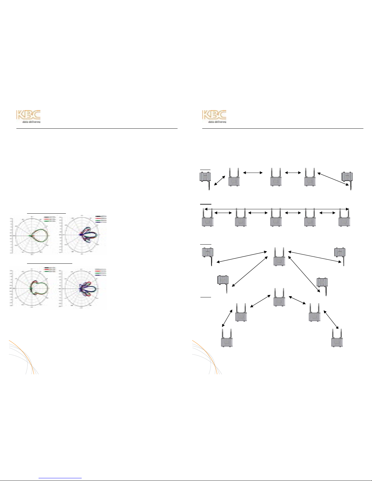
MESH TOPOLOGIES
LINE
N2 MAC N1 & N3 MACs N2 & N4 MACs N3 & N5 MACs N4 MAC
RING
N2 & N5 MACs N1 & N3 MACs N2 & N4 MACs N3 & N5 MACs N4 & N1 MACs
STAR
N3 MAC N1, N2, N4, N5 N3 MAC
MACs
N3 MAC N3 MAC
TREE
N2 & N3 MACs
N1 & N4 MACs N1 & N5 MACs
N2 MAC N3 MAC
MAC Filter in red text. The filter enable will cause the node to see one or two
other nodes. Restricting node association to one or two other nodes will
keep the radios from creating too many paths and hopping too frequently.
A-2
1
1
2
3 4
5
1 2 3 4
5
1
2
3
4
5
2 3
4 5

WES Mesh Wireless System Operations Manual
APPENDIX (CONTINUED)
MESH IP SCHEME
The mesh nodes are default configured to 192.168.1.10, 1.11, 1.12, etc. In streaming
CCTV applications, there are cameras attached to each of the nodes. It may be a
simpler set up to reconfigure the nodes so that each node is set on a multiple of 10 (i .e,
192.168.1.10, 192.168.1.20, 192.168.1.30, 192.168.1.40, etc.). Each connected
camera/video server could then be configured as follows: node- 192.168.1.20=
cameras- 192.168.1.21, 1.22, 1.23, etc. node- 192.168.1.30= cameras- 192.168.1.31,
1.32, 1.33, etc.
COMMAND PROMPT COMMANDS
During set up and/or trouble-shooting, KBC recommends using the Command Prompt
as the IP locating tool for the nodes. A regular ping will result in 4 replies. The following
commands are also useful:
Command Function
ping (IP Address) Response from Ethernet device at IP address
ping (IP Address) -t Constant response from Ethernet device at IP address
arp -d * Recommended command to flush the arp table
ipconfig Identifies the TCP/IP settings of the computer
ipconfig/flushdns Flushes DNS cache
GLOSSARY OF BASIC ETHERNET & WIRELESS TERMS
IP Internet Protocol
http / https hypertext transfer protocol (s= secure)
Packet Formatted data unit which is carried by a network connection
Frame The capsule in which the packet and link-layer info are transmitted
MAC Address A unique identification number for each Ethernet device
Subnet Distinctly addressed segment of a single IP network
IP Address Numerical identification assigned to devices operating on a TCP/IP
network
802.11 Set of standards for wireless local area network (WLAN)
communication on the 2.4 and 5 GHz bands (as pertaining to KBC
wireless products)
Frequency Band Range of frequencies typically identified by FCC/IC or other
communications governing agencies allotments
802.11b 2.4 frequencies (up to 11Mbps)
802.11g 2.4 frequencies (up to 54 Mbps)
802.11a 5 GHz frequencies (up to 54 Mbps)
802.11a Turbo 5 GHz frequencies that combine throughput from adjacent
frequencies in order to provide additional throughput
Fresnel Zone The three dimensional conceptualization of the antenna’s radiation
pattern
Line-of-Sight An open area high above all obstructions clear enough so as not to
impede upon the Fresnel zone
A-3
WES Mesh Wireless System Operations Manual
APPENDIX (CONTINUED)
TECHNICAL RECOMMENDATIONS – MESH INTEGRATION
The following section of the appendix will help to ensure long term weatherproofing of
the Mesh nodes.
LAN PORT WEATHERPROOF STRAIN RELIEF
Each mesh node kit includes a strain relief assembly kit that protects the LAN port and
RJ-45 connector on the underside of the node. Ensure that each node has its strain
relief connected to the LAN port.
WEATHERPROOF TAPE
Each antenna port should be further protected with tape around the N-connectors of
the antenna and antenna port on the node. Note- this tape is not provided.
CAT5 CABLES
All exterior cabling should be outdoor rated Cat5e or 6. All cables should be pulled
through conduit if otherwise exposed. Indoor rated Cat5 or 6 can get brittle or the
connectors can corrode over time.
FURTHER PROTECTION
Silicon sealing can trap moisture condensation on open ports to the node. Do not over
seal the LAN port. Keep silicon protection minimal (with strain relief connector) so that
moisture is able to release. Silicon should not be used in lieu of proper weatherproof
seals.
POWER OVER ETHERNET
The Mesh node is not 802.11af compliant and requires the PIM which injects 12 volts
DC. The PIM should be located in a place that can be reached easily (in case of need to
cycle its power), however, within a reasonable length of cable (~50 meters) to the
node to avoid voltage issues.
ACCESSIBILITY
The node should be mounted high enough to achieve clear line-of-sight to the next
node. It is recommended to place the PIM or switch at a location that is accessible
without the need of a lift truck or large ladder. All products should be kept from foreign
accessibility so that an attacker cannot interfere with the security products.
A-4
 Loading...