

KBC KBC-20VS Operator's Manual

MACHINERY
DlVlSION
6465
18
MlLE
ROAD
STERLlNG
HEIGHTS,
MI
4831
4
PHONE:
(586)
731
-3600
*
1
-8W-860-1740
FAX:
(586)
731
-7464
.
1
-800-862-1
740
MODEL
20"
VS
DRILL PRESS
THANK YOU FOR PURCHASING WlTH KBC MACHINERY. ALL KBC
MACHINES ARE BACKED BY OUR
1
YEAR PARTS REPLACEMENT
WARRANTY. WHEN USED AS INTENDED, AND WlTH PROPER
MAINTENANCE
THIS MACHINE WILL PROVIDE YOU WlTH YEARS OF
TROUBLE-FREE SERVICE. IF YOU NEED PARTS SIMPLY
FILL OUT
THE PARTS REQUEST FORM, AND FAX OR E-MAIL YOUR REQUEST.
ALL OTHER QUESTIONS PLEASE CONTACT US
@
:
KBC MACHINERY
6465 18
MILE ROAD
STERLING
HEIGHTS,MI
48314
PH
(800) 860-1740
FAX
(800) 662-1740
MACHINERY@KBCTOOLS.COM
-
WWW.KBCTOOLSANDMACHlNERY.COM
www.
KBCTOOLS
.
COM

PARTS REQUEST
FORM
YOUR COMPANY NAME:
STATE/PROVINCE
YOUR NAME
PHONE
#
+
EXT
FAX
#
MACHINE INFO:
MAKE/MANFACTURER
MODEL NUMBER
YEAR
MADE
PARTS REQUESTED:
PART#
DESCRIPTION
PLEASE INCLUDE COPY
(S) OF THE PARTS DRAWING EROM THE
MANUAL
AND CIRCLE THE PARTS NEEDED
FAX PARTS REQUEST TO (800)
862-2740
E-MAIL PARTS REQUEST TO:
machinery@kbc tools. corn
THANKS; KBC MACHINERY
-
MICHIGAN
VARIABLE SPEED
DRILLING
-
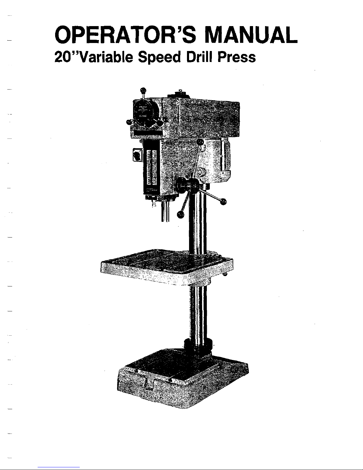
OPERATOR'S
MANUAL
2O"Variable
Speed
Drill Press
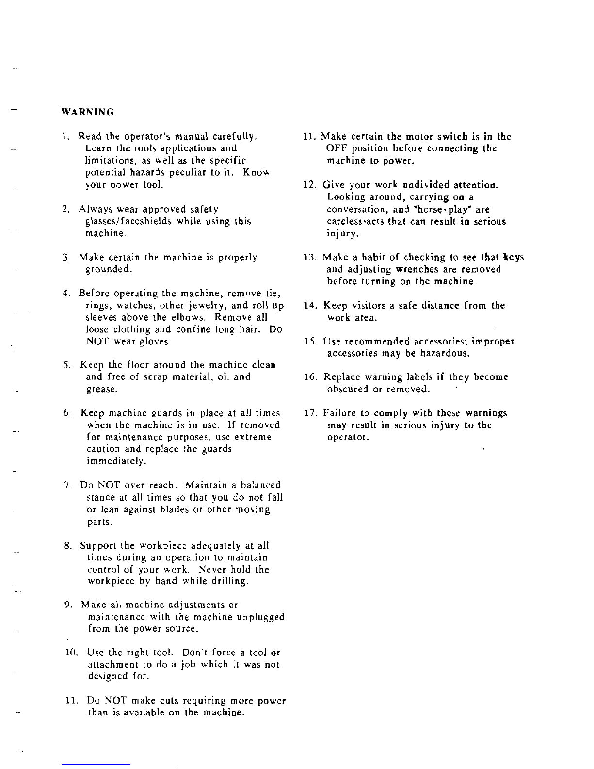
WARNING
1.
Read the operator's manual carefully.
Lcarn the tools applications and
limitations, as well as the specific
potential hazards peculiar to it. Knou
your power tool.
2.
Always wear approved safety
glasseslfaceshields while using this
machine.
3.
Make certain the machine is properly
grounded.
4. Before operating the machine, remove tie,
rings,
watchcs, other jeuelry, and roll up
sleeves above the elbows. Remove all
loose clothing and confine long hair. Do
NOT wear gloves.
5.
Keep the floor around the machine clean
and free of scrap material, oil and
grease.
6.
Keep machine guards in place at all times
when the machine is in use.
If removed
for maintenance purposes, use extreme
caution and replace the guards
immediately.
7.
Do
NOT
over reach. Maintain a balanced
stance at all times so that you do not fall
or
lcan against blades or other moving
parts.
8.
Support the workpiece adequately at all
limes during an operation to maintain
control of your work. Never hold the
workpiece
by
hand while drilling.
9.
Make all machine adjustments or
maintenance with the machine unplugged
from the power source.
10.
Ucc
the right tool. Don't force a tool or
attachment to do
a
job which it was not
designed for.
11.
Make certain the motor switch is in the
OFF position before connecting the
machine to power.
12.
Give your work undivided attention.
Looking around, carrying on a
conversation, and "horse-play' are
careless-acts that can result in serious
injury.
13.
Make a habit of checking to see that keys
and adjusting wrenches are removed
before turning on the machine.
14. Keep visitors a safe distance from the
work area.
15. Use recommended accessories; improper
accessories may he hazardous.
16.
Replace warning labels if they become
obscured or removed.
17. Failure to comply with these warnings
may result in serious injury to the
operator.
11.
Do NOT make cuts requiring more power
than is available on
the machine.
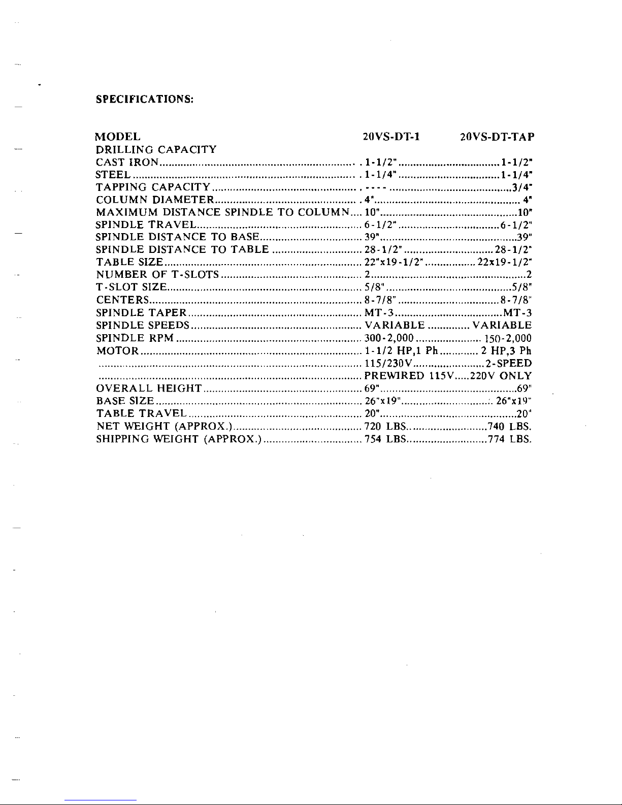
SPECIFICATIONS:
MODEL ZOVS-DT-1 2OVS-DT-TAP
DRILLING CAPACITY
CAST IRON
..................................................................
1-112"
..................................
1-112"
STEEL
...........................................................................
1- 114"
..................................
1- 114"
.....................................................
TAPPING CAPACITY
.........................................
314-
.................................................
...........
...............................
COLUMN DIAMETER
..
4"
4"
MAXIMUM DISTANCE SPINDLE TO COLUMN
....
10"
..............................................
10"
SPINDLE TRAVEL
.......................................................
6-112"
..................................
6-112"
SPINDLE DISTANCE TO BASE
................................
39"
..............................................
39"
SPINDLE DISTANCE TO TABLE
..............................
28-112"
..............................
28-112"
TABLE SIZE
..................................................................
22"x19-112"
.................
22x19-112'
NUMBER OF T-SLOTS
...............................
..
......
2
....................................................
2
T-SLOT SIZE
...............................................................
518"
.........................................
518"
CENTERS
.......................................................................
8-718"
..................................
8-718''
SPINDLE TAPER
..........................................................
MT-3
....................................
MT-3
SPINDLE SPEEDS
........................................................
VARIABLE
..............
VARIABLE
SPINDLE RPM
..............................................................
300.2,
000
......................
150.2, 000
MOTOR
..........................................................................
1-
112
HP, 1 Ph
.............
2
HP, 3 Ph
........................................................................................
1151230V
.......................
2-SPEED
.......................................................................................
PREWIRED
115V
.....
220V
ONLY
OVERALL HEIGHT
.....................................................
69"
..............................................
69"
BASE SlZE
...................................................................
26"x1gN
...............................
26"x111"
TABLE TRAVEL
.........................................................
20"
..............................................
20"
NET WEIGHT (APPROX.)
...........................................
720
LBS
...........................
740
LBS
.
SHIPPING WEIGHT (APPROX.)
.................................
754
LBS
...........................
774
LBS
.
CLEANING
After uncrating, remove protective coating from
all bright surfaces with a soft cloth moistened
with kerosene. Do
not
use acetone, gasoline or
lacquer thinner
-
these will damage painted
surfaces.
To prevent rust, wax the table with
paste wax.
INSTALLATION
The most accurate and vibration-free operation
will require the machine to be bolted to the
floor.
While this is not absolutely necessary, it
is highly recommended. The drill press should
be level and
rest solidly on the floor.
Place
shims under the three bolt holes to level the
drill press.
Equal pressure should be applied to
all three nuts when tightening to prevent
distorting the base.
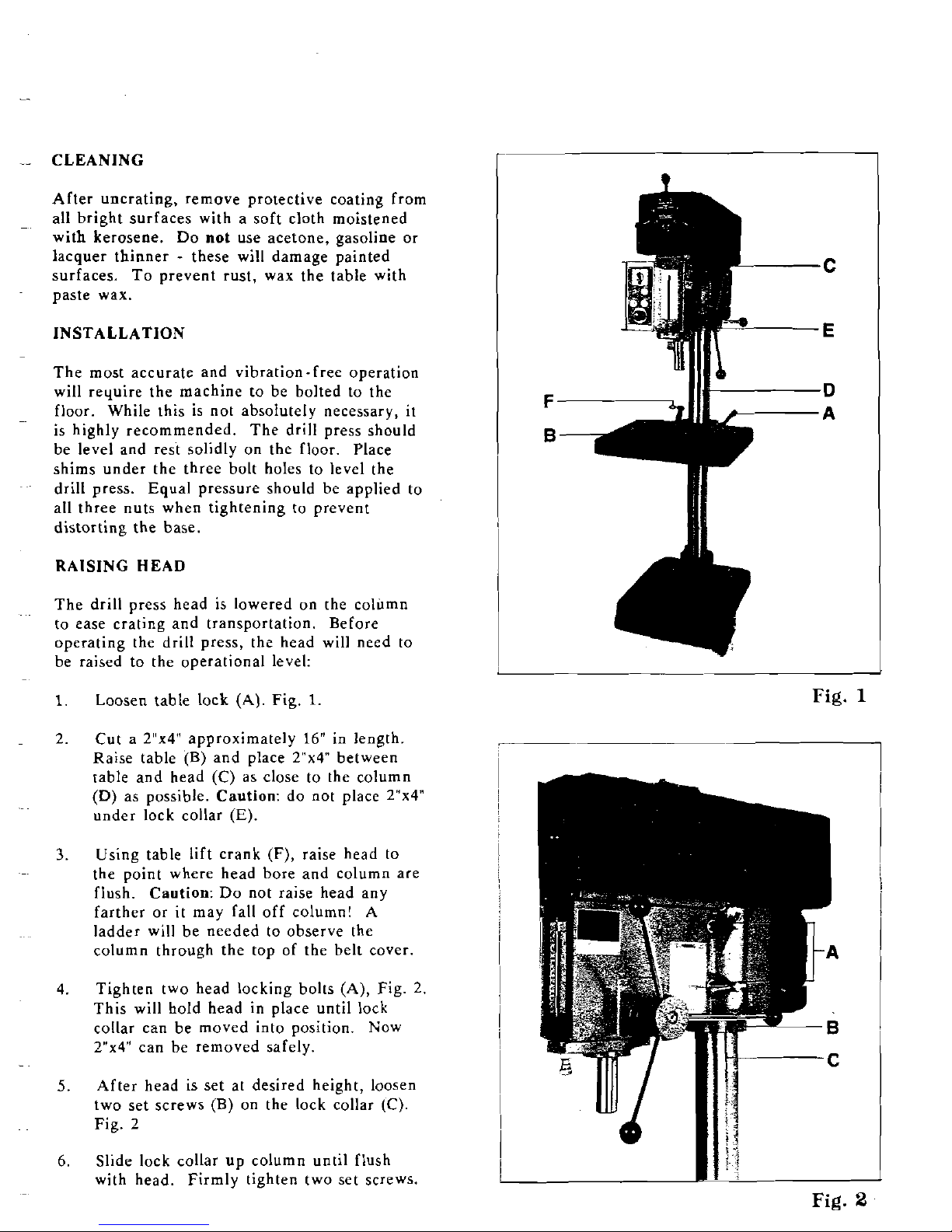
RAISING HEAD
The drill press head is lowered on the column
to ease crating and transportation.
Before
operating the drill press, the head will need to
be raised to the operational level:
1.
Loosen table lock
(A).
Fig.
1
2.
Cut a
2"x4" approximately
16"
in length.
Raise table (B) and place
2"x4 between
table and head
(C)
as close to the column
(D)
as possible. Caution: do not place Z"x4"
under lock collar
(E).
3.
Using table lift crank (F), raise head to
the point where head bore and column are
flush. Caution: Do not raise head any
farther or it may fall off column!
A
ladder will be needed to observe the
column through the top of the belt cover.
4.
Tighten two head locking bolts (A), Fig. 2.
This will hold head in place until lock
collar can be moved into position. Now
Z"x4" can be removed safely.
5.
After head is set at desired height, loosen
two set screws (B) on the lock collar
(C).
Fig. 2
6.
Slide lock collar up column until flush
with head.
Firmly tighten two set
scrcws.
1
Fig.
Fig.
 Loading...