


Ethernet Switch User Manual
Ethernet Switch
ESML6-P3
Management Software
User Manual

Ethernet Switch User Manual
TABLE OF CONTENTS
1 OVERVIEW ................................................................................. 3
1.1
I
NTRODUCTION
........................................................................................ 3
2 LOGGING IN................................................................................ 3
3 CONSOLE MANAGEMENT USING A WEB INTERFACE ................................ 5
3.1
3.1.1
M
AIN MENU
Device Status ....................................................................................... 6
............................................................................................ 5
3.1.1.1
3.1.1.2
3.1.1.3
3.1.1.4
3.1.2
3.1.2.1
3.1.2.2
3.1.2.3
3.1.2.4
3.1.2.5
3.1.2.6
3.1.3
3.1.3.1
3.1.3.2
3.1.3.3
3.1.3.4
Basic Info ...................................................................................... 6
Port Status ..................................................................................... 7
Port Statistics ................................................................................. 7
Device Operating Information ........................................................... 8
Basic Configurations .............................................................................. 8
IP Address ..................................................................................... 9
Device Information ......................................................................... 9
Port Configuration ......................................................................... 10
Change Password.......................................................................... 10
Software Update ........................................................................... 11
Upload & Download ....................................................................... 12
Advanced Configuration ....................................................................... 12
Port Rate ..................................................................................... 13
VLAN ........................................................................................... 13
Port Mirroring ............................................................................... 18
Link Check ................................................................................... 19
3.1.3.5
3.1.3.6
3.1.3.7
3.1.3.8
3.1.3.9
3.1.3.10
3.1.3.11
3.1.3.12
3.1.3.13
3.1.3.14
3.1.3.15
3.1.3.16
Manual_web_mgt_sw-ESML6-P3-Rev 1107
Copyright © KBC Networks Ltd. Page 1 of 51 www.kbcnetworks.com
Port Trunk ................................................................................... 20
Static FDB Multicast ..................................................................... 21
IGMP Snooping ............................................................................. 22
ARP ............................................................................................. 24
RSTP ........................................................................................... 24
RSTP Transparent Transmission ...................................................... 25
DT-Ring ....................................................................................... 26
QoS ............................................................................................ 32
Mac Aging Time ............................................................................ 34
SNTP ........................................................................................... 35
Alarm .......................................................................................... 36
SNMP .......................................................................................... 37

Ethernet Switch User Manual
3.1.3.17
3.1.3.18
3.1.3.19
3.1.3.20
3.1.4
3.1.4.1
3.1.4.2
RMON Configuration ...................................................................... 41
SSH ............................................................................................ 43
MOTD .......................................................................................... 45
AAA Configuration ......................................................................... 46
Device Management ............................................................................ 47
Save Configuration........................................................................ 48
Load Default ................................................................................ 49
Manual_web_mgt_sw-ESML6-P3-Rev 1107
Copyright © KBC Networks Ltd. Page 2 of 51 www.kbcnetworks.com
Ethernet Switch User Manual
1 Overview
1.1 Introduction
This manual covers the ESML6-P3 series management software. This software supports
Telnet, SNMP protocols and is compliant with networking regulations. This switch can be
managed and monitored using third party software. Configuration of the switch,
monitoring and other network management features can be achieved in 3 ways:
• via the console port (HyperTerminal)
• using Telnet
• using a web browser
2 Logging in
To access the switch via a web browser, the switch needs to be connected from one of its
RJ45 ports to the computer. The factory settings for logging are shown below. The user
can view or modify the IP address once in the management software.
IP address: 192.168.0.2
Subnet mask: 255.255.255.0
Default gateway: 192.168.0.1
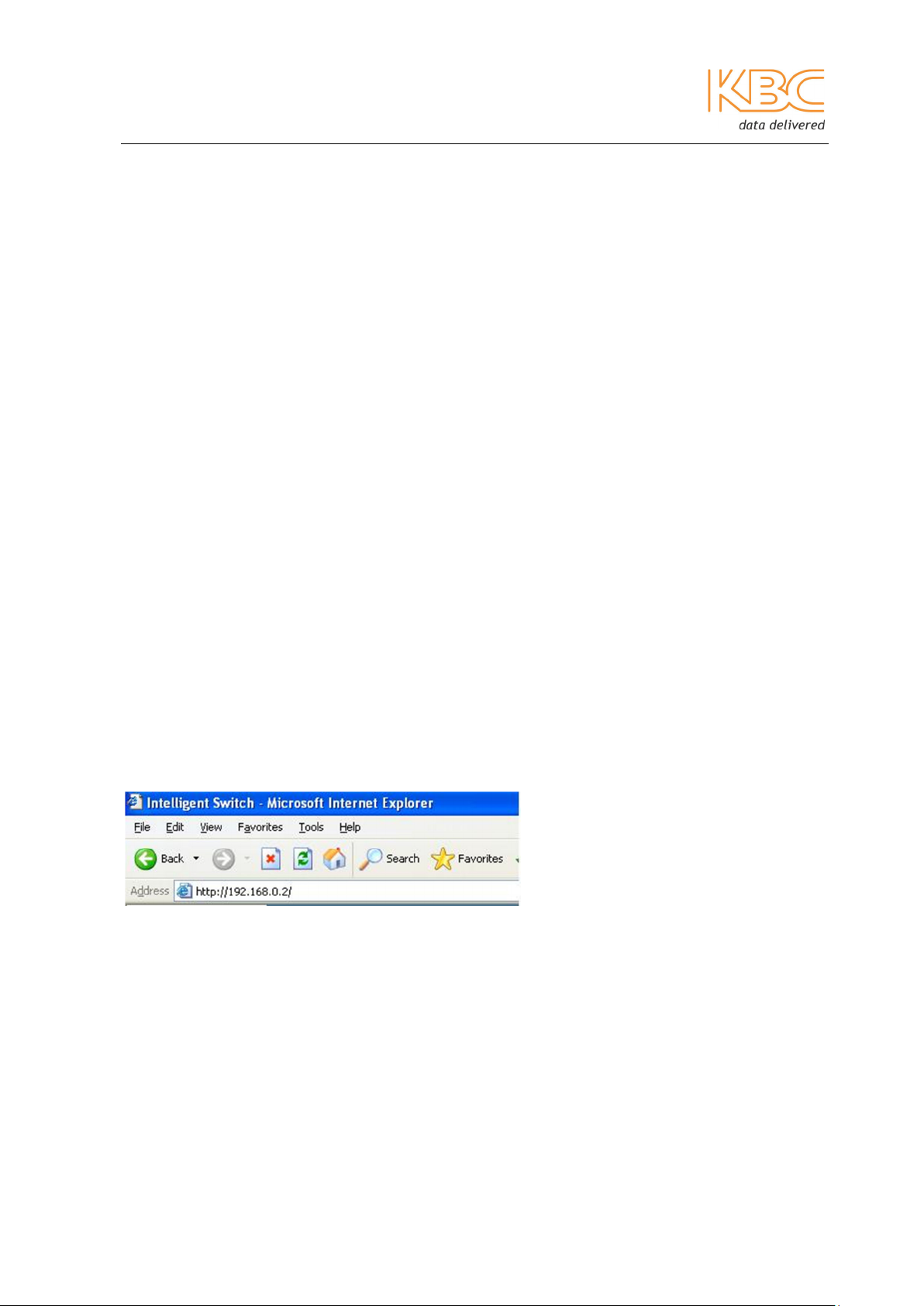
Access the web in the following way:
1. Start a web browser and enter the appropriate IP address, press the enter key to
open the connection as shown in Fig 2-1:
Fig 2-1 Start Web Management
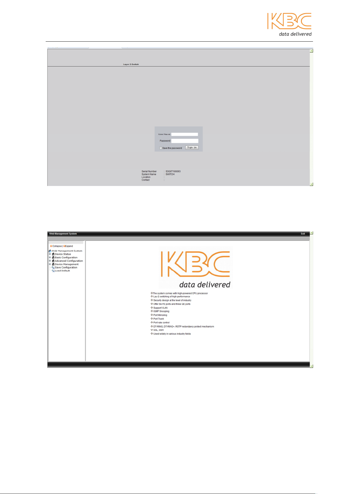
2. Enter the user name “admin” and password “123” in the presented page and
click on the “Log in” button.
Manual_web_mgt_sw-ESML6-P3-Rev 1107
Copyright © KBC Networks Ltd. Page 3 of 51 www.kbcnetworks.com
Ethernet Switch User Manual
Fig 2-2 Log in to Web Interface
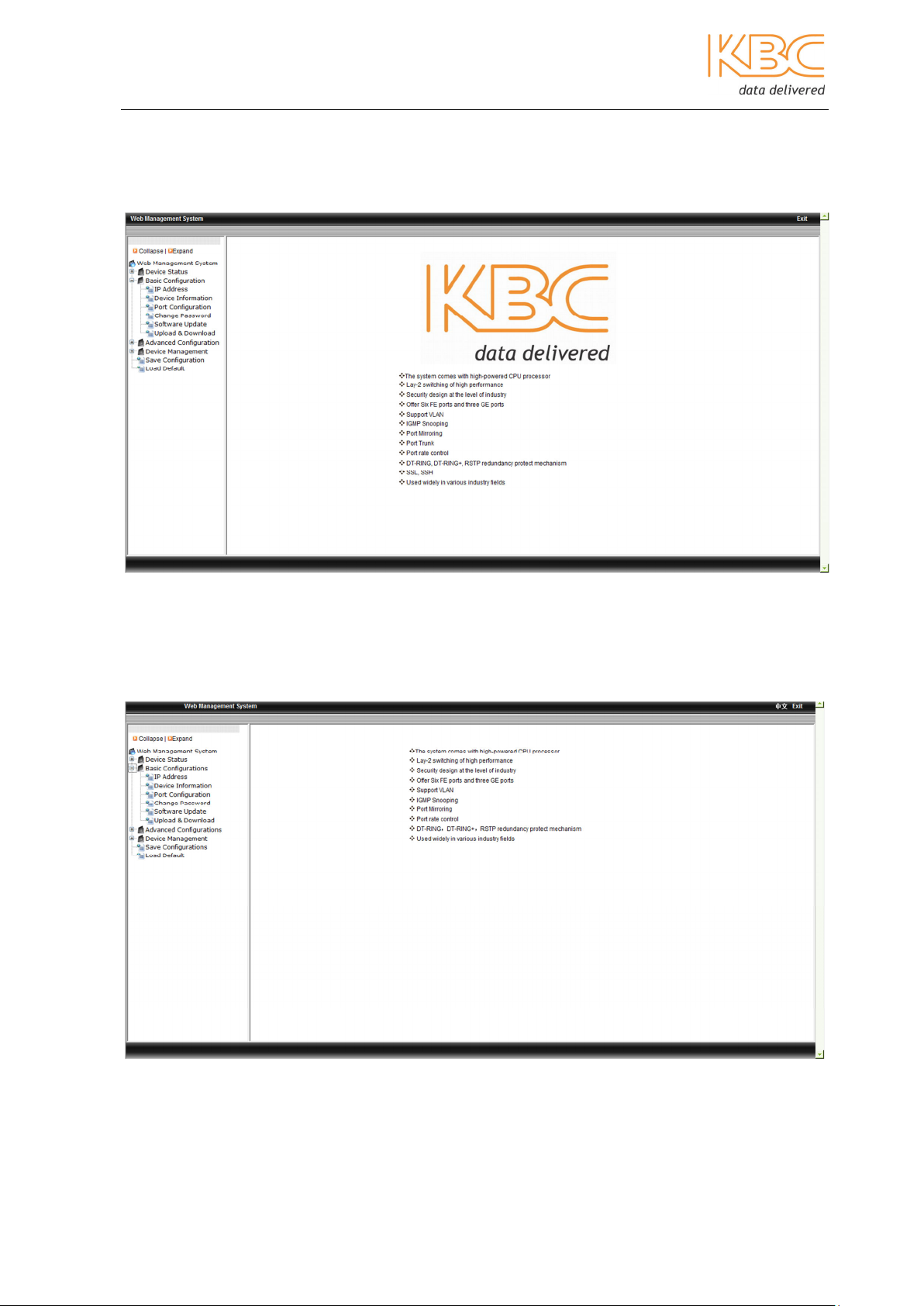
1. The main web page will be displayed as below:
Fig 2-3 Main Web Page
Manual_web_mgt_sw-ESML6-P3-Rev 1107
Copyright © KBC Networks Ltd. 2011 Page 4 of 51 www.kbcnetworks.com

Ethernet Switch User Manual
3 Console Management using a WEB
interface
3.1 Main Menu
Within the main management system there are 6 options: Device Status, Basic
Configuration, Advanced Configuration, Device Management, Save Configuration and
Load Default.
Fig 3-1 Home Page
Manual_web_mgt_sw-ESML6-P3-Rev 1107
Copyright © KBC Networks Ltd. 2011 Page 5 of 51 www.kbcnetworks.com
Ethernet Switch User Manual
3.1.1 Device Status
The Device Status menu includes four submenus: Basic Info, Port Status, Port Statistics
and Device Operating Information.
Fig 3-2 Device Status
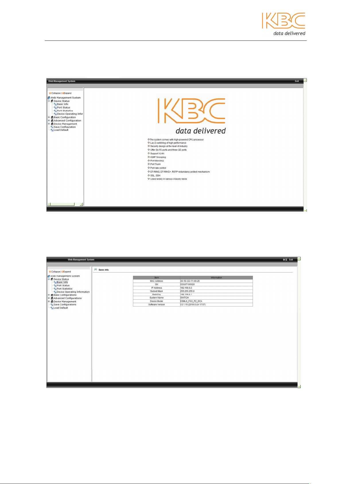
3.1.1.1 Basic Info
This displays the basic switch information: MAC address, Serial Number (SN), IP address,
subnet mask, gateway, system name, device model and software version.
Fig 3-3 Basic Info
Manual_web_mgt_sw-ESML6-P3-Rev 1107
Copyright © KBC Networks Ltd. 2011 Page 6 of 51 www.kbcnetworks.com
Ethernet Switch User Manual
3.1.1.2 Port Status
This page displays the status of all the ports and includes the port ID, administration
status, link state, port speed, full/half duplex and flow control state.
Fig 3-4 Port Status
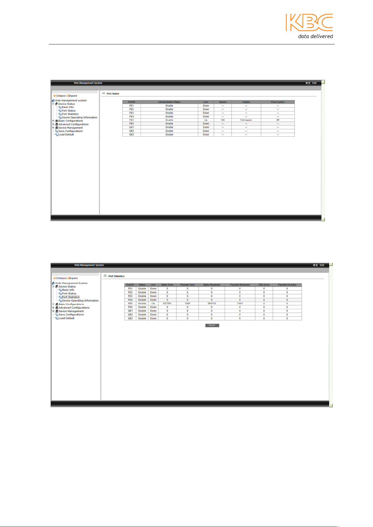
3.1.1.3 Port Statistics
This page displays the port flow statistics of each of the ports.
Fig 3-5 Port Statistics
Manual_web_mgt_sw-ESML6-P3-Rev 1107
Copyright © KBC Networks Ltd. 2011 Page 7 of 51 www.kbcnetworks.com
Ethernet Switch User Manual
3.1.1.4 Device Operating Information
This page displays the device operating time and CPU usage.
Fig 3-6 Device Operating Information
3.1.2 Basic Configurations
The Basic Configurations menu includes six submenus: IP Address, Device Information,
Port Configuration, Change Password, Software Update and Upload & Download.
Fig 3-7 Basic Configurations
Manual_web_mgt_sw-ESML6-P3-Rev 1107
Copyright © KBC Networks Ltd. 2011 Page 8 of 51 www.kbcnetworks.com
Ethernet Switch User Manual
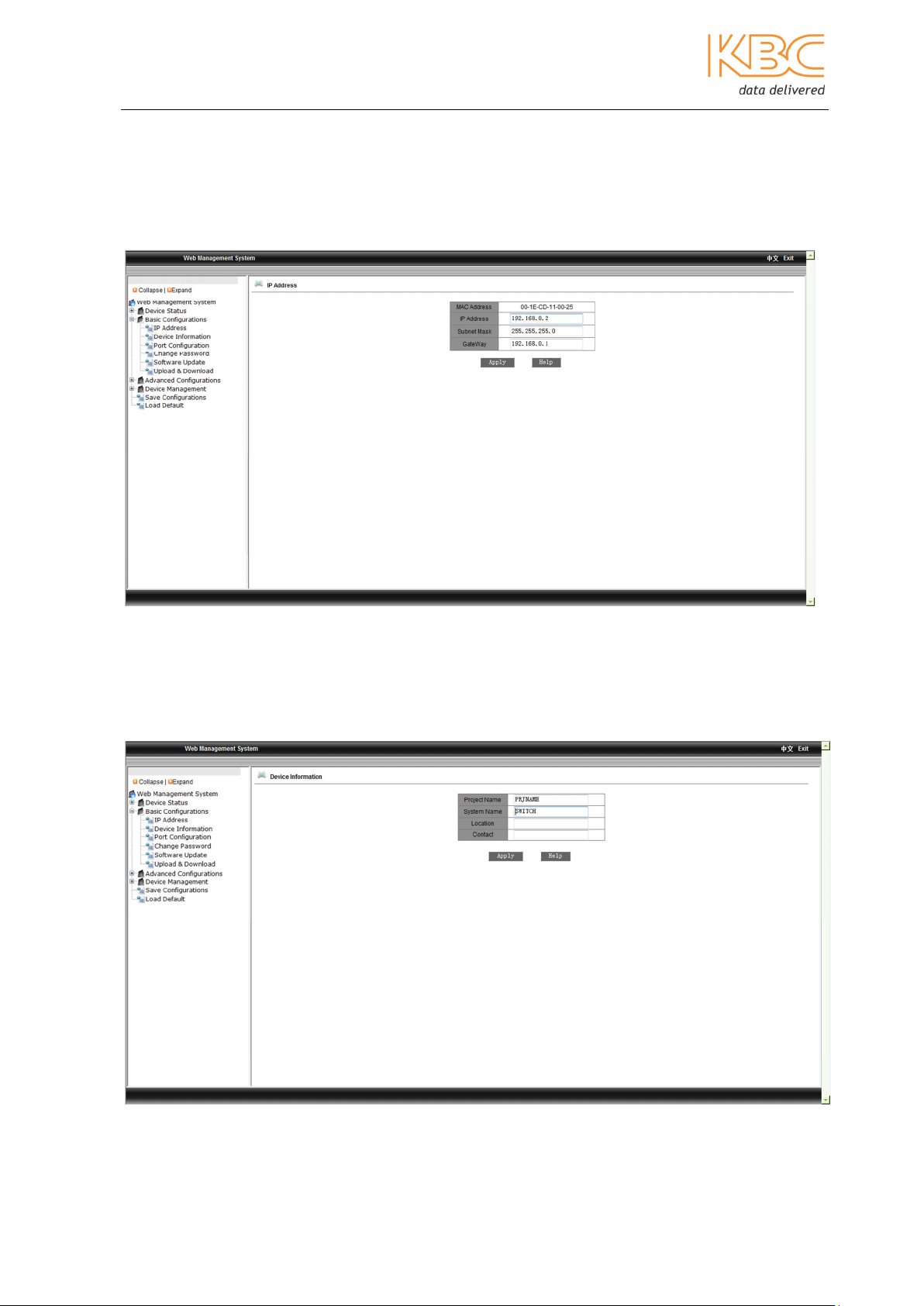
3.1.2.1 IP Address
In this menu the user can modify the IP address, subnet mask and gateway. Select
<Apply> once changes have been made. The switch needs to be rebooted in the ‘Device
Management’ menu option for changes to be made effective.
Fig 3-8 IP Address
3.1.2.2 Device Information
In this menu you are able to enter the project name, system name, location and contact
information. Select <Apply> once changes have been made and wait for confirmation
that they have been accepted.
Fig 3-9 Device Information
Manual_web_mgt_sw-ESML6-P3-Rev 1107
Copyright © KBC Networks Ltd. 2011 Page 9 of 51 www.kbcnetworks.com
Ethernet Switch User Manual
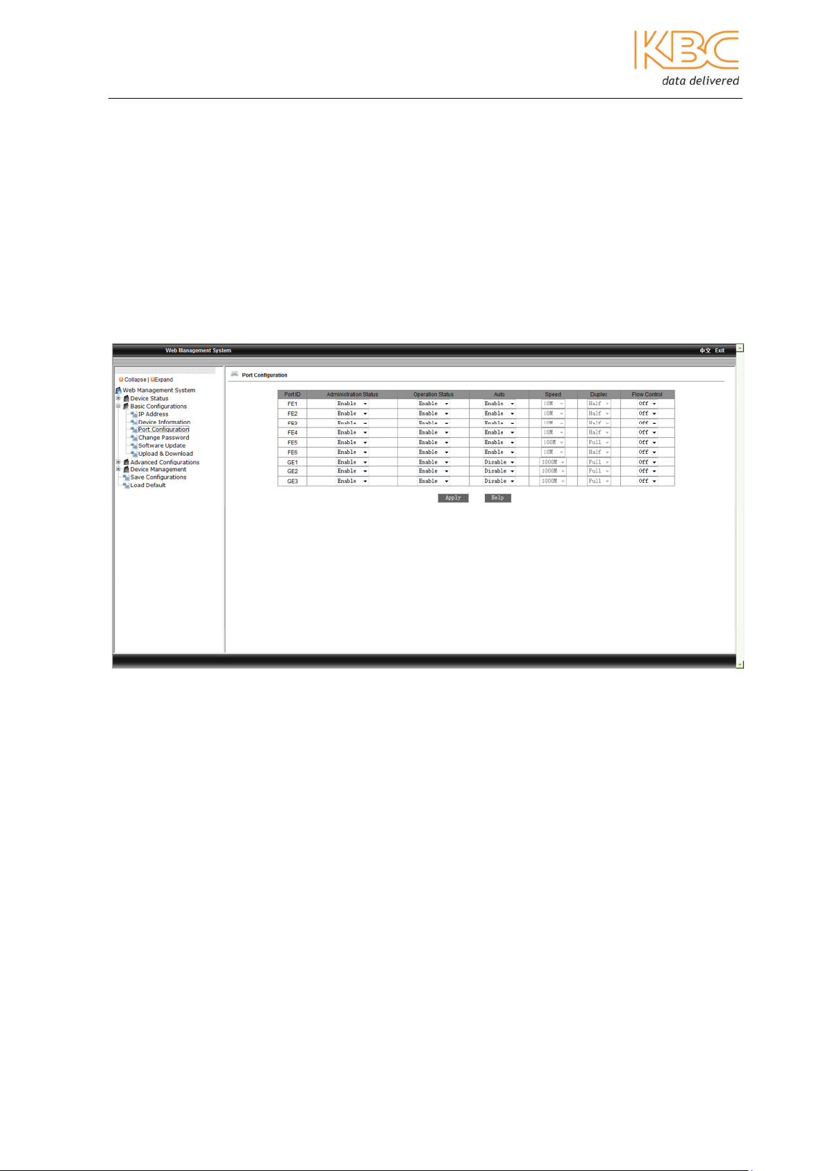
3.1.2.3 Port Configuration
From this menu the user can configure the port administration status (enable/disable),
the operation status (enable/disable) & auto-negotiation (enable/disable), set the port
speed to either 10M or 100M, whether it is full or half duplex and set the switch flow
control (on/off). If enabled the port administration allows the port to be used to connect
to the management interface, if disabled this function is not available. If a port is to be
used the operation status must be enabled and if not in use, disabled. Auto-negotiation
allows auto sensing to be enabled or disabled. For ports 1 to 6 auto-negotiation must be
disabled to allow the speed and full or half-duplex to be fixed. If flow control is on then
the switch can control the speed at which data is sent to ensure that it is not faster than
the receiver is capable.
Select <Apply> once changes have been made.
Fig 3-10 Port Configuration
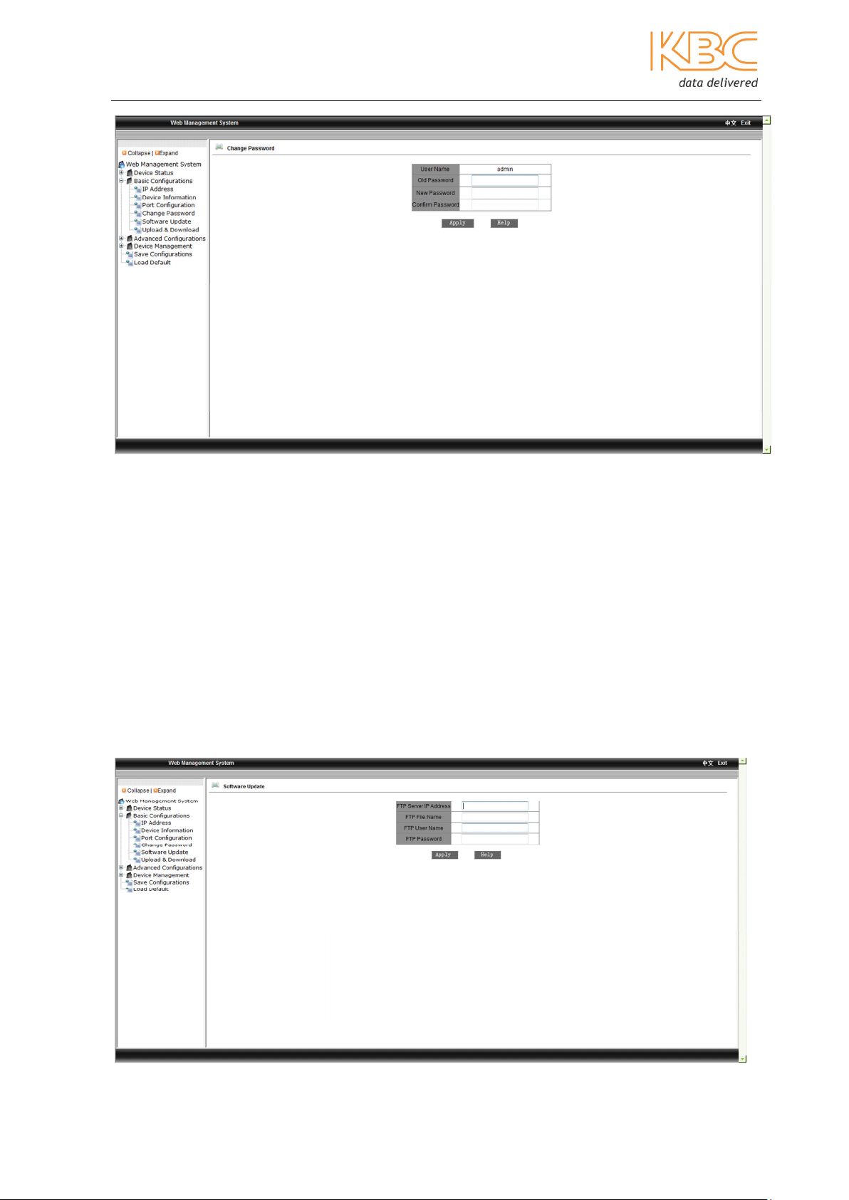
3.1.2.4 Change Password
From this menu the user can enter a new password. Enter the details of the old password
and the new one and then select <Apply> to confirm changes.
Manual_web_mgt_sw-ESML6-P3-Rev 1107
Copyright © KBC Networks Ltd. 2011 Page 10 of 51 www.kbcnetworks.com
Ethernet Switch User Manual
Fig 3-11 Change Password
3.1.2.5 Software Update
Enter the FTP server IP address, FTP file name, FTP user name and FTP password. Select
<Apply> once changes have been made and make a note of the upgraded software ID.
Note: the FTP server address must be on the same subnet as the switch IP address.
Wait for the upgrade to complete, a message will be displayed when it is finished.
The switch needs to be rebooted in the ‘Device Management’ menu option for changes to
be made effective.
Wait for 30 seconds to start up the network management system.
Select the ‘Device Basic Info’ option from the menu to check that the software version
has been successfully upgraded.
Manual_web_mgt_sw-ESML6-P3-Rev 1107
Copyright © KBC Networks Ltd. 2011 Page 11 of 51 www.kbcnetworks.com
Ethernet Switch User Manual
Fig 3-12 Software Update
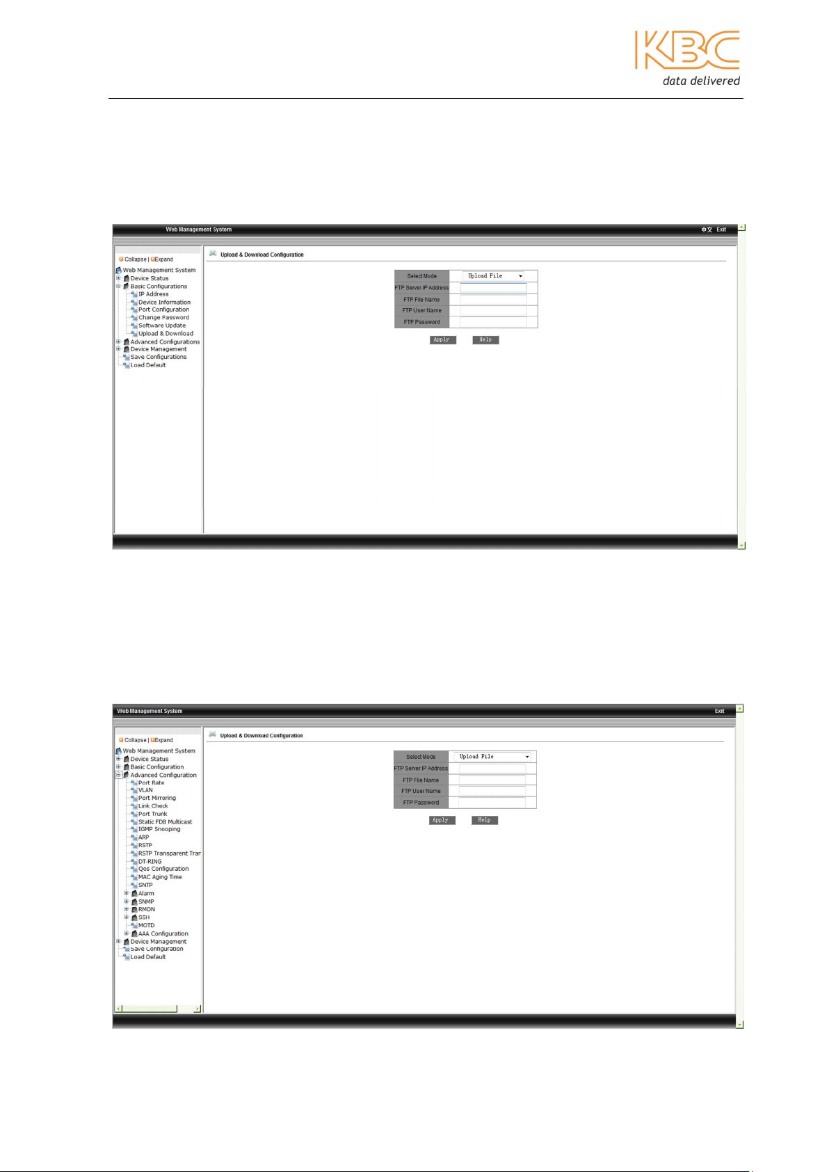
3.1.2.6 Upload & Download
This menu option can be used to upload and download switch configuration information.
Select either upload or download, enter the FTP server IP address, FTP filename, FTP
username and FTP password. Select <Apply> and wait for confirmation.
Fig 3-13 Upload & Download
3.1.3 Advanced Configuration
The Advanced Configurations menu includes twenty submenus: Port Rate, VLAN, Port
Mirroring, Link Check, Port Trunking, Static FDB Multicast, IGMP Snooping, ARP, RSTP,
RSTP Transparent Transmission, DT-Ring, QoS Configuration, MAC Aging Time, SBTP,
Alarm, SNMP, RMON, SSH, MOTD & AAA Configuration.
Manual_web_mgt_sw-ESML6-P3-Rev 1107
Copyright © KBC Networks Ltd. 2011 Page 12 of 51 www.kbcnetworks.com
Ethernet Switch User Manual
Fig 3-14 Advanced Configuration
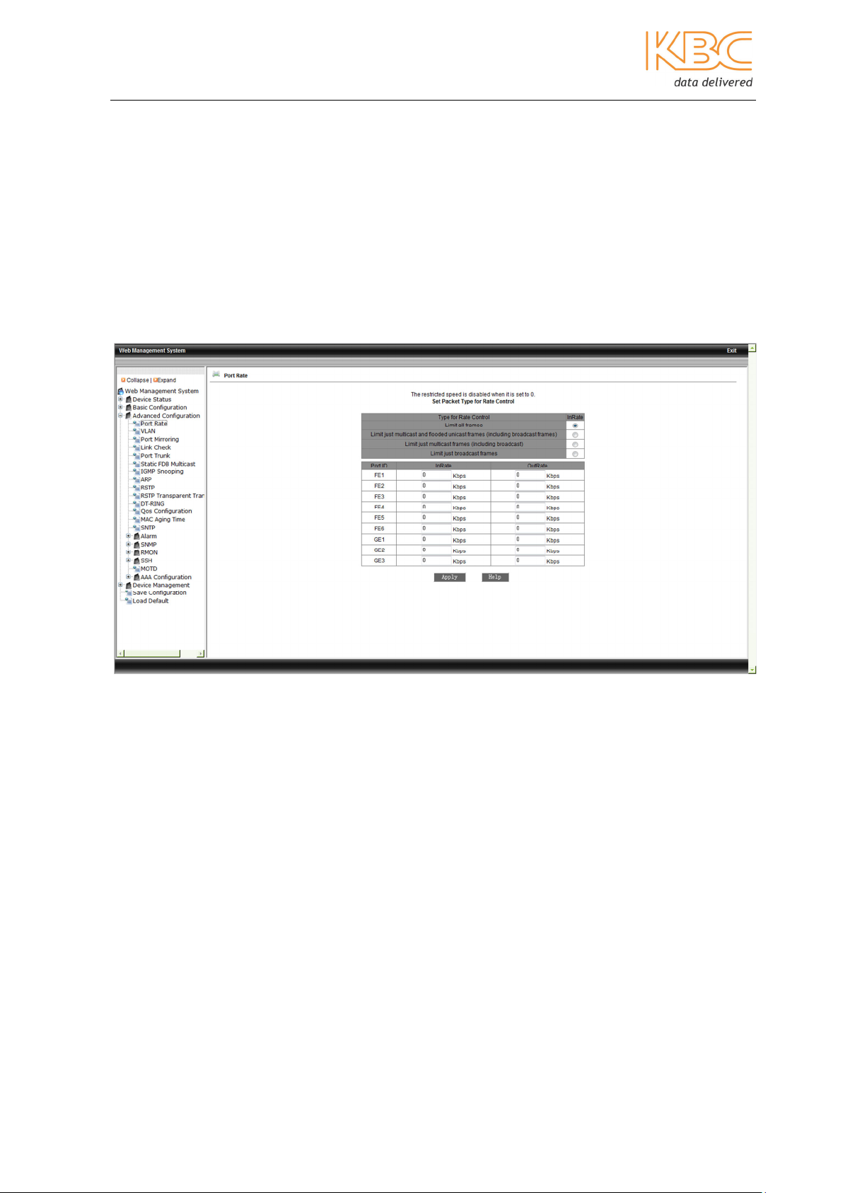
3.1.3.1 Port Rate
Port Rate is used to control Broadcast Storms.
Select the type of rate control from the table, the options are: limit all frames, limit just
multicast and flooded unicast frames (these are the unknown unicast frames and includes
broadcast frames), limit just multicast frames (including broadcast) and limit just
broadcast frames. The range for the 100M ports is 62kps to 100,000kbps and for the
Gigabit ports 62 kbps to 256,000kbps. If the speed is set to 0 the restricted speed is
disabled.
Select Apply> once changes have been made.
Fig 3-15 Port Rate
3.1.3.2 VLAN
VLANs (Virtual Local Area Networks) allow one network to be divided into multiple logical
subnets. The terminal equipment connected to the ports of a switch in the same VLAN
are able to communicate with each other as defined by their logical relationship rather
than their physical connectivity.
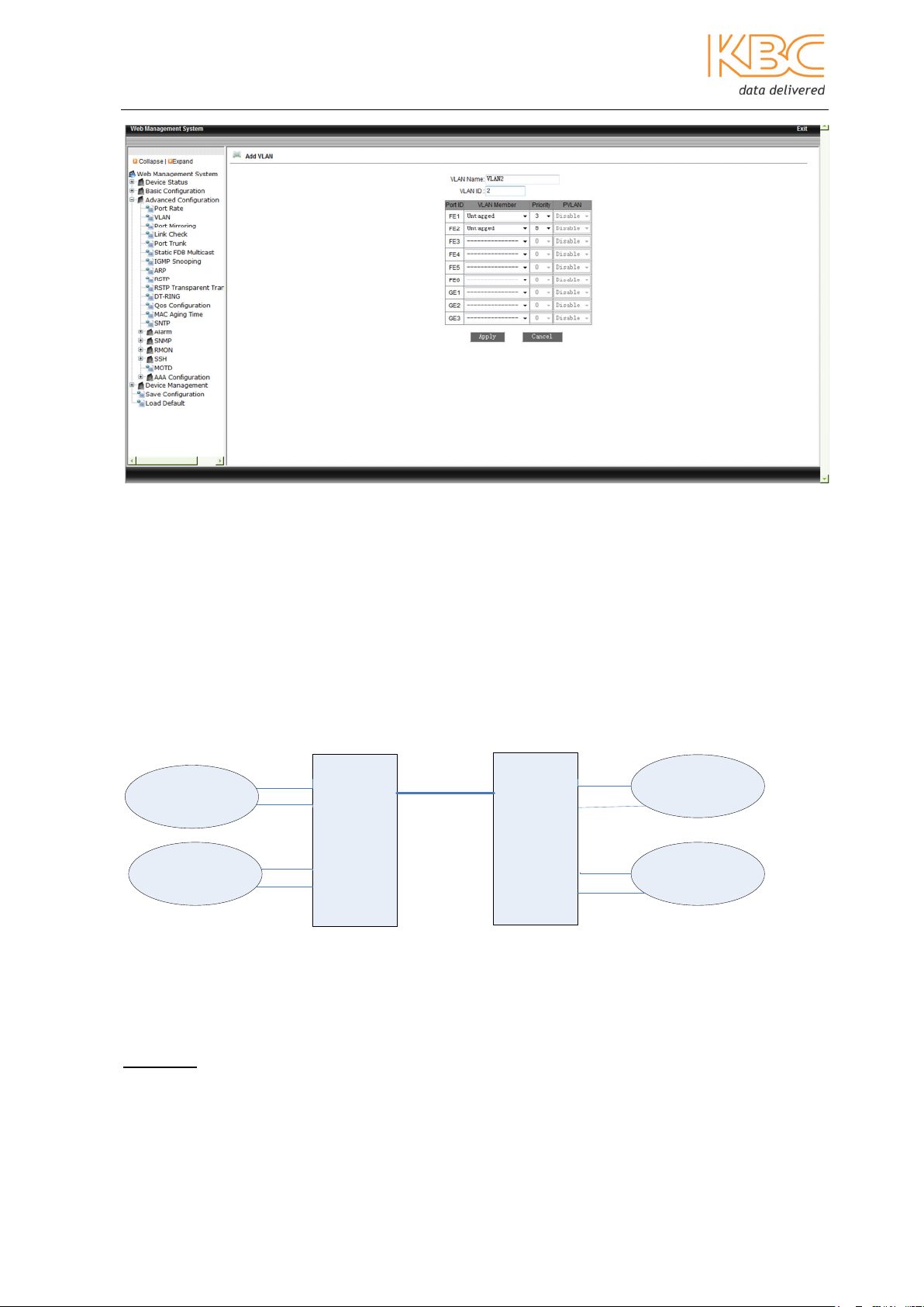
Once in this menu select <Add> to set up a new VLAN. Enter a VLAN name and VLAN ID,
VLAN1 is the default for the switch so the range of ID numbers that can be set is from 2
to 4093.
The members of the VLAN need to be set as either tagged or untagged. If a port is set to
be untagged it is an access port. This is used to connect an end station that is VLANunaware, this port provides connectivity through the switch without the actual end
station being required to support VLAN tagging. If a port is untagged the priority of the
port can be set from 0 to 7.
Manual_web_mgt_sw-ESML6-P3-Rev 1107
Copyright © KBC Networks Ltd. 2011 Page 13 of 51 www.kbcnetworks.com
Ethernet Switch User Manual
Fig 3-16 Add a VLAN
Example:
Switch 1
VLAN 2
VLAN 3
1
2
3
4
5
6
Fig 3-16 Untagged Ports
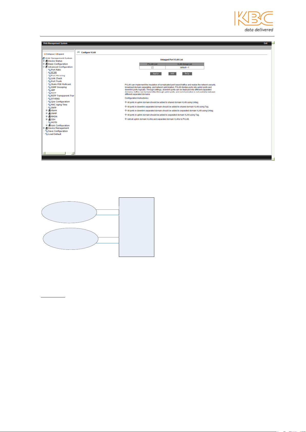
In this example VLAN2 is configured so that port 1 and 2 belong to it and ports 3 and 4
belong to VLAN3. In this situation information on ports 1 & 2 is isolated from ports 3 & 4.
Switch 1:
VLAN2 port 1 = untagged VLAN3 port 3 = untagged
port 2 = untagged port 4 = untagged
Manual_web_mgt_sw-ESML6-P3-Rev 1107
Copyright © KBC Networks Ltd. 2011 Page 14 of 51 www.kbcnetworks.com
Ethernet Switch User Manual
Fig 3-17 Configuring a VLAN
A tagged port is a trunk port. This port is used to interconnect switches that are in the
VLAN-aware domain. The VLAN-aware switch receives the untagged frames from the
end stations, applies the VLAN association rules, and forwards the frames with a tag.
Once the ports have been set select <Apply> to complete the configuration.
To edit or view an existing VLAN select the VLAN name from under the VLAN Group List.
Example:
VLAN 2
VLAN 3
1
2
3
4
Switch 1
5
6
5
6
Switch 2
1
2
3
4
VLAN 2
VLAN 4
Fig 3-18 Tagged ports
In the example in Fig 3-18, Switch 1 and Switch 2 are connected via ports 5 on both
switches, VLAN 2 on Switch 1 is then able to communicate with VLAN2 on Switch 2 via
the uplink port 5. The configuration would need to be as follows:
Switch 1:
VLAN2 port 1 = untagged VLAN3 port 3 = untagged
port 2 = untagged port 4 = untagged
port 5 = tagged port 5 = tagged
Manual_web_mgt_sw-ESML6-P3-Rev 1107
Copyright © KBC Networks Ltd. 2011 Page 15 of 51 www.kbcnetworks.com

Ethernet Switch User Manual
Switch 2:
VLAN2 port 1 = untagged VLAN4 port 3 = untagged
port 2 = untagged port 4 = untagged
port 5 = tagged port 5 = tagged
Fig 3-19 Configuring a tagged VLAN – VLAN2
Fig 3-20 Configuring a tagged VLAN – VLAN 3
Manual_web_mgt_sw-ESML6-P3-Rev 1107
Copyright © KBC Networks Ltd. 2011 Page 16 of 51 www.kbcnetworks.com
Ethernet Switch User Manual
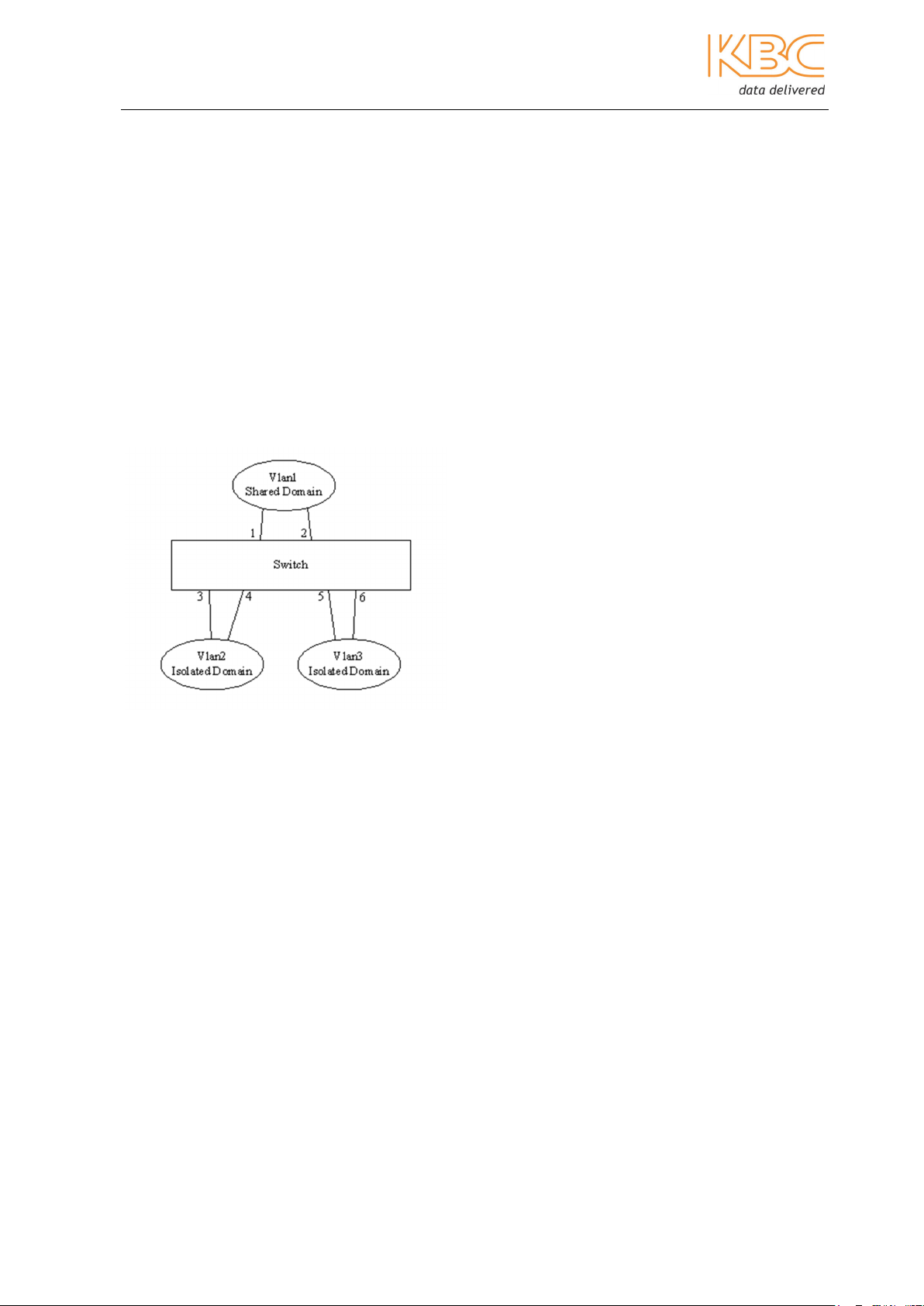
PVLAN
A private VLAN (PVLAN) contains switch ports that cannot communicate with each other
on a switch but can access a shared domain. These ports are called private ports. Each
private VLAN contains one or more private ports, and a single uplink port or uplink
aggregation group.
The PVLAN function should be configured as follows:
• In the shared domain VLAN, add the ports so that the private ports are set as
tagged and the ports within the shared domain are set as untagged.
• In the isolated domain VLANs, group the private ports as untagged members with
only the shared ports tagged, (do not include the ports from the other private
VLAN).
• Add all the VLANs to the PVLAN.
Example:
Fig 3-21 PVLAN
In the example in Fig 3-21 ports 3, 4, 5 & 6 are private ports grouped as VLAN2 and
VLAN3 and VLAN1 is the shared domain. VLAN1 must to be able to communicate with
VLAN2 and VLAN3 however; VLAN 2 & VLAN 3 must not be able to communicate with
each other.
VLAN1 port 1 = untagged port 3 = tagged
port 2 = untagged port 4 = tagged
port 5 = tagged
port 6 = tagged
VLAN2 port 3 = untagged port 1 = tagged
port 4 = untagged port 2 = tagged
VLAN3 port 5 = untagged port 1 = tagged
Port 6 = untagged port 2 = tagged
The VLANs must then be added to the PVLAN.
Manual_web_mgt_sw-ESML6-P3-Rev 1107
Copyright © KBC Networks Ltd. 2011 Page 17 of 51 www.kbcnetworks.com

Ethernet Switch User Manual
Fig 3-22 Add all the VLANs to the PVLAN
3.1.3.3 Port Mirroring
This allows the data from one port to be mapped to another port to allow real-time
monitoring of communications.
Select the mirroring port required from the top list. Select the ports to be mirrored and
whether it is for transmitted data (TX), received data (RX) or both TX&RX. Select
<Apply> for changes to be made effective.
Fig 3-23 Port Mirroring
Manual_web_mgt_sw-ESML6-P3-Rev 1107
Copyright © KBC Networks Ltd. 2011 Page 18 of 51 www.kbcnetworks.com

Ethernet Switch User Manual
3.1.3.4 Link Check
The Link Check status function is used to ensure that a link exists between the
redundant ports in case other devices eg. media converters are between the two
redundant ports. Settings in RSTP, STP or DT-Ring must be configured before the Link
Check function can be enabled.
Enable the Administration Status for the desired port and select <Apply> for changes to
be made effective.
Fig 3-24 Link Status Configuration
Fig 3-25 Link Status
Manual_web_mgt_sw-ESML6-P3-Rev 1107
Copyright © KBC Networks Ltd. 2011 Page 19 of 51 www.kbcnetworks.com
Ethernet Switch User Manual
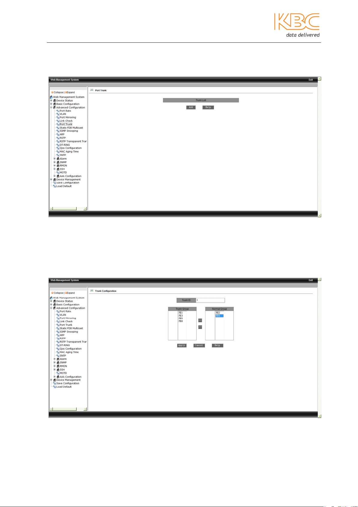
3.1.3.5 Port Trunk
Port trunking or link aggregation is a method by which physical ports are combined into
one logical link to increase bandwidth and improve resilience.
Fig 3-26 Port Trunk
To combine ports select <Add> in the initial screen. Choose a Trunk ID number and then
add the desired ports to the Trunk Group. The ESML6-P3 supports 2 Trunk Groups and
each group can have up to 4 members.
Select <Apply> for changes to be made effective.
Fig 3-27 Configuring a Port Trunk Group
Manual_web_mgt_sw-ESML6-P3-Rev 1107
Copyright © KBC Networks Ltd. 2011 Page 20 of 51 www.kbcnetworks.com
Ethernet Switch User Manual
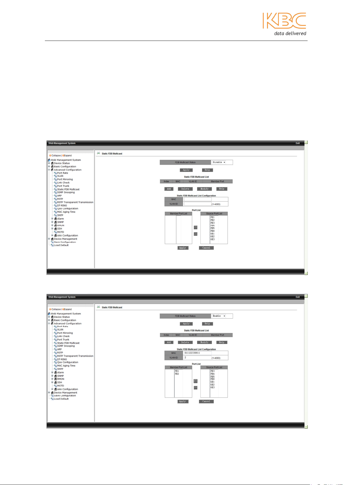
3.1.3.6 Static FDB Multicast
This menu option allows multicast users to be added manually by including them in a
static multicast table. It is simpler, more reliable and faster than dynamic multicast and
does not require the use of protocols. The multicast data is forwarded depending on what
is configured in the static multicast table. Static multicast communication cannot be used
simultaneously with IGMP.
Firstly, enable the FDB Multicast status and select <Apply>. Enter the MAC address,
VLAN ID and select the ports to add to the static multicast address, select <Apply> to
finish. To change any settings select the item in the Static FDB Multicast list and modify
or delete as appropriate.
Note: IGMP Snooping must be disabled before static FDB multicast is enabled.
Fig 3-28 – Static FDB Multicast address
Manual_web_mgt_sw-ESML6-P3-Rev 1107
Copyright © KBC Networks Ltd. 2011 Page 21 of 51 www.kbcnetworks.com
Ethernet Switch User Manual
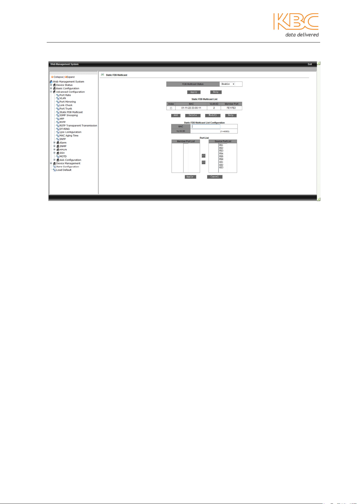
Fig 3-29 Adding a static FDB multicast
Fi 3-30 Successful configuration of static multicast address
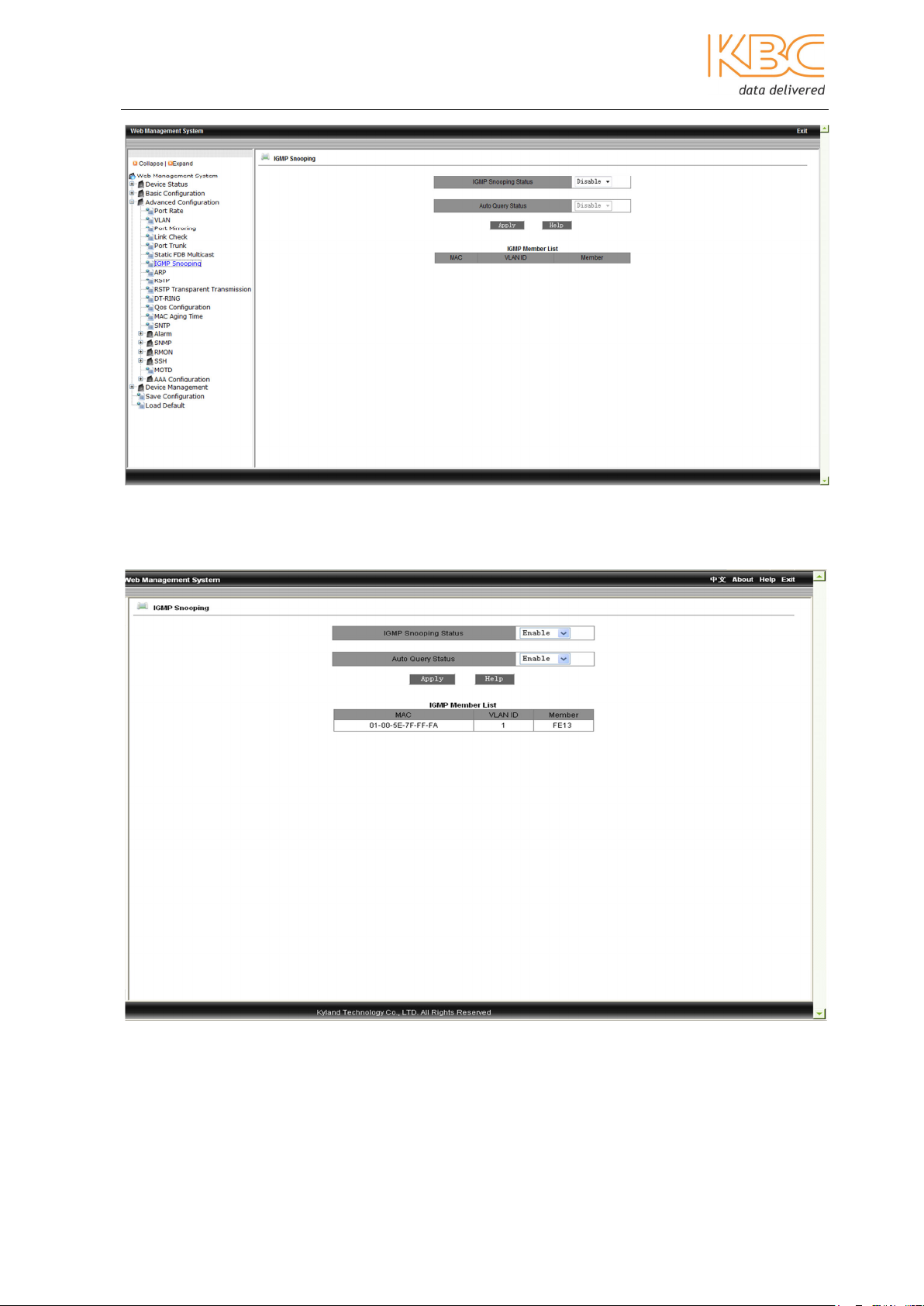
3.1.3.7 IGMP Snooping
Internet Group Management Protocol (IGMP) Snooping is used to restrict the spread of
multicast data in layer 2 and to monitor and analyze IGMP messages. Multicast data is
forwarded based on the set up between the port and the multicast MAC address. When
multicast data is received the switch will know which port should receive the transmitted
multicast data.
In this menu option select enable for both the IGMP snooping status and Auto Query
Status and then select <Apply>. To display the configuration results select ‘IGMPSnooping’ again.
Note: The static FDB multicast must be disabled before enabling IGMP Snooping. The
maximum number of multicast addresses supported is 256.
Manual_web_mgt_sw-ESML6-P3-Rev 1107
Copyright © KBC Networks Ltd. 2011 Page 22 of 51 www.kbcnetworks.com
Ethernet Switch User Manual
Fig 3-31 IGMP Snooping
Fig 3-32 IGMP Configuration
Manual_web_mgt_sw-ESML6-P3-Rev 1107
Copyright © KBC Networks Ltd. 2011 Page 23 of 51 www.kbcnetworks.com
Ethernet Switch User Manual
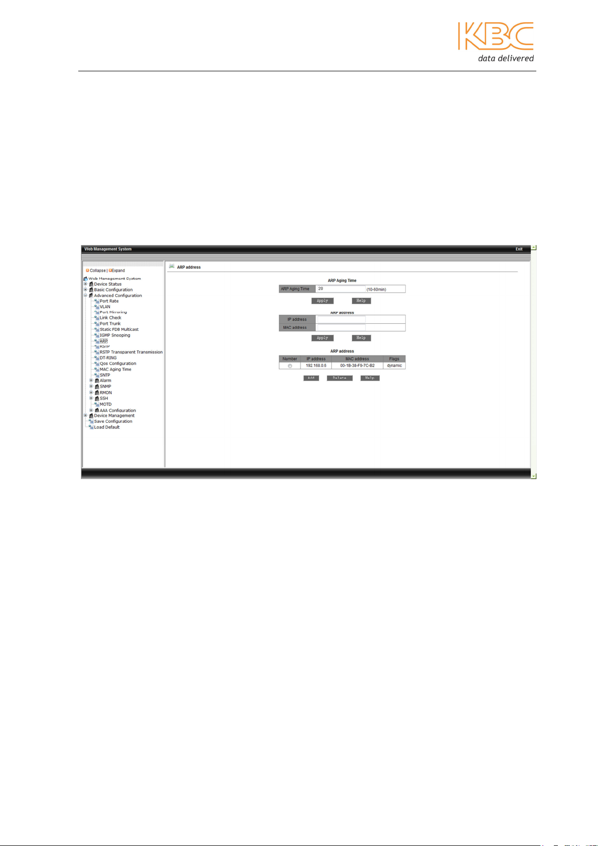
3.1.3.8 ARP
Address Resolution Protocol (ARP) is used to map an IP address to a physical MAC
address on the local area network. The ARP table maintains the relationship between the
IP address and the MAC address.
The aging time is the time in minutes for dynamic entries to remain in the ARP table
before they are removed. When the aging time is reached the switch flushes the entry
from the memory. The MAC address can be either learned by the switch – dynamic or
entered manually.
To configure the ARP aging time enter a figure and select <Apply>. Then configure the
ARP address including IP, MAC addresses and select <Apply> to finish. To delete an ARP
address select the item number from the ARP address list and select <Delete>.
Fig 3-33 ARP
3.1.3.9 RSTP
In this menu both RSTP and STP can be set up. RSTP (Rapid Spanning Tree Protocol) is a
layer 2 management protocol developed from STP (Spanning Tree Protocol) it is
compatible with STP and has all the functionality of STP but is quicker. RSTP defines the
Root Bridge, Root Port, Designated Port, Path Cost and ensures that there are no active
network loops. By creating a tree topology it also optimizes the link backup and path
selection.
Select RSTP or STP to configure this menu. Set the following:
• Spanning Tree Priority - range: 0-65535, default: 32768, step size: 4096
• Hello Time: range - 1-10, default: 2
• Max Age Time - range: 6-40, default: 20
• Forward Delay Time - range: 4-30, default: 15
• Message-age increment to either default or compulsion
Select <Apply
> t
o finish.
Additionally, the protocol status, priority and path cost of each port can be configured.
Manual_web_mgt_sw-ESML6-P3-Rev 1107
Copyright © KBC Networks Ltd. 2011 Page 24 of 51 www.kbcnetworks.com

Ethernet Switch User Manual
Note:
The bridge ID is made up from the device’s bridge priority and MAC address, RSTP uses
these to determine the root bridge and root port. The lower the port priority number, the
higher its actual priority, the device with the lowest bridge ID will be chosen as the root
bridge. The bridge priority is set as the lowest but can be forced to be the root bridge. In
the case of the same priorities, the one with the lowest MAC address is the root bridge.
The Forward Delay Time, Max Age Time and Hello Time must follow these rules:
2 x (Bridge_Forward_Delay – 1.0 seconds) >= Bridge_Max_Age Bridge_Max_Age >= 2
x (Bridge_Hello_Time + 1.0 seconds).
The port path cost is the path expenses of the port link, and is used to calculate the
shortest path, which depends on link bandwidth. The greater the bandwidth, the lower
the link cost. The forwarding path from the current device to root port can be changed by
changing port link cost.
The port priority and port number make up the port ID, which is used for the root port
selection calculation. The smaller the port ID is, the higher the priority it has.
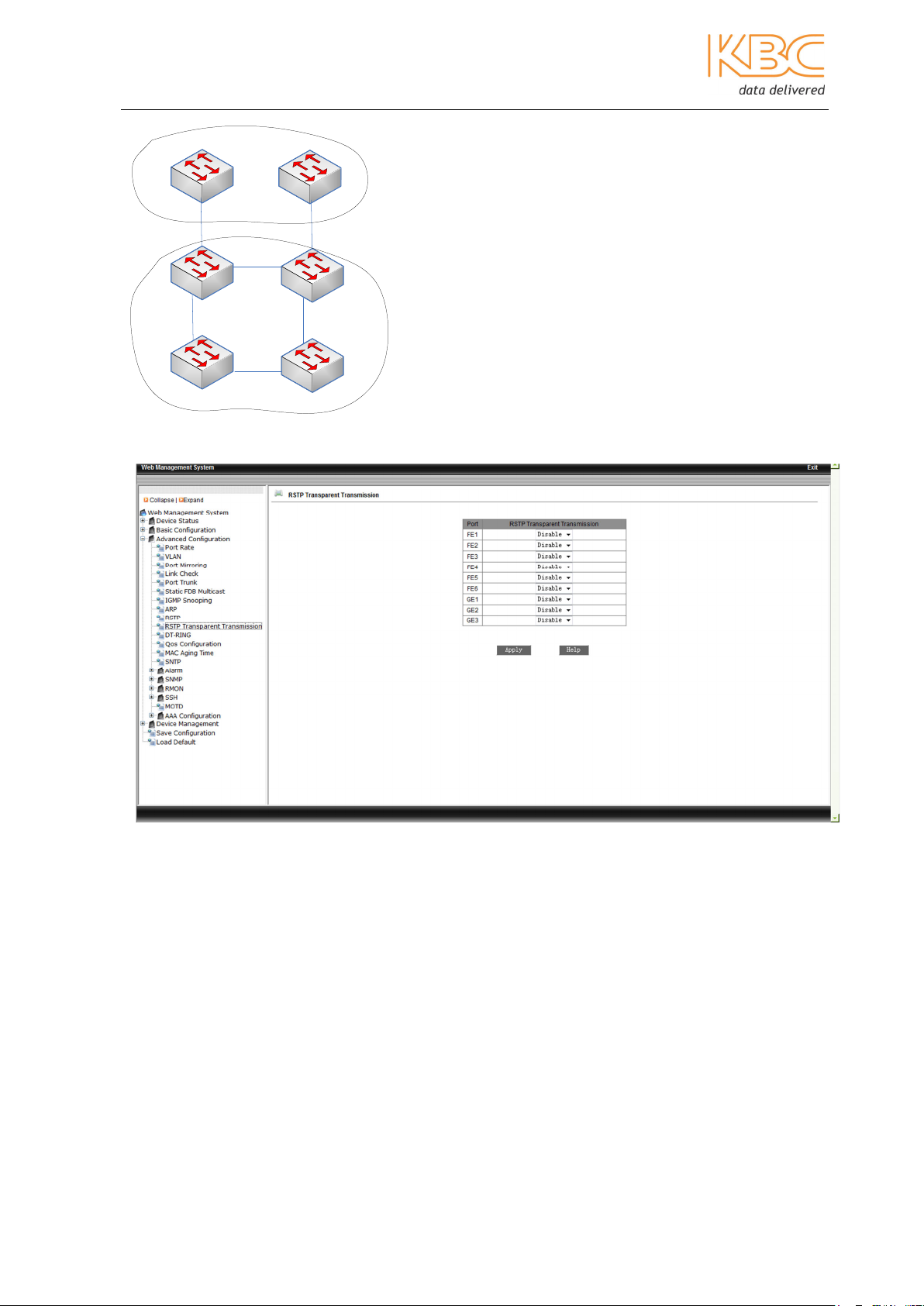
3.1.3.10 RSTP Transparent Transmission
RSTP is a redundant protection protocol and is the IEEE standard, it is not compatible
with the DT-Ring protocol which is available on the ESML6-P3 switch. If an RSTP network
is to be connected to one configured to use DT-Ring then RSTP Transparent Transmission
must be enabled.
RSTP transparent transmission is the process by which the switch forwards the received
RSTP frames to the port set in transparent mode. In an RSTP network the switch is
considered as transparent link.
The benefit of using the RSTP transparent transmission is that the switch can use its own
redundancy protocol which ensures the link reconfiguration time meets industrial
requirements.
In an RSTP domain the switches can be set to use the RSTP protocol and in a DT-Ring
domain they can be set to use the DT-Ring protocol; The RSTP is enabled in the ring port
and the RSTP transparent transmission is set in the switch port connected to the RSTP
domain.
Choose on each port whether RSTP transparent transmission should be enabled or
disabled. Select <Apply> to confirm these choices.
Example:
In the example below switches S1 & S2 are in the RSTP domain and switches A, B, C & D
are in the DT-Ring domain. RSTP transparent transmission is set on the switch ports of A
and C that are connected to the RSTP domain.
Manual_web_mgt_sw-ESML6-P3-Rev 1107
Copyright © KBC Networks Ltd. 2011 Page 25 of 51 www.kbcnetworks.com
Ethernet Switch User Manual
S1
RSTP domain
A
B
DT-ring domain
S2
C
D
Fig 3-34 RSTP Transparent Transmission Example
Fig 3-35 Transparent Transmission
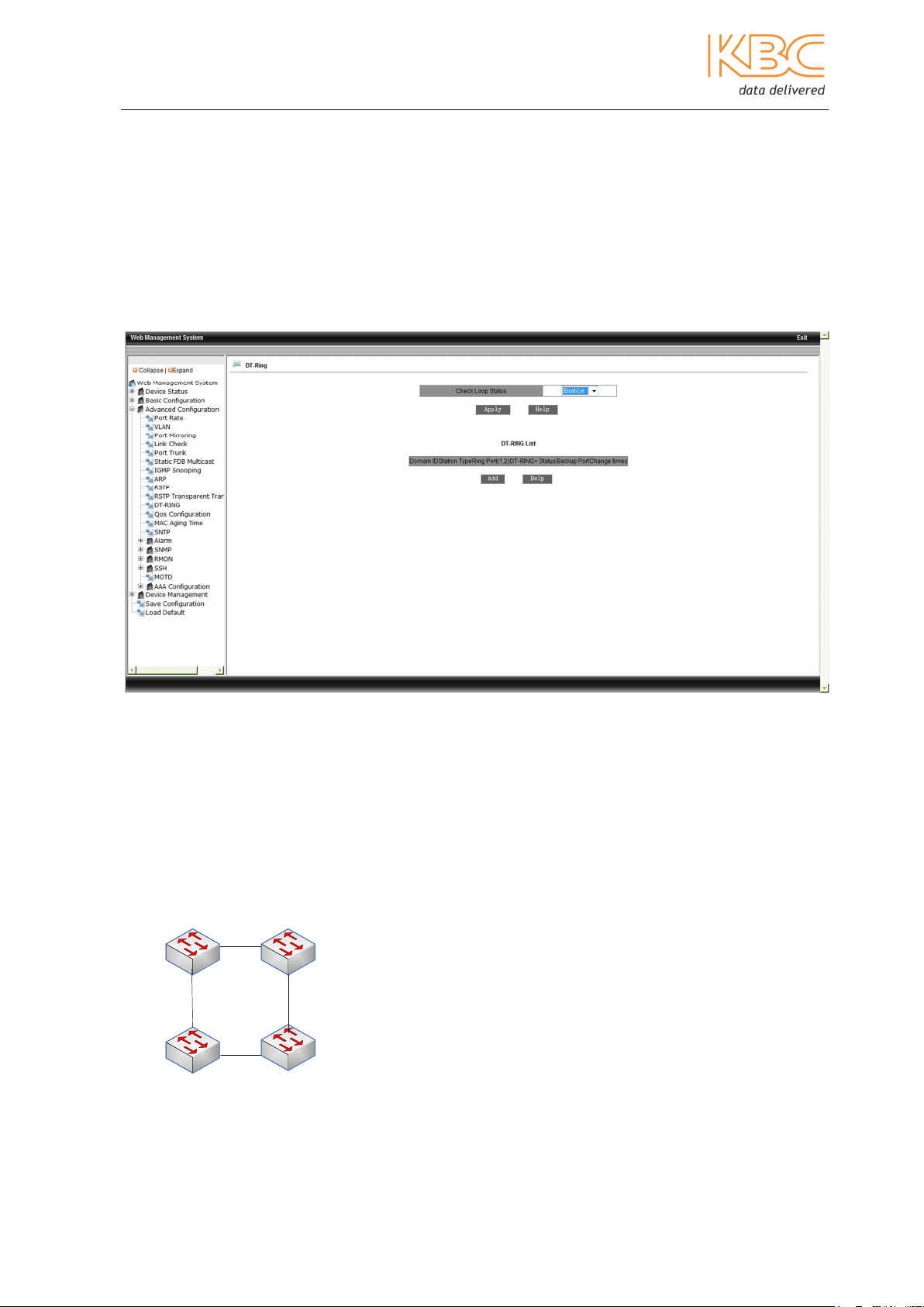
3.1.3.11 DT-Ring
The DT-Ring family is a set of proprietary protocols that are available on the ESML6-P3
switch. They are customized for industrial needs and provide reliable communication and
fast recovery from link and device failures. DT-Ring is used in a single ring topology to
provide redundancy protection and DT-Ring+ is used to provide backup between two DTRings, collectively they are known as DT-PORT protocols.
DT-Ring uses the ring and port status to ensure a redundant ring without creating a loop.
It can only be used with other KBC switches with DT-Ring enabled. If two networks are to
be connected where one is using DT-Ring and the other RSTP, then RSTP Transparent
Transmission must be used, see section 10 above for details.
Manual_web_mgt_sw-ESML6-P3-Rev 1107
Copyright © KBC Networks Ltd. 2011 Page 26 of 51 www.kbcnetworks.com
Ethernet Switch User Manual
Check Loop Status
The Check Loop Status needs to be enabled to ensure that broadcast storms do not
occur. Set this to be either enabled or disabled and select <Apply>. This setting will be
set to disabled by default or if there is a fault detected, if it is set to enabled then the
ring is checked automatically to ensure that a port that is mistakenly included in the ring
does not receive any DT-Ring packets. If the system finds a port has been mistakenly
added to the ring then the port will be blocked.
Fig 3-36 DT-Ring – Check Loop Status
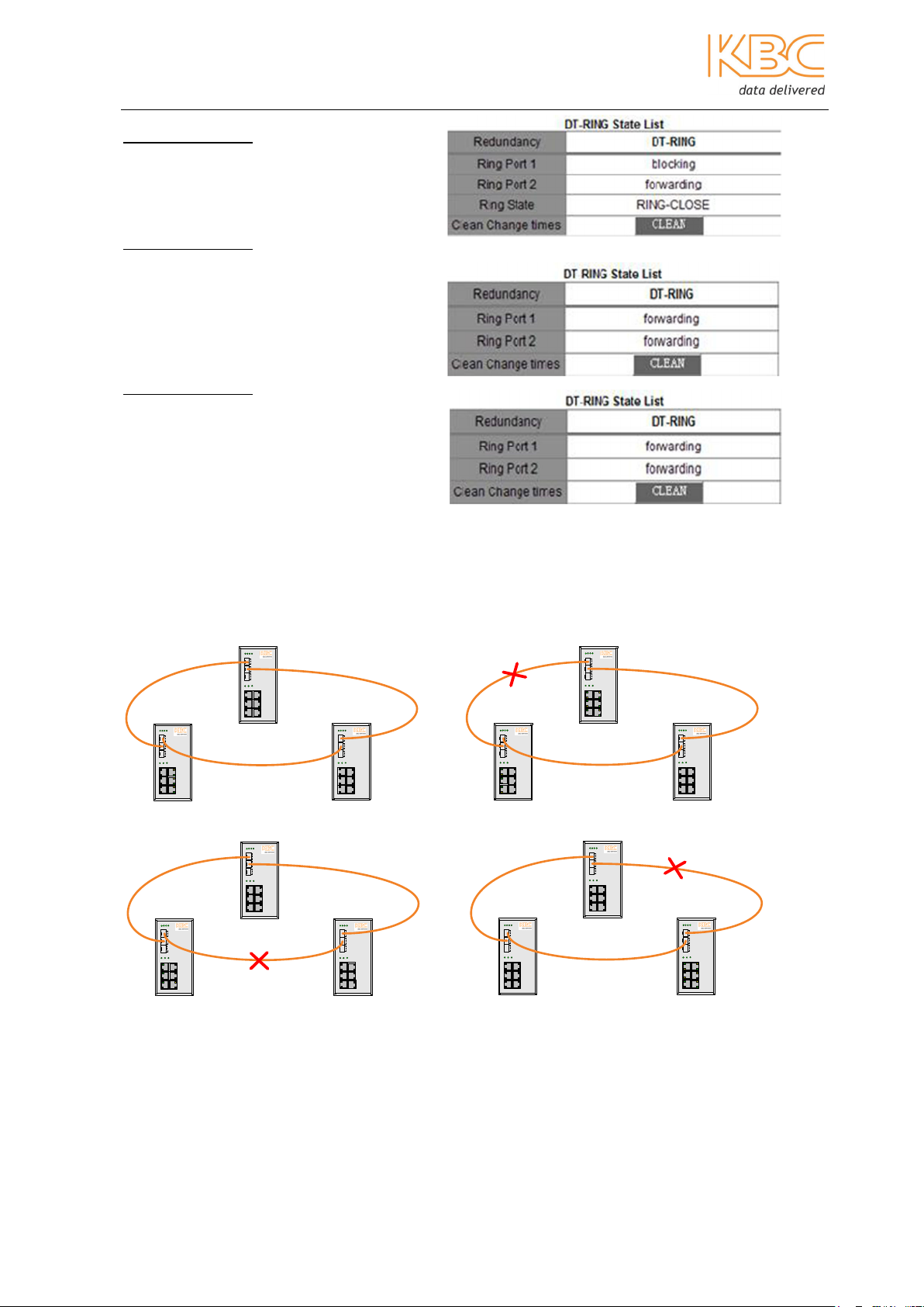
DT-Ring:
For a simple ring network all the switches in one ring must be configured with the same
domain ID and domain name. Only one master can be set in the ring, it is responsible for
checking the loop status of the ring to determine whether its port status should be set as
either forwarding or blocking. The rest of the switches in the ring must be set as slaves
which listen to and forward loop messages and report any link failures to the master
switch.
A
slave
ring
master
B
C
slave
slave
D
Fig 3-38 DT-Ring Configuration
Manual_web_mgt_sw-ESML6-P3-Rev 1107
Copyright © KBC Networks Ltd. 2011 Page 27 of 51 www.kbcnetworks.com
Ethernet Switch User Manual
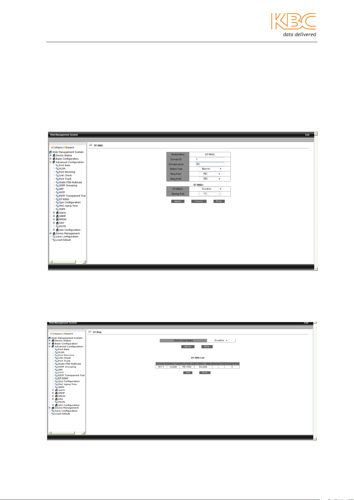
Select DT-Ring from the menu and set the following:
• Domain ID - range 1 – 32
• Domain name
• Station type – master/slave
• Ring ports – FE1 to FE8 and GE1 to GE2
Select <Apply> to finish.
Fig 3-37 DT-Ring Set Up
To view, edit or delete a DT-Ring set up double click on the Domain ID name in the first
screen.
Manual_web_mgt_sw-ESML6-P3-Rev 1107
Copyright © KBC Networks Ltd. 2011 Page 28 of 51 www.kbcnetworks.com

Ethernet Switch User Manual
Fig 3-38 DT-Ring - Editing
It will take you to the following screen where information can be viewed and updated.
Fig 3-39 DT-Ring – Editing
Example:
______ Fiber (dual fibres, Tx->Rx, Rx->Tx)
SW1
T
X
R
X
T
X
R
X
T
X
R
X
SW2
T
X
R
X
T
X
R
X
T
X
R
X
SW3
T
X
R
X
T
X
R
X
T
X
R
X
Manual_web_mgt_sw-ESML6-P3-Rev 1107
Copyright © KBC Networks Ltd. 2011 Page 29 of 51 www.kbcnetworks.com
Ethernet Switch User Manual
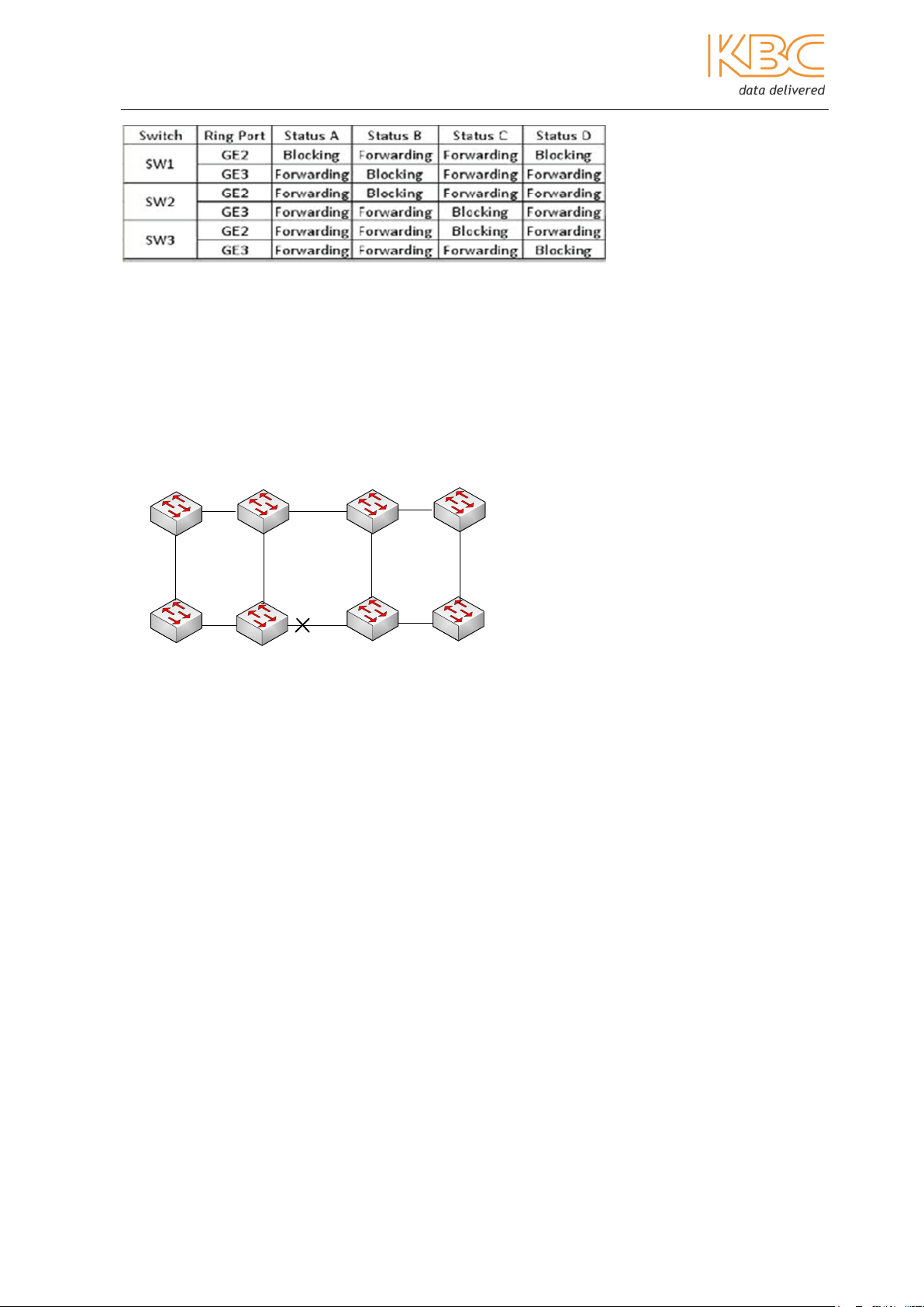
Switch 1 (SW1):
Station type: Master
Ring Port: GE2, GE3
Switch 2 (SW2):
Station type: Slave
Ring Port: GE2, GE3
Switch 3 (SW3):
Station type: Slave
Ring Port: GE2, GE3
Example:
Ring A Ring B
SW2
T
X
R
X
T
X
R
X
T
X
R
X
SW2
T
X
R
X
T
X
R
X
T
X
R
X
SW1
T
X
R
X
T
X
R
X
T
X
R
X
SW1
T
X
R
X
T
X
R
X
T
X
R
X
SW3
T
X
R
X
T
X
R
X
T
X
R
X
SW3
T
X
R
X
T
X
R
X
T
X
R
X
SW2
T
X
R
X
T
X
R
X
T
X
R
X
SW2
T
X
R
X
T
X
R
X
T
X
R
X
SW1
T
X
R
X
T
X
R
X
T
X
R
X
SW1
T
X
R
X
T
X
R
X
T
X
R
X
Ring C Ring D
SW3
T
X
R
X
T
X
R
X
T
X
R
X
SW3
T
X
R
X
T
X
R
X
T
X
R
X
______ Fiber (dual fibres, Tx->Rx, Rx->Tx)
Manual_web_mgt_sw-ESML6-P3-Rev 1107
Copyright © KBC Networks Ltd. 2011 Page 30 of 51 www.kbcnetworks.com
Ethernet Switch User Manual
DT-Ring+
DT-Ring+ is used to provide backup between two rings configured with the DT-Ring
protocol. DT-Ring+ determines the ring and port status depending on the ID of the
backup devices to ensure there is redundancy but no loops. Only one backup port is
allowed on one switch and only two backup ports are allowed in one ring. Backup ports
can be set on either master or slave switches.
G
H
master
master
A
Ring 1 Ring 2
B
C
Backup
port
Backup
port
D
E
F
Fig 3-40 DT-Ring+ Configuration
Set up the DT-Ring as shown above and then set the DT-Ring+ as follows:
• DT-Ring+ - enable/disable
• Backup port - FE1 to FE8 and GE1 to GE2
Select <Apply> to finish.
To view, edit or delete a DT-Ring+ set up double click on the Domain ID name in the first
screen.
Manual_web_mgt_sw-ESML6-P3-Rev 1107
Copyright © KBC Networks Ltd. 2011 Page 31 of 51 www.kbcnetworks.com
Ethernet Switch User Manual
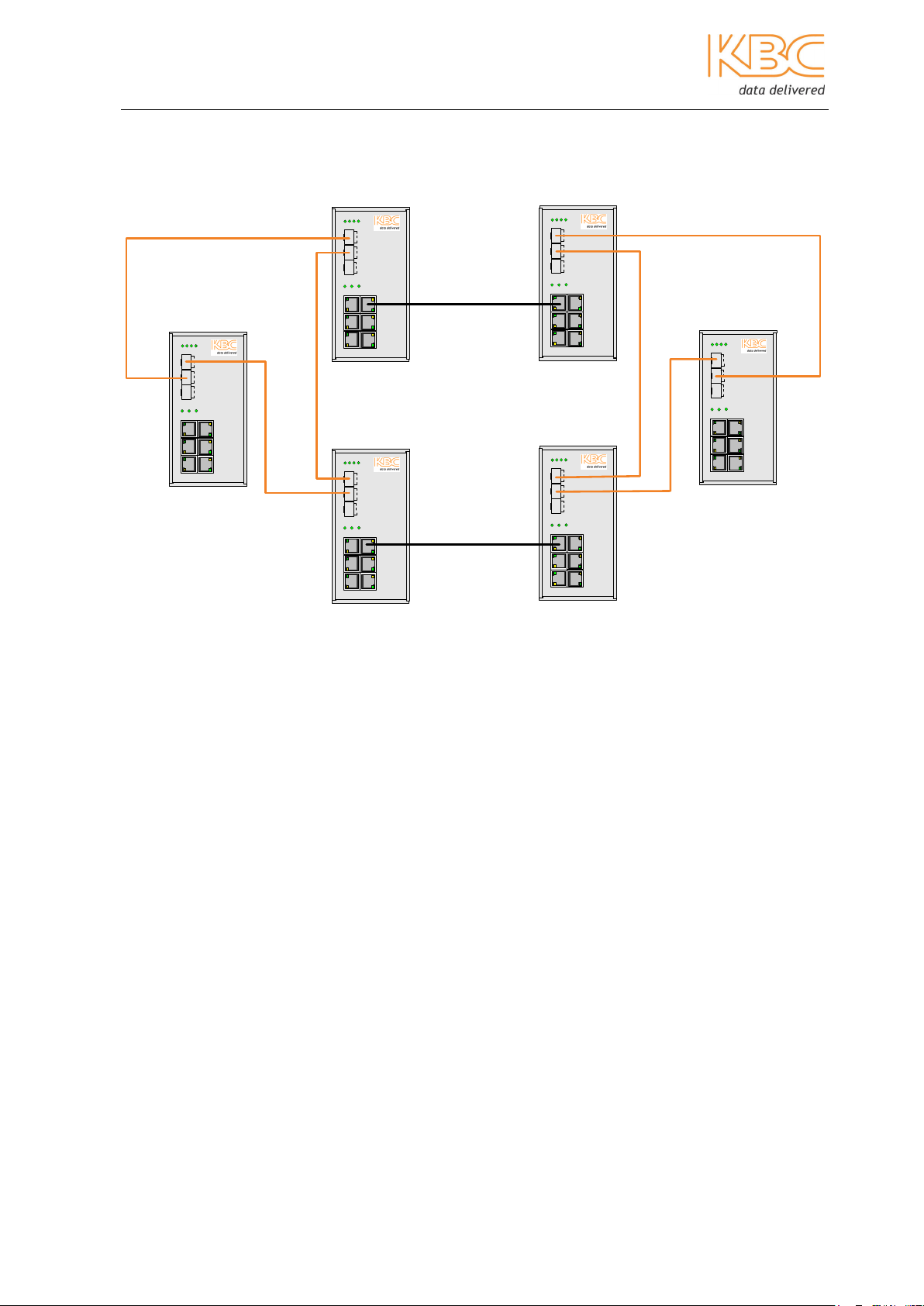
Example:
SW1
DT-RING ENABLE
Ring Port GE2 ,GE3
T
X
R
X
T
X
R
X
T
X
R
X
SW2
DT-RING enable
DT-RING+ enable
Backup Port FE1
T
X
R
X
T
X
R
X
T
X
R
X
T
X
R
X
T
X
R
X
T
X
R
X
SW3
DT-RING enable
Ring Port: GE2,GE3
DT-RING+ enable
Backup Port: FE1
Fiber or Cat5
Crossover Cable
Fiber or Cat5
Crossover Cable
SW5
DT-RING enable
Ring Port: GE2,GE3
DT-RING+ disable
T
X
R
X
T
X
R
X
T
X
R
X
T
X
R
X
T
X
R
X
T
X
R
X
SW6
DT-RING enable
Ring Port: GE2,GE3
DT-RING+ disable
SW4
DT-RING enable
Ring Port: GE2,GE3
T
X
R
X
T
X
R
X
T
X
R
X
______ Fiber (dual fibres, Tx->Rx, Rx->Tx)
_______ Twisted pair
Note:
• Only one backup port is allowed on one switch.
• Only two backup ports are allowed in one ring.
• Backup ports can be set as either master or slave.
• Do not enable DT-Ring+ if there is only one link between two rings.
• Ensure the firmware versions on all switches are the same.
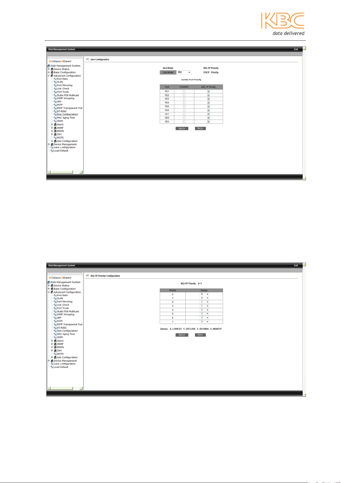
3.1.3.12 QoS
Quality of Service (QoS) is used to provide different priorities for different traffic on the
ports of the switch.
A queue is provided by the buffering structure on the hardware where each port supports
4 priority queues which are given the ID no of 0, 1, 2 or 3. The queue ID number also
sets the queue priority where 0 is the lowest and 3 the highest.
Manual_web_mgt_sw-ESML6-P3-Rev 1107
Copyright © KBC Networks Ltd. 2011 Page 32 of 51 www.kbcnetworks.com
Ethernet Switch User Manual
Fig 3-41 QoS
First, choose the QoS mode either Weighted Round Robin (WRR), STRICT (Strict Priority)
or disabled. WRR schedules data packets according to their weight ratio. In STRICT mode
services with the highest priorities are forwarded first after which the scheduling is
carried out according to the weight ratio. The weight ratio can be set as either 8, 4, 2 or
1 with 8 being the highest and 1 the lowest.
Priority can be based on 802.1P, DSCP (Differentiated Services Code Point) or the port.
To set 802.1P or DCSP hover over the titles and select to enter the relevant screens.
Fig 3-42 802.1P Priority Configuration
Manual_web_mgt_sw-ESML6-P3-Rev 1107
Copyright © KBC Networks Ltd. 2011 Page 33 of 51 www.kbcnetworks.com

Ethernet Switch User Manual
Fig 3-43 DSCP Priority Configuration
Once all configurations have been set select <Apply> to finish.
3.1.3.13 Mac Aging Time
The MAC aging time can be set between 15-3600 seconds and must be a multiple of 15
select <Apply> to save changes. The default time is 300seconds.
Fig 3-44 Mac Aging Time
Manual_web_mgt_sw-ESML6-P3-Rev 1107
Copyright © KBC Networks Ltd. 2011 Page 34 of 51 www.kbcnetworks.com
Ethernet Switch User Manual
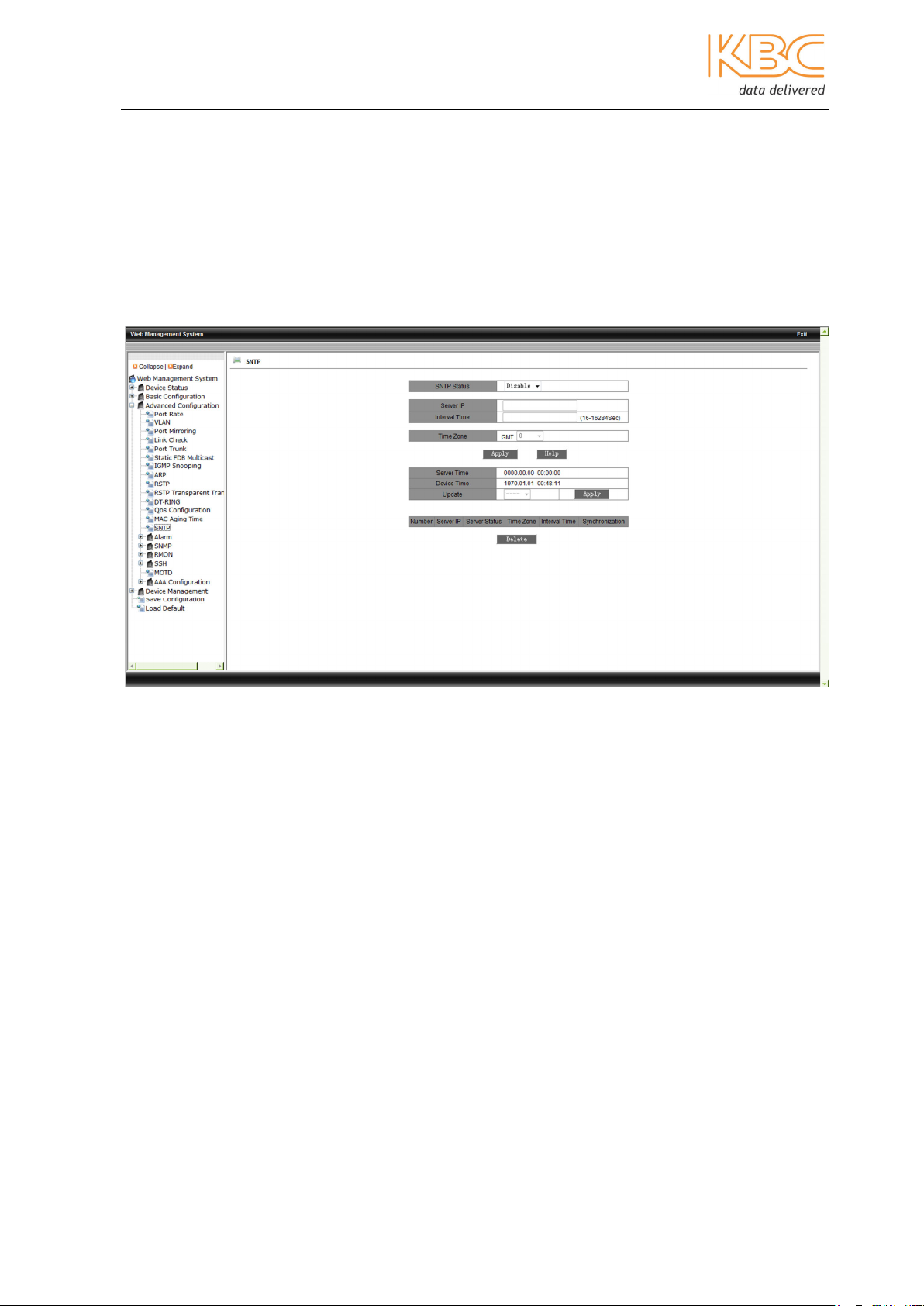
3.1.3.14 SNTP
Simple Network Time Protocol (SNTP) is used to synchronize the clocks of networked
computer systems. The SNTP protocol uses the request and response message
exchanges for the client to adjust the time according to the SNTP server. The ESML6-P3
can work as an SNTP client to calibrate time based information from a SNTP or NTP
server. It can support four SNTP servers at one time. The SNTP client’s request is
broadcast to the SNTP server and the client takes the first one to respond as the ‘active’
server whilst the others are in stand-by mode.
Fig 3-45 SNTP
Enable SNTP Status, the default is disabled, configure the SNTP server’s IP address and
set the interval time to between 16 and 16284 seconds to configure the period for the
synchronization message to be sent. Set the time zone, the default 0 is set as GMT and
the time should be adjusted according to the time zone. The Server Time shows the time
it takes to get from the active SNTP Server and Device Time shows the local time in the
device. Update can be set to either auto or manual, the default is none. The Server state
shows whether the server is providing the SNTP time for the device or is in stand-by
mode.
Manual_web_mgt_sw-ESML6-P3-Rev 1107
Copyright © KBC Networks Ltd. 2011 Page 35 of 51 www.kbcnetworks.com

Ethernet Switch User Manual
3.1.3.15 Alarm
Within the alarm menu there are 2 options: Alarm Show and Alarm Setting.
1. Alarm Show
Fig 3-46 Alarm Show
This page displays the power, port and DT-Ring alarm status. If the port connection is
normal, the alarm status will be shown as Link Up, and if not running correctly, as Link
Down. DT-Ring is shown as Ring Open, if there is an alarm and Ring Close for
reconfiguration status.
2. Alarm Setting
This option allows the set up of the power, port and DT-Ring alarms.
Fig 3-47 Alarm Setting.
Manual_web_mgt_sw-ESML6-P3-Rev 1107
Copyright © KBC Networks Ltd. 2011 Page 36 of 51 www.kbcnetworks.com

Ethernet Switch User Manual
3.1.3.16 SNMP
Simple Network Management Protocol offers a frame structure for low level network
management. The SNMP is widely used to control various network devices. SNMP basic
functions include network performance monitoring, network error checking and analysis
and network device configuration. SNMP can be used to gather statistics, configuration
and testing for a network and also error detection and recovery functions.
An SNMP managed network consists of three key components: a managed device, an
agent (the software which runs on the managed device) and the Network Management
System (NMS) this is the software which runs on the manager. SNMP itself does not
define which information a managed system should offer, it uses available information
defined by Management Information Bases (MIBs). The MIBs describe the structure of
the management data of a device subsystem, they use a hierarchical namespace
containing Object Identifiers (OIDs) and each OID identifies a variable that can be read
or set via SNMP.
In SNMPv2, authentication of clients is performed by a community string which is a type
of password transmitted in clear text. A Trap is a function for the Agent issuing a
message to NMS instead of a response to a request to report emergency alarms. There
can be five Trap server stations.
Within this menu option there are 5 options: SNMP, V3 User Table, V3 Access Table, V3
Context Table and V3 Group Table.
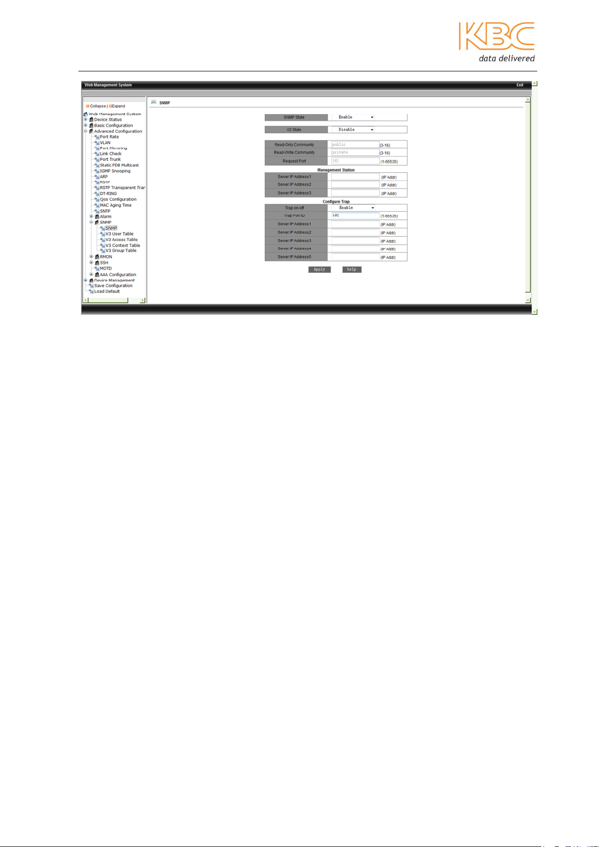
SNMP
Set the SNMP State to ‘Enable’ to enable the SNMP protocol and enable V2 if SNMPv2 is
required, SNMPv3 is supported by default if the SNMP State is enabled. Set the Request
Port to between 1 and 65535, the default is 161, this is the UDP port number for listening
to SNMP requests.
The Management Station shows the IP address of the NMS connected to this device.
Set the Trap on-off to be either enabled or disabled, the Trap port ID to between 1 and
65535, the default being 162 to set the port number for sending Trap messages and the
Server IP addresses to set up the NMS IP addresses for receiving the trap messages.
Select <Apply> to complete the configuration.
Manual_web_mgt_sw-ESML6-P3-Rev 1107
Copyright © KBC Networks Ltd. 2011 Page 37 of 51 www.kbcnetworks.com
Ethernet Switch User Manual
Fig 3-48 SNMP Configuration
SNMPv3
SNMP3 is an architecture extension for SNMPv2, SNMPv3 is totally compatible with
SNMPv2. It provides a valid source which can securely access MIB information by
authentication, encryption and access control. It has two modes User-Based Security
Model (USM) and View-Based Access Control (VBAC).
USM is an authentication strategy for a user and group it belongs to. A combination of a
security model and security level determines what mechanism is used for handling a
SNMP packet.
In SNMPv3 each user belongs to a group, the group defines the access policy for a set of
users. An access policy defines what can be accessed. A group also defines the security
model and security level for its user.
There are 4 tables in SMPv3 besides the original settings for SNMPv2, once all the
combinations are consistent within the tables authenticated then the user will be granted
full authority to access the MIB in the device.
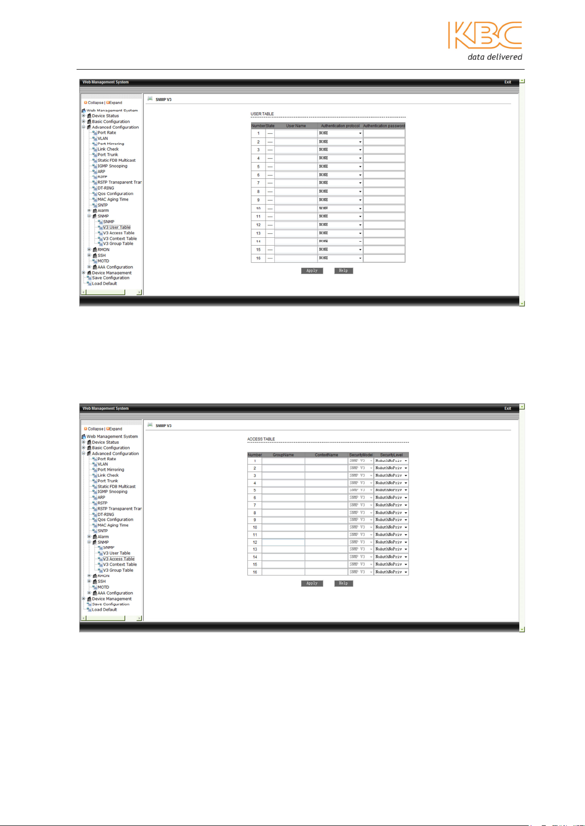
V3 User Table
The User Table is for user authentication with a password.
Set the user name between 4 and 16 letters long. Set the authentication protocol as
either Disabled, HMAC-MD5 or HMAC-SHA and the Authentication password, again a
name between 4 and 16 letters long to create the password for the corresponding user.
Manual_web_mgt_sw-ESML6-P3-Rev 1107
Copyright © KBC Networks Ltd. 2011 Page 38 of 51 www.kbcnetworks.com
Ethernet Switch User Manual
Fig 3-49 V3 User Table
V3 Access Table
There are 2 security levels for the access tables, authnopriv and noauthnopriv.
Set either authnopriv or noauthnopriv, only authentication is supported.
Fig 3-50 SNMPv3 – Access Table
Manual_web_mgt_sw-ESML6-P3-Rev 1107
Copyright © KBC Networks Ltd. 2011 Page 39 of 51 www.kbcnetworks.com

Ethernet Switch User Manual
Context Table
The Context Table is a set of context names that define a set of managed objects that
can be accessed by an SNMP entity.
Set the Context name between 4 and 16 letters long.
Fig 3-51 SNMPv3 – Context Table
V3 Group Table
The Group Table is a set of security names which have the same authority.
Set the Group Name to be 4 to 16 letters long, this name is used as an index to access
the table. If the Security Model is set to SNMPv3 this means USM.
Fig 3-52 SNMPv3 – Group Table
Manual_web_mgt_sw-ESML6-P3-Rev 1107
Copyright © KBC Networks Ltd. 2011 Page 40 of 51 www.kbcnetworks.com
Ethernet Switch User Manual
3.1.3.17 Remote Network MONitoring (RMON) Configuration
RMON supports the monitoring and protocol analysis of LANs. It is used to exchange
network monitoring data between the network monitor and the console system in a
client/server configuration. RMON provides distributed, programmable protocol analysis.
The RMON function allows the user to operate among multiple manufacturers for SNMP
management and monitoring agents. It offers a standard for a group of MIBs to allow the
collection of network statistics unavailable via SNMP. Domain values can be set for critical
parameters so that alarm signals are sent automatically.
This menu option contains RMON statistics, RMON history, RMON alarm and RMON event.
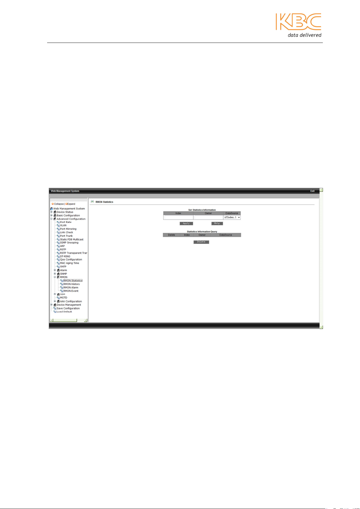
a. RMON Statistics
To configure the RMON statistics fill in the index range, values must be between 1 –
65535, the owner name values between 1 – 32 and select port the range is if Index 1-
10. Select <Apply> to save any changes.
Fig 3-52 RMON Statistics
b. RMON History
To configure the RMON History fill in the index no. (range: 1-65535), owner name
(range: 1-32), select port (range: ifindex 1-10), sampling no. (range: 1-65535, default:
50), sampling space (range: 1-3600, default:1800). Select <Apply> to save changes.
Manual_web_mgt_sw-ESML6-P3-Rev 1107
Copyright © KBC Networks Ltd. 2011 Page 41 of 51 www.kbcnetworks.com

Ethernet Switch User Manual
Fig 3-53 RMON History
c. RMON Alarm
Select the alarm node from the MIB node list and double click, and the OID will be filled
in automatically. Fill in index no. (range: 1-65535), owner name (range: 1-32), select
port (range: ifindex 1-10), sampling type (Absolute/Delta), alarm type (Rising
Alarm/Falling Alarm/Rise or Fall Alarm), sampling space (range: 1-65535), rising
threshold (1-65535), falling threshold (1-65535), rising event index (1-65535) and
falling event index (1-65535). Select <Apply> to save any changes.
Fig 3-54 RMON Alarm
Manual_web_mgt_sw-ESML6-P3-Rev 1107
Copyright © KBC Networks Ltd. 2011 Page 42 of 51 www.kbcnetworks.com
Ethernet Switch User Manual
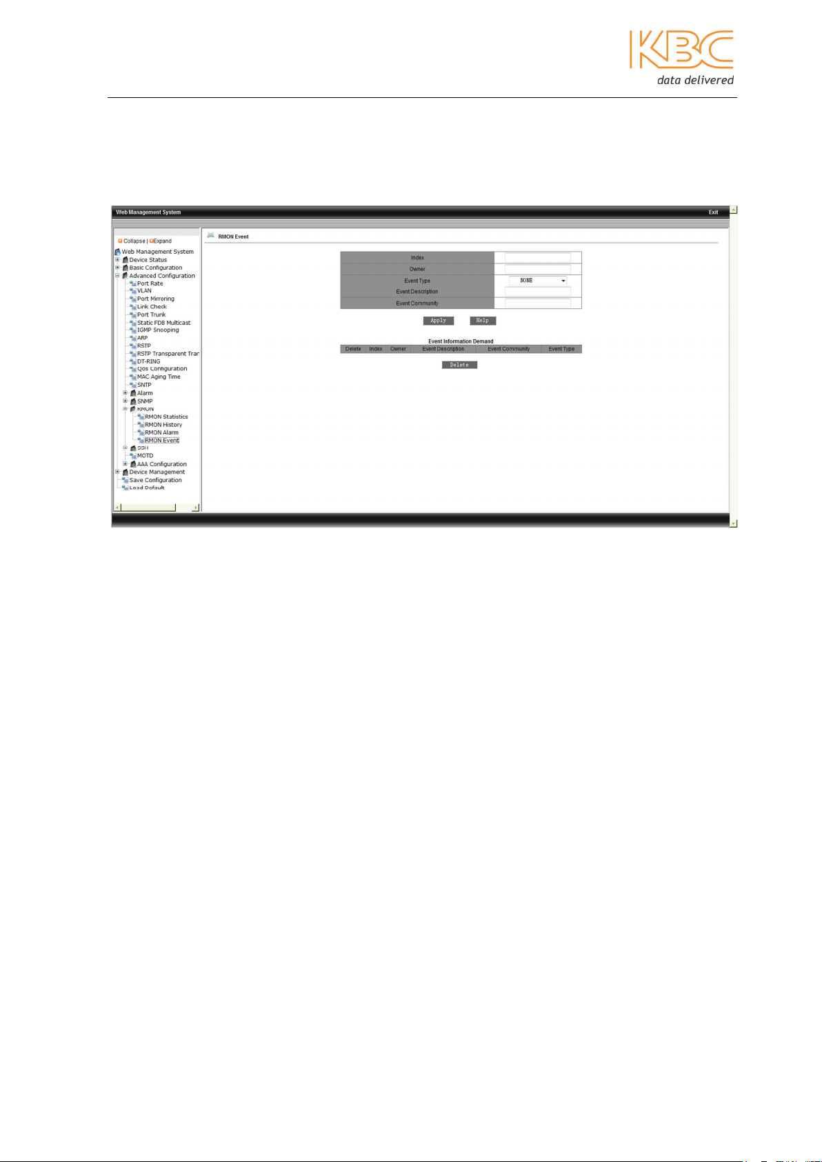
d. RMON Event
Fill in index no. (range: 1-65535), owner name (range: 1-32), event type (LOG/SNMPTrap/Log and Trap), event description (range: 1-127), event community (event trap
receiving community: 1-127). Select <Apply> to save any changes.
Fig 3-55 RMON Event
3.1.3.18 SSH
Secure Shell (SSH) is the standard remote login shell protocol used with TCP/IP where
both authentication and the session are encrypted. It is used to encrypt the transmission
data, stop data being intercepted during transmission, prevent DNS and IP spoofing and
improve the transmission rate as the data is compressed. SSH can replace Telnet and
can provide a secure channel for FTP, POP and PPP. SSH is made up of server and client
software.
Two methods of authentication are supported: password authentication and public key
authentication.
a. SSH Server Configure
Enable the SSH state, set the authentication retry times to between 1 and 10 this is the
maximum retry times before the SSH server refuses to connect. The Time Out can be set
to between 60 and 300, this is how long the SSH Client will maintain a connection when
there is no data input. The Local Key Pair must be set to create or destroy, this has to be
set to create before the SSH server is enabled.
Manual_web_mgt_sw-ESML6-P3-Rev 1107
Copyright © KBC Networks Ltd. 2011 Page 43 of 51 www.kbcnetworks.com

Ethernet Switch User Manual
Fig 3-56 SSH Server Configure
b. SSH User Manager
This shows the local key value and will be filled after using the create button.
The Username should be set to between 3 and 20 letters. The Authentication should be
set to either public key or password. If password is chosen then a name between 3 and 8
characters should be entered and if a public key is chosen then a key needs to be chosen
from the list.
Fig 3-57 SSH User Manager
Manual_web_mgt_sw-ESML6-P3-Rev 1107
Copyright © KBC Networks Ltd. 2011 Page 44 of 51 www.kbcnetworks.com
Ethernet Switch User Manual
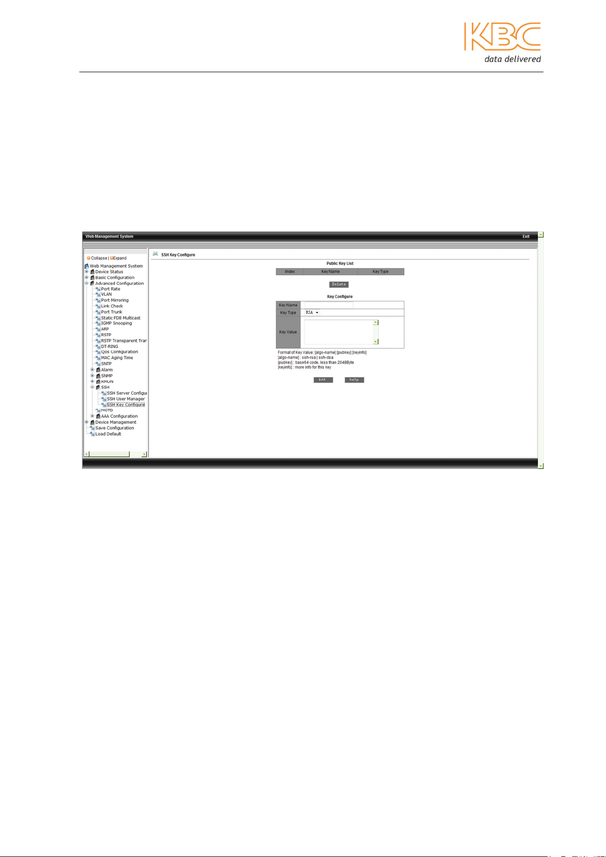
c. SSH Key Configure
A Key name needs to be entered of between 3 and 20 characters which is the name of
the client key. Only RSA is supported. The Key value should be set as follows:
[algo-name] [pubkey] [keyinfo] [algo-name] : ssh-rsa | ssh-dsa [pubkey] : base64 code,
less than 2048Byte [keyinfo] more info for this key.
The publci key for the client, usually created by Putty and pasted here in the server, the
private key is stored in the client.
Fig 3-58 SSH Key Configure
Using password authentication
Create a local key pair for the SSH Server, enable SSH protocol, add a new user with
<username, password>, use Putty to connect the server IP then input the username and
password.
Using public key authentification
Create a local key pair for the SSH Server, enable the SSH protocol. Use Putty to create
a key pai, store the private key in the client and paste the public key content in the Key
Value in the SSH key configuration menu, add a keyname to create an entry in the list.
Add the key authentication user with <username, keyname>. Use Putty to connect the
server IP then in the Putty category connection SSH-Auth, browse the private key file,
then open and input the username.
3.1.3.19 MOTD
Message of the Day provides a user method to edit the login interface. It is enabled by
default. There are four options for information: serial number; system name; location or
contact which will be shown in the login interface of the web, telnet or console. If you
want it to remain blank then enter the <space> key.
Manual_web_mgt_sw-ESML6-P3-Rev 1107
Copyright © KBC Networks Ltd. 2011 Page 45 of 51 www.kbcnetworks.com
Ethernet Switch User Manual
Fig 3-59 MOTD
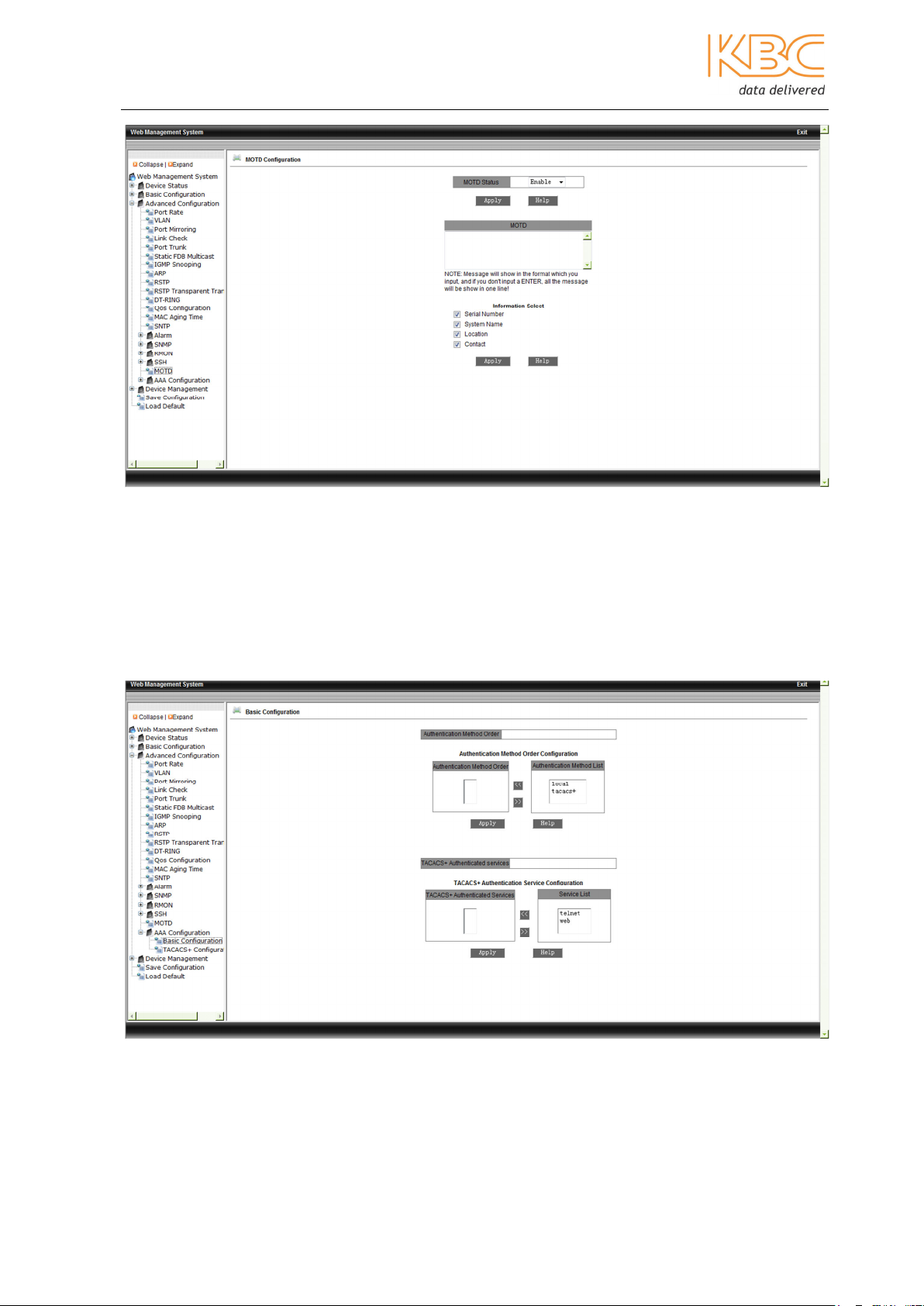
3.1.3.20 AAA Configuration
Authentication, Authorization and Accounting (AAA). Authentication is used to check if
the user has access rights. Authorization is used to determine which service can be used
for the Authorisation User and Accounting records the network resource being used.
First, select the autentcation method either local or TACACS+. If TACACS+ is selected
then select either web or telnet.
Fig 3-60 AAA - Basic Configuration
Next configure the TACACS+ server. For this you will need the TACACS+ server software.
Manual_web_mgt_sw-ESML6-P3-Rev 1107
Copyright © KBC Networks Ltd. 2011 Page 46 of 51 www.kbcnetworks.com

Ethernet Switch User Manual
Fig 3-61 – TACACS+ Configuration
3.1.4 Device Management
Device Management contains two further menus Reboot and Logout.
a. Reboot
By selecting Reboot the switch is restarted.
Fig 3-62 Reboot
Manual_web_mgt_sw-ESML6-P3-Rev 1107
Copyright © KBC Networks Ltd. 2011 Page 47 of 51 www.kbcnetworks.com
Ethernet Switch User Manual
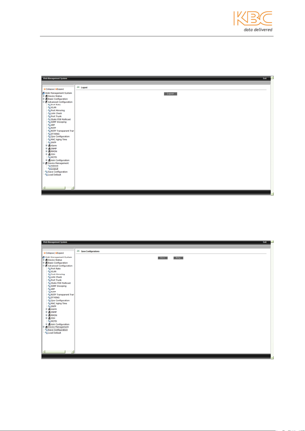
b. Logout
Select the Logout button to logout.
Fig 3-63 Logout
3.1.4.1 Save Configuration
Use this menu option to save all configurations.
Fig 3-64 Save Configuration
Manual_web_mgt_sw-ESML6-P3-Rev 1107
Copyright © KBC Networks Ltd. 2011 Page 48 of 51 www.kbcnetworks.com
Ethernet Switch User Manual
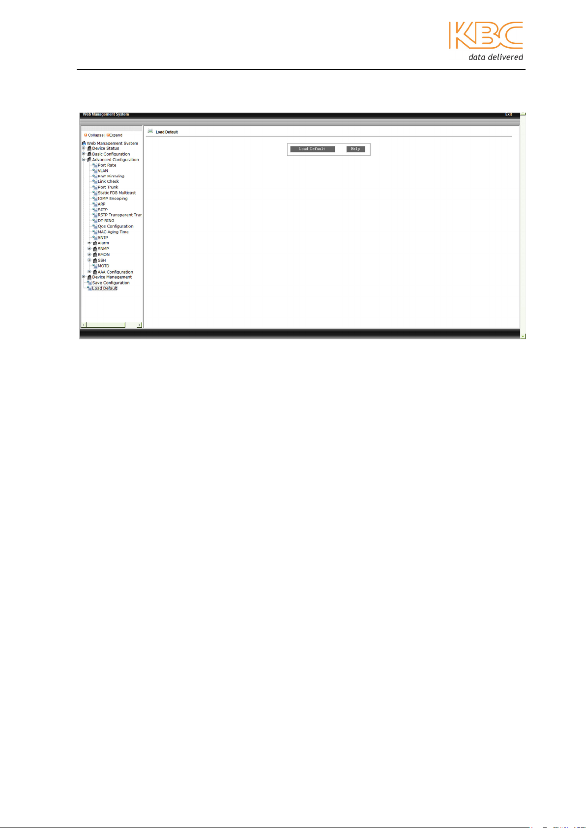
3.1.4.2 Load Default
Use this menu option to restore the default configuration to the switch.
Fig 3-65 Load Default
Manual_web_mgt_sw-ESML6-P3-Rev 1107
Copyright © KBC Networks Ltd. 2011 Page 49 of 51 www.kbcnetworks.com

data delivered
Ethernet Switch User Manual
KBC Networks
25691 Atlantic Ocean Drive
Suite 3B
Lake Forest, CA 92630
U.S.A
Americas
Phone: 1-949-297-4930
Fax: 1-949-297-4933
KBC Networks Ltd., EMEA
KBC Networks Ltd.
Barham Court
Teston, Maidstone
Kent, ME18 5BZ
United Kingdom
Phone: +44(0)1622 618787
Fax: +44(0)20 7100 8147
Email:
Web: www.kbcnetworks.com
Manual_web_mgt_sw-ESML6-P3-Rev 1107
Copyright © KBC Networks Ltd. Page 50 of 51 www.kbcnetworks.com
info@kbcnetworks.com
 Loading...