

KBC ESML6-FL2-M2, ESML6-FL2-S2 User Manual

Ethernet Switch
User Manual
ESML6-FL2-M2
ESML6-FL2-S2

Ethernet Switch User Manual
Inst_manual_hw-ESML6-FL2-Rev_1010
Copyright © KBC Networks Ltd. Page 2 of 20 www.kbcnetworks.com
TABLE OF CONTENTS
1 OVERVIEW ...................................................................... 3
1.1 INTRODUCTION ............................................................................................ 3
1.1.1 ESML6-FL2 ......................................................................................... 3
1.2 TECHNICAL SPECIFICATION .............................................................................. 4
2 INSTALLATION ................................................................. 5
2.1 PACKAGE CONTENTS ...................................................................................... 5
2.2 CONFIGURATIONS ......................................................................................... 5
2.2.1 Physical Connections ........................................................................... 6
2.3 INSTALLATION METHOD ................................................................................... 7
2.3.1 DIN Rail Mount ................................................................................... 7
2.3.2 Wall-mount ........................................................................................ 7
2.4 ETHERNET RJ45 CONNECTIONS ......................................................................... 8
2.4.1 RJ45 Ethernet Ports ............................................................................ 8
2.4.2 Uplink Redundant Ethernet RJ45 ports ................................................... 8
2.5 FIBER OPTIC CONNECTIONS ............................................................................. 8
2.6 GROUNDING / EARTHING ................................................................................. 9
2.7 DIP SWITCH SETTING .................................................................................. 10
2.8 LED STATUS ............................................................................................. 11
2.9 POWER INPUT TERMINALS .............................................................................. 12
2.10 ALARM RELAY OUTPUT .................................................................................. 12
2.11 RS232 CONSOLE INTERFACE .......................................................................... 13
3 TROUBLESHOOTING ........................................................ 13
3.1 SELF-TESTING ........................................................................................... 13
3.2 TWISTED PAIR PORT TESTING ......................................................................... 13
3.3 FIBER PORT TESTING ................................................................................... 14
4 SYSTEM EXAMPLES ......................................................... 14
Figure 4.1 ESML6-FL2 Typical System Application ...................................................... 14
5 NETWORKING & CONFIGURATIONS ..................................... 15
6 DIMENSIONS.................................................................. 17
7 WARRANTY................................................................... 18
7.1 WARRANTY INFORMATION .............................................................................. 18
7.2 CLASS A ITE............................................................................................. 19
7.3 FCC ....................................................................................................... 19
8 INSTRUCTION OF DISASSEMBLY.......................................... 19

Ethernet Switch User Manual
Inst_manual_hw-ESML6-FL2-Rev_1010
Copyright © KBC Networks Ltd. Page 3 of 20 www.kbcnetworks.com
1 Overview
1.1 Introduction
This manual covers the ESML6-FL2 series. The KBC ESML6-FL2 products are high
performance, managed, eight-port industrial Ethernet switches designed for use in a
wide range of operating temperatures in non-environmentally conditioned, industrial
applications. Redundancy is offered through the DT-Ring technology that recovers
cable or port failures automatically in less than 100ms. The unit has redundant
power supply terminals and an alarm output for power supply and uplink port
failure.
1.1.1 ESML6-FL2
The ESML6-FL2 is a managed switch which provides 6, 10/100 twisted pair copper
ports two of which can be configured as uplink redundant ports and an additional
two uplink, full-duplex, multimode or singlemode 100Mbps fiber ports. The switch is
capable of dual redundant ring operation. Each copper port supports a self-adaptive
function allowing it to be configured to 10Base-T or 100Base-TX, full or half-duplex
operation mode, supporting automatic MDI/MDI-X connection. The settings of the
DIP switch (see Page 9) sets the mode of uplink ports 1,2,4 & 8 (see Figure. 2.1) as
either straight-through, redundant, master or slave. The switch is available as either
a DIN rail or wall-mount configuration.

Ethernet Switch User Manual
Inst_manual_hw-ESML6-FL2-Rev_1010
Copyright © KBC Networks Ltd. Page 4 of 20 www.kbcnetworks.com
1.2 Technical Specification
ESML6-FL2
Switching
Mode
Store-and-forward
Switching rate
148810pps
Max filtering rate
148810pps
System switching bandwidth
5.6Gbps
Mac address table
8k
Ports
Copper
Physical port
4 x shielded RJ45 + 2 x shielded RJ45 redundant
RJ45 port
10Base-T/100Base-TX, Auto-negotiation
Standard
IEEE 802.3
Transmission distance
<100m
Fiber
Optical power
>-13dbm(SM) >-20dbm(MM)
Receive sensitivity
<-28dbm(SM) <-35dbm(MM)
Wavelength
1310nm(SM) 1310 nm(MM)
Transmission distance
0 - 40Km(1310nm SM)
0 - 5Km(1310 MM)
Connector
SC
Transmission rate
125Mbps
Console
Physical interface
Shielded RJ45
Interface standard
In line with RS232 standard (3 lines)
Interface rate
9600bps
Electromagnetic compatibility
Interference
EN55022 Class A
Immunity
EN61000-6-2
Power
Input voltage
24Vdc (18V -36V dc)
Input power consumption
<6W
Over-current protection
Built in
Environmental
Operating temperature
-40°C ~ 75°C
Storage temperature
-45°C ~ 85°C
Relative humidity
0% ~ 95% Non-condensing
Mean Time Between Failure
>300,000 hours

Ethernet Switch User Manual
Inst_manual_hw-ESML6-FL2-Rev_1010
Copyright © KBC Networks Ltd. Page 5 of 20 www.kbcnetworks.com
Mechanical
Dimensions (H x W x D)
139mm 55.4mm 119.5mm
Protection class rating
IP40
Weight
1kg
2 Installation
2.1 Package Contents
Ethernet switch fitted with DIN rail mount.
24Vdc PSU (terminal block is connected to 24Vdc power lines)
Wall-mount bracket
Flat head screwdriver
Hardware user manual – on disk
Management software user manual – on disk
Please contact you dealer or distributor if a part is missing or damaged.
2.2 Configurations
Products are available in either DIN rail or wall-mount packages, with the following
configurations:
Product Type
DIN Rail
Wall-mount
Multimode
Singlemode
ESML6-FL1-M2
ESML6-FL1-S2
Ethernet Switch User Manual
Inst_manual_hw-ESML6-FL2-Rev_1010
Copyright © KBC Networks Ltd. Page 6 of 20 www.kbcnetworks.com
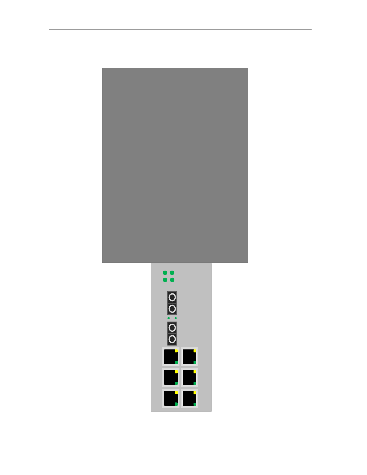
PWR
1 2
3
8
TX
RX
LINK/ACT
10/100M
TX
RX
3
4
6 7
5
RUN
LINK/ACT
2.3 Physical Connections
ESML6-FL2
 Loading...