


Ethernet Switch User Manual
Ethernet Switch
ESML6-FL2-M2
ESML6-FL2-S2
Management Software
User Manual

Ethernet Switch User Manual
TABLE OF CONTENTS
1 OVERVIEW ................................................................................. 4
1.1
I
NTRODUCTION
........................................................................................ 4
2 LOGGING IN ................................................................................ 4
2.1
2.2
2.3
L
OG IN VIA THE CONSOLE PORT – HYPER TERMINAL
L
OG IN USING TELNET
L
OG IN USING A WEB BROWSER
................................................................................ 7
..................................................................... 8
............................................. 4
3 CONSOLE MANAGEMENT USING THE CONSOLE PORT & TELNET ................. 9
3.1
3.1.1
M
AIN MENU
Status and Counters ........................................................................... 10
............................................................................................ 9
1.
2.
3.
3.1.2
1.
2.
3.
4.
5.
6.
7.
3.1.3
1.
2.
Port Status ........................................................................................ 10
Port Counters ..................................................................................... 11
System Information ............................................................................ 11
Switch Static Configuration .................................................................. 12
Administration Configuration ................................................................ 12
Port/Trunk Configuration ..................................................................... 15
Port Mirroring Configuration ................................................................. 15
VLAN Configuration ............................................................................. 16
Priority Configuration .......................................................................... 19
MAC Address Configuration .................................................................. 19
Misc Configuration .............................................................................. 22
Protocol Related Configuration.............................................................. 24
STP/ Spanning Tree Protocol ................................................................ 25
SNMP ................................................................................................ 27
3.
4.
3.1.4
1.
Manual_sw-ESML6-FL2-Rev1106
Copyright © KBC Networks Ltd. Page 1 of 64 www.kbcnetworks.com
GVRP ................................................................................................ 30
LACP ................................................................................................. 30
Reboot Switch .................................................................................... 32
Default .............................................................................................. 32

Ethernet Switch User Manual
2.
Restart .............................................................................................. 32
4 CONSOLE INTERFACE COMMANDS ................................................... 33
4.1
4.2
4.3
4.4
4.5
4.6
4.7
4.8
4.9
4.10
C
OMMAND LINE
C
OMMANDS FOR THE SYSTEM CONFIGURATION
C
ONFIGURING THE SWITCH - ADVANCED CONFIGURATIONS
C
OMMANDS FOR PORT CONTROL
C
OMMANDS FOR LINK AGGREGATION
C
OMMANDS FOR
C
OMMANDS FOR
C
OMMANDS FOR SPANNING TREE PROTOCOL
C
OMMANDS FOR THE PORT SNIFFER
T
ABLE
A .............................................................................................. 40
..................................................................................... 33
................................................. 33
.................................. 34
.................................................................. 35
............................................................ 36
IGMP S
VLAN ............................................................................. 38
NOOPING
............................................................... 37
................................................... 39
.............................................................. 39
5 CONSOLE MANAGEMENT USING A WEB INTERFACE ............................... 41
5.1
5.1.1
5.1.2
5.1.3
1.
2.
3.
4.
5.
6.
7.
8.
M
AIN MENU
Port Status ........................................................................................ 41
Port Statistics ..................................................................................... 42
Administrator ..................................................................................... 42
IP Address ......................................................................................... 42
Configuration ..................................................................................... 43
Other Configurations ........................................................................... 44
Priority Queue Service ......................................................................... 44
Protocol Configuration ......................................................................... 45
Console Info ...................................................................................... 45
Port Control ....................................................................................... 46
Aggregator ........................................................................................ 46
.......................................................................................... 41
9.
10.
11.
12.
Manual_sw-ESML6-FL2-Rev1106
Copyright © KBC Networks Ltd. Page 2 of 64 www.kbcnetworks.com
Filter ................................................................................................. 48
VLAN Config ....................................................................................... 51
Spanning Tree Protocol (STP) ............................................................... 53
Analysis Port ...................................................................................... 55

Ethernet Switch User Manual
13.
14.
5.1.4
1.
2.
5.1.5
5.1.6
SNMP ................................................................................................ 56
Security Management.......................................................................... 57
Configuration Backup .......................................................................... 57
TFTP Restore Configuration .................................................................. 57
TFTP Backup Configurations ................................................................. 58
Reset System ..................................................................................... 58
Reboot .............................................................................................. 62
Manual_sw-ESML6-FL2-Rev1106
Copyright © KBC Networks Ltd. Page 3 of 64 www.kbcnetworks.com
Ethernet Switch User Manual
Fig 2
-
1 Log in Via Console Management
1 Overview
1.1 Introduction
This manual covers the ESML6-FL2 series management software. This software supports
Telnet, SNMP protocols and is compliant with networking regulations. This switch can be
managed and monitored using third party software. Configuration of the switch,
monitoring and other network management features can be achieved in 3 ways:
• via the console port (HyperTerminal)
• using Telnet
• using a web browser
2 Logging in
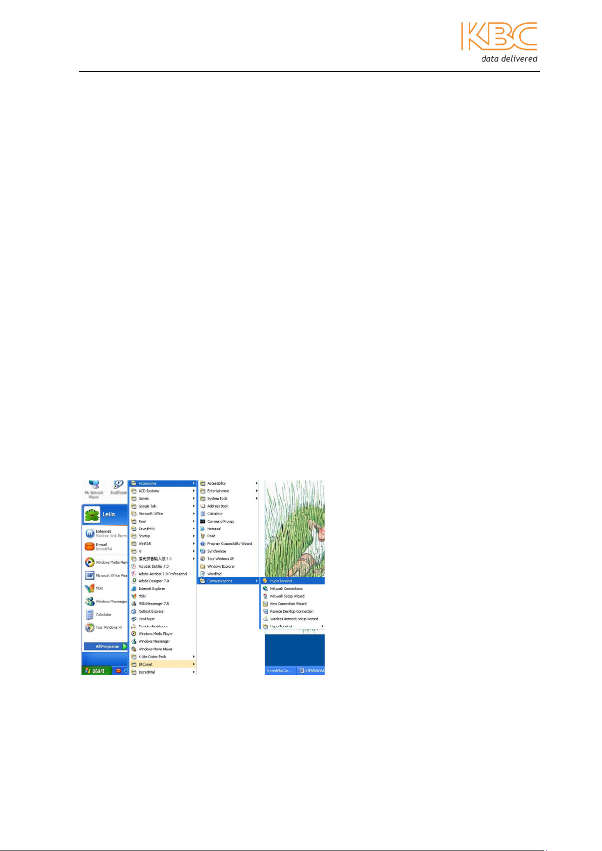
2.1 Log in via the Console Port – Hyper Terminal
The Hyper Terminal in Microsoft Windows can be used to log into the switch management
software. If there is no Hyper Terminal, the user can install it in Windows. After finishing
installation, access the RS232 console software as follows:
• Connect the RS232 console port of the ESML6-FL2 to the serial port of a computer
using the console cable provided.
• In Windows, start Hyper Terminal as shown below in Fig 2-1:
Manual_sw-ESML6-FL2-Rev1106
Copyright © KBC Networks Ltd. Page 4 of 64 www.kbcnetworks.com
Ethernet Switch User Manual
Fig 2
-
4 Configure Serial Port
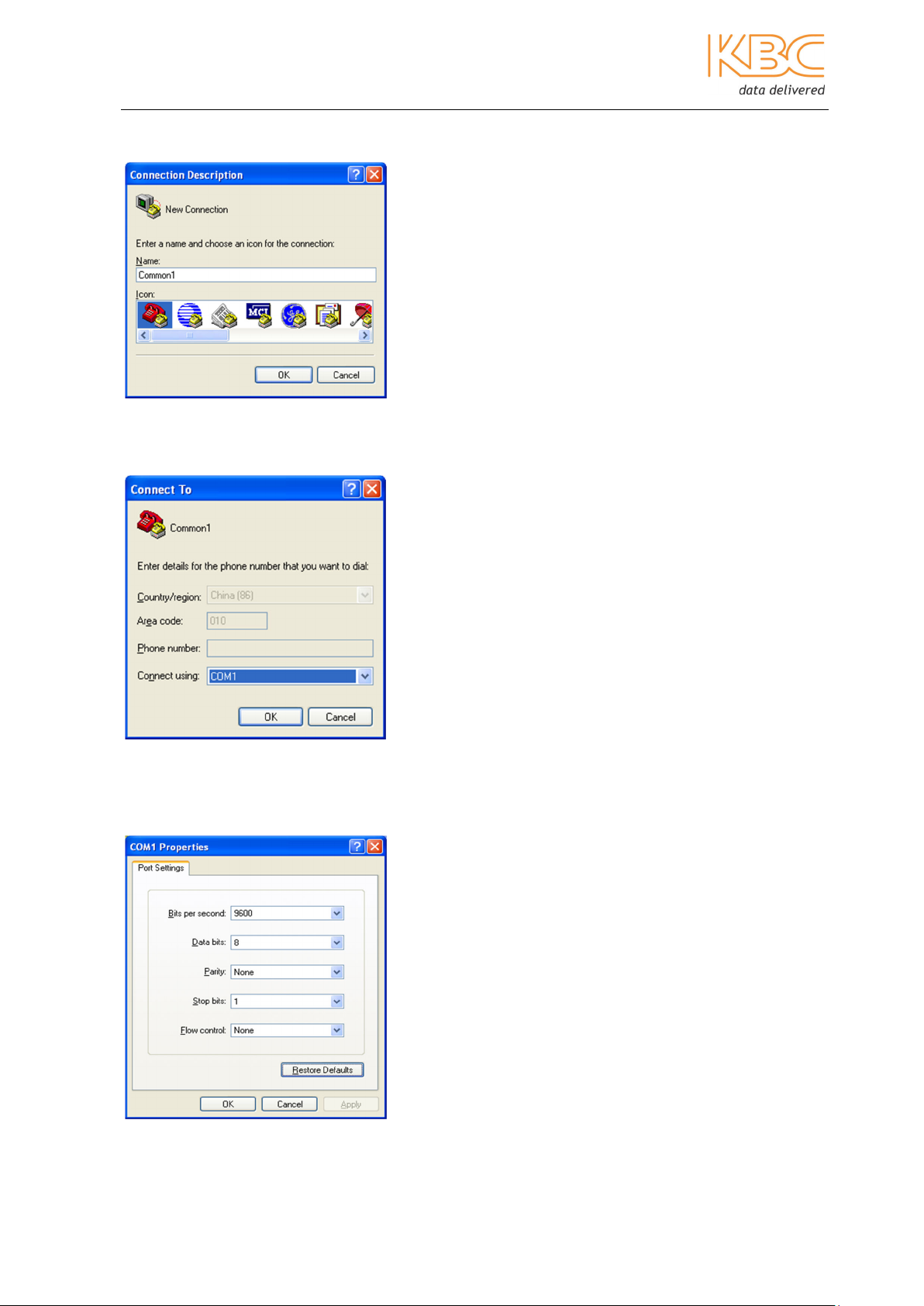
You will be prompted to enter a new link name eg. “Common1” as shown below:
Fig 2-2 Establish a Link
1. Select a serial port and click on the “OK” button as shown in Fig 2-3:
Fig 2-3 Select Serial Port
2. Configure port “COM1” as shown below in Fig 2-4. Click on the “OK” button to
move to the user interface.
Manual_sw-ESML6-FL2-Rev1106
Copyright © KBC Networks Ltd. Page 5 of 64 www.kbcnetworks.com
Ethernet Switch User Manual
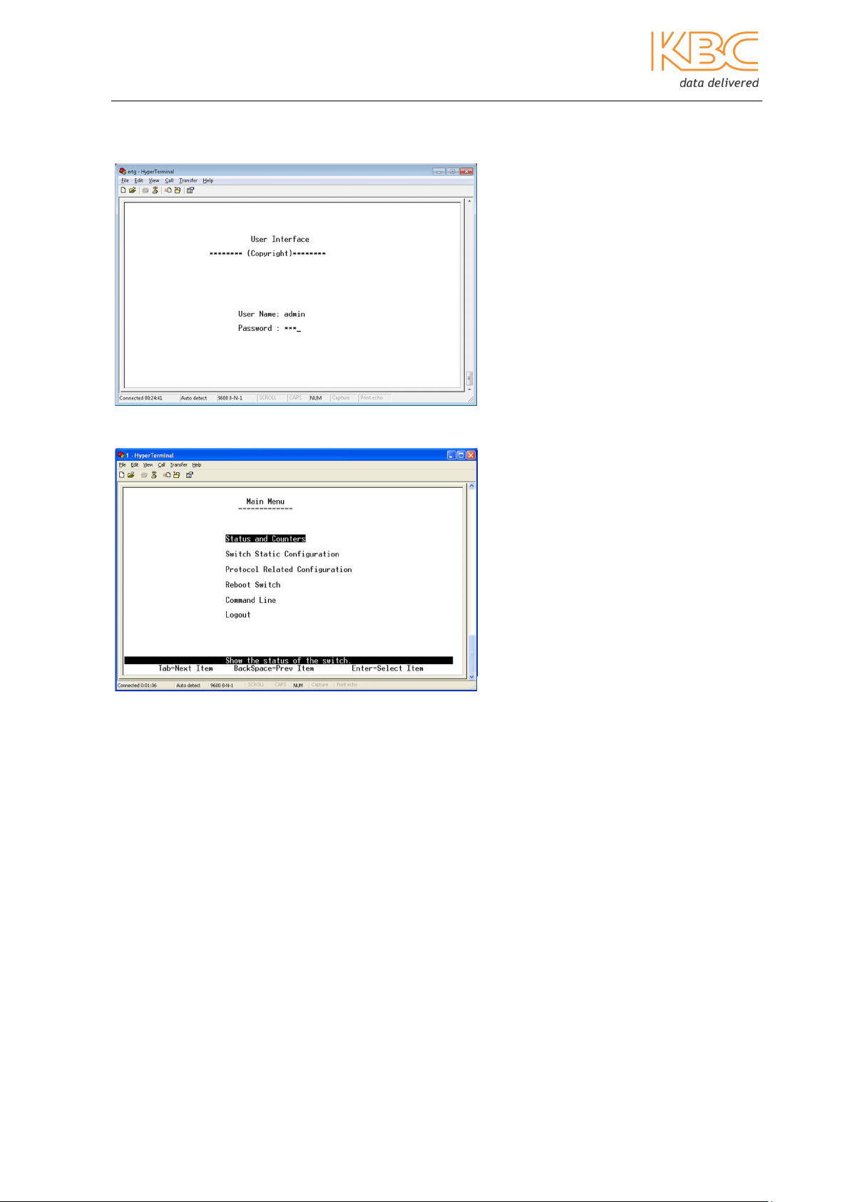
3. In the user interface screen, enter the default user name “admin” and password
“123” and press the enter key, the user will be presented with the main menu.
Fig 2-5 User Interface
Fig 2-6 Main Menu
Manual_sw-ESML6-FL2-Rev1106
Copyright © KBC Networks Ltd. Page 6 of 64 www.kbcnetworks.com
Ethernet Switch User Manual
2.2 Log in using Telnet
The user can also use Telnet to log into the switch management software. Use a crossover or straight-through cable to attach an RJ45 port of the switch to the RJ45 port of a
PC. Access as follows:
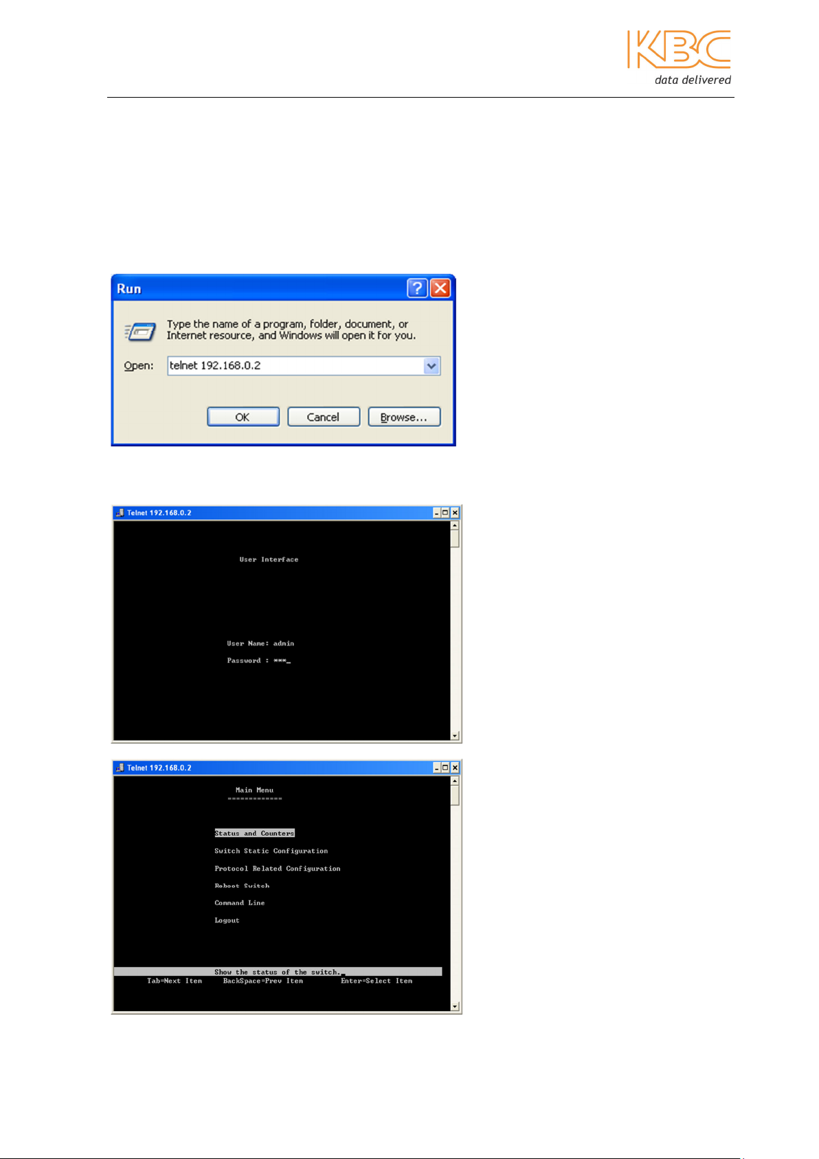
1. In the “Run” page in Windows, enter “telnet 192.168.0.2” and click on “OK” as shown
in Fig 2-7:
Fig 2-7 Run Telnet Commands
2. Enter the user name: “admin” and password: “123” and press the ‘OK’ key to
access the main menu of the Telnet console management as shown Fig 2-8:
Fig 2-8 Log in to Telnet Console
Fig 2-9 Main Menu of Telnet Console
Manual_sw-ESML6-FL2-Rev1106
Copyright © KBC Networks Ltd. Page 7 of 64 www.kbcnetworks.com
Ethernet Switch User Manual
2.3 Log in using a web browser
To access the switch via a web browser, the switch needs to be connected from one of its
RJ45 ports by a straight-through cable to the computer. The user can view or modify the
IP address once in the management software.
MAC address: 000060006000
IP address: 192.168.0.2
Subnet mask: 255.255.255.0
Default gateway: 192.168.0.1
Access the web in the following way:
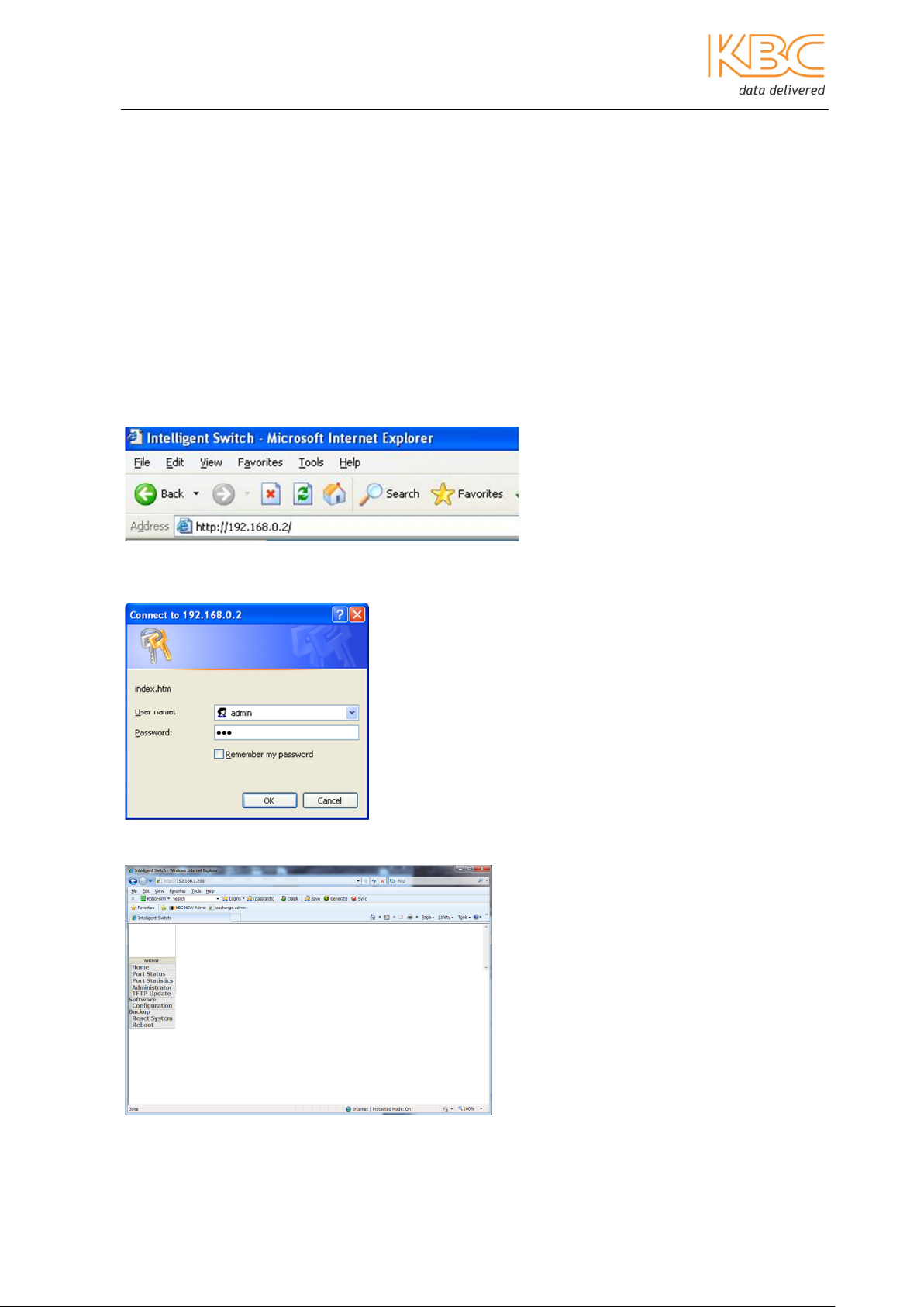
1. Start a web browser and enter the appropriate IP address, press the enter key to
open the connection as shown in Fig 2-10:
Fig 2-10 Start Web Management
2. Enter the user name “admin” and password “123” in the presented page and
click on the “Log in” button.
Fig 2-11 Log in to the Web Interface
3. The main web page will be displayed as below:
Fig 2-12 Main Web Page
Manual_sw-ESML6-FL2-Rev1106
Copyright © KBC Networks Ltd. Page 8 of 64 www.kbcnetworks.com
Ethernet Switch User Manual
3 Console Management using the Console
Port & Telnet
3.1 Main Menu
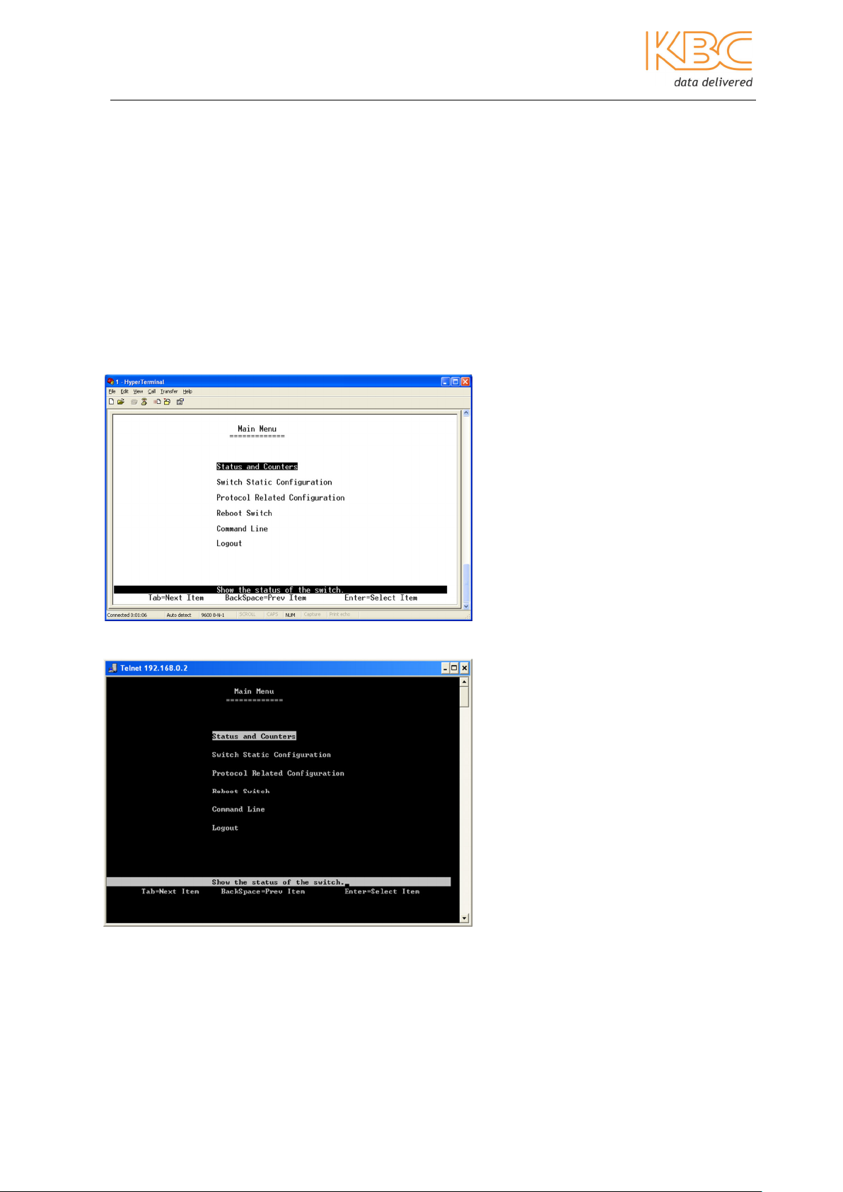
Menu options and functions through the console port and Telnet are identical see Fig 3-1.
Once in the main menu, as shown below, use the keys in Table 3-1 to navigate the
system. Within the main menu there are 6 options.
Fig 3-1 Main Menus
Manual_sw-ESML6-FL2-Rev1106
Copyright © KBC Networks Ltd. Page 9 of 64 www.kbcnetworks.com
Ethernet Switch User Manual
Key Function
<Tab>:
<Backspace>:
<Enter>:
<Space>:
<Ctrl+A>:
switch to next sub-menu
switch to the previous sub-menu
select the desired sub-menu
make configuration changes
apply the current item
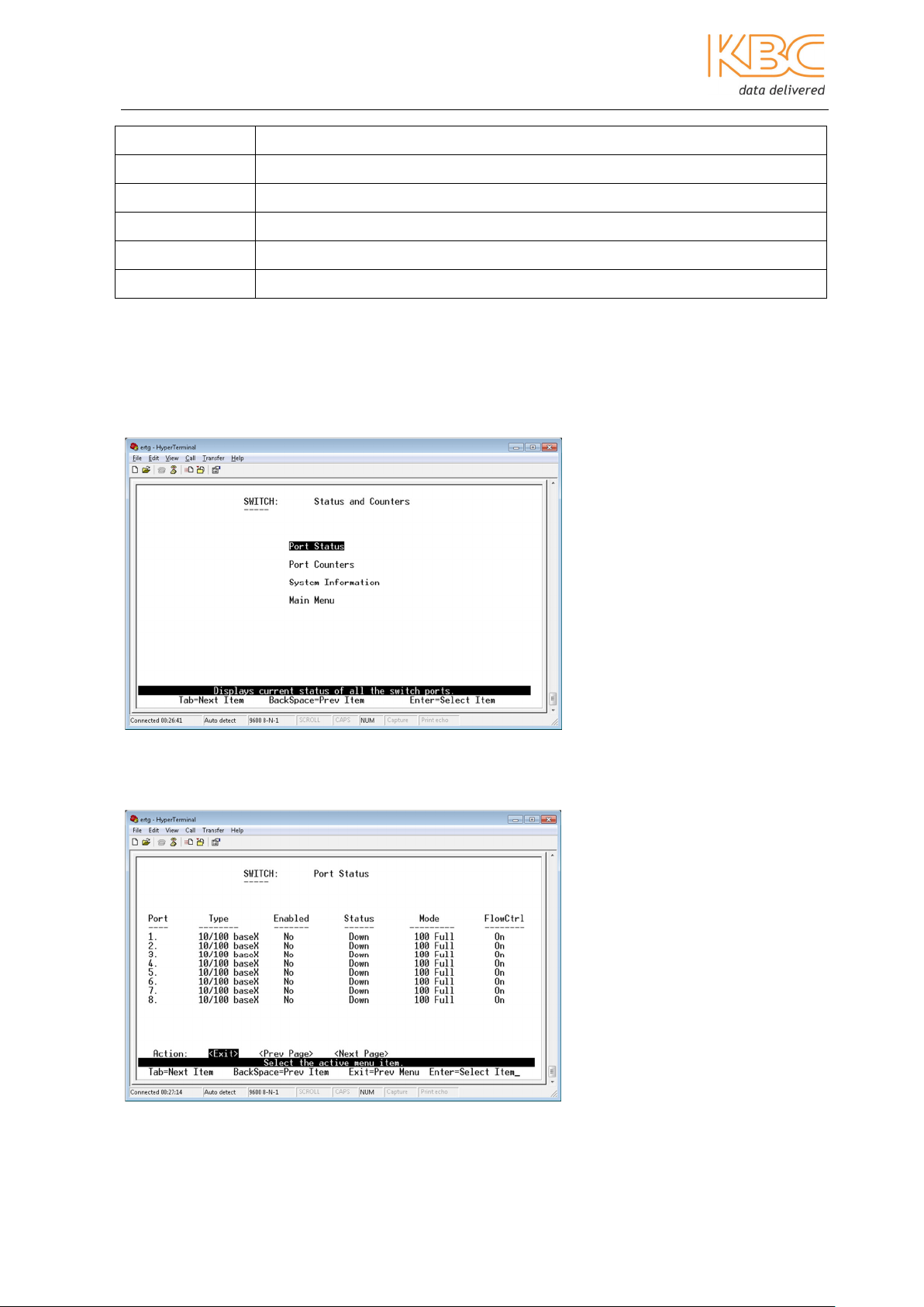
3.1.1 Status and Counters
Within the Status and Counters menu option there are 3 sub-menus:
Table 3-1 Commands
1. Port Status
Displays the status of each port:
Fig 3-2 Status and Counters
Fig 3-3 Port Status
Manual_sw-ESML6-FL2-Rev1106
Copyright © KBC Networks Ltd. Page 10 of 64 www.kbcnetworks.com
Ethernet Switch User Manual
Item Description
Type Port type
Enable Indicates whether the port is enabled or not
Status Indicates if the port is linked or not linked
Mode Indicates the port rate and transmission mode
Flow Control Indicates if flow control is enabled or not
Table 3-2 Port Status Display
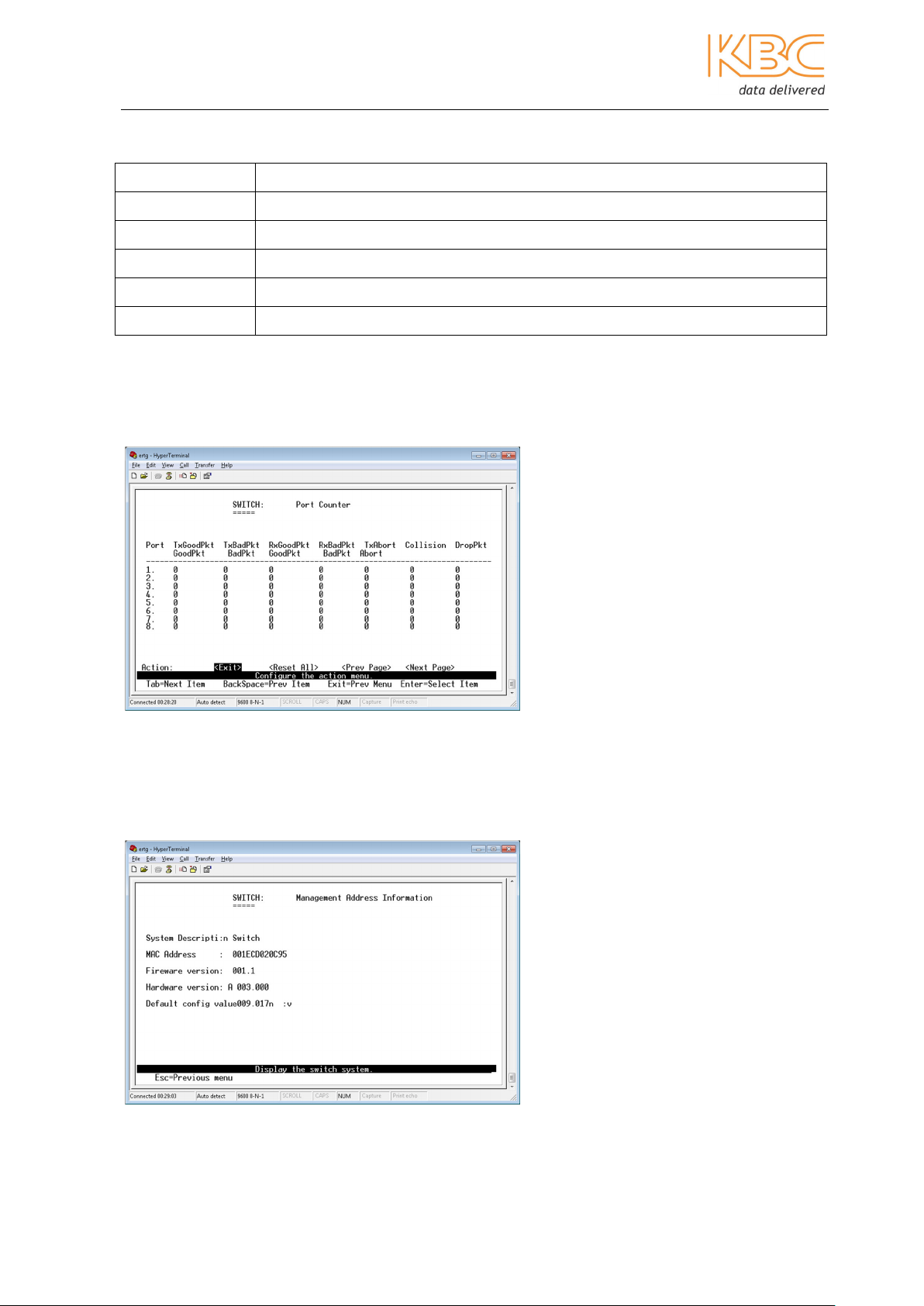
2. Port Counters
Displays the communication state of the device.
Fig 3-4 Port Counters
3. System Information
Displays information about the hardware and software of the device.
Fig 3-5 System Information
Manual_sw-ESML6-FL2-Rev1106
Copyright © KBC Networks Ltd. Page 11 of 64 www.kbcnetworks.com
Ethernet Switch User Manual
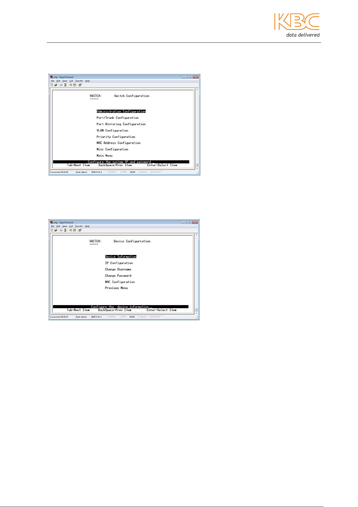
3.1.2 Switch Static Configuration
Within the ‘Switch Static Configuration’ menu option there are 7 sub-menus:
Fig 3-6 Switch Configuration
1. Administration Configuration
Within this menu option there are a further 5 sub-menus.
Fig 3-7 Administration Configuration
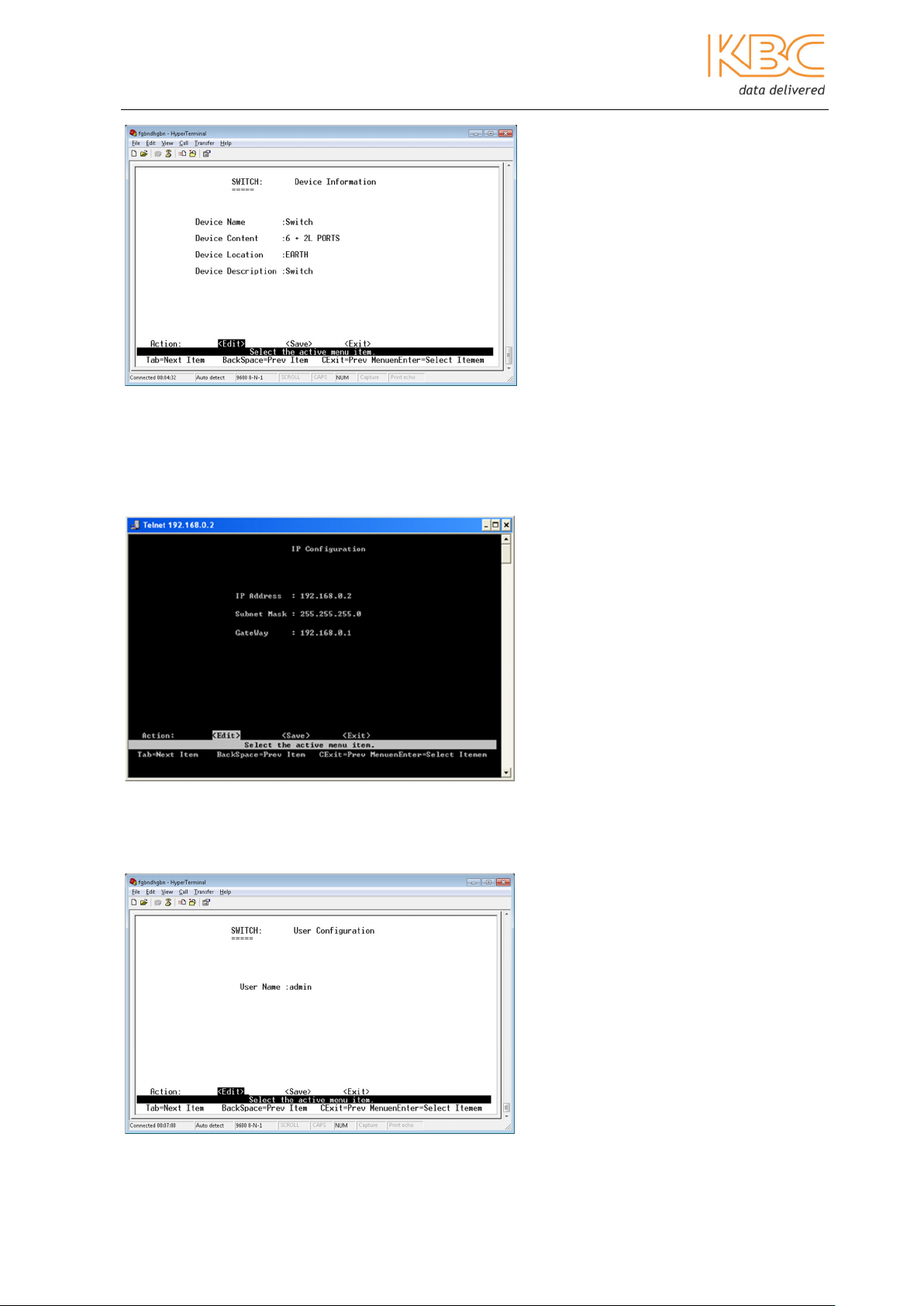
a) Device Information
This allows the user to configure the device information including name, device
specifications, device location & device description.
Manual_sw-ESML6-FL2-Rev1106
Copyright © KBC Networks Ltd. Page 12 of 64 www.kbcnetworks.com
Ethernet Switch User Manual
Fig 3-8 Device Information
b) IP Configuration
This allows the user to configure the IP address, subnet mask and gateway.
Fig 3-9 IP Configuration
c) Change Username
This menu option is used to change the user name.
Fig 3-10 Change Username
Manual_sw-ESML6-FL2-Rev1106
Copyright © KBC Networks Ltd. Page 13 of 64 www.kbcnetworks.com
Ethernet Switch User Manual
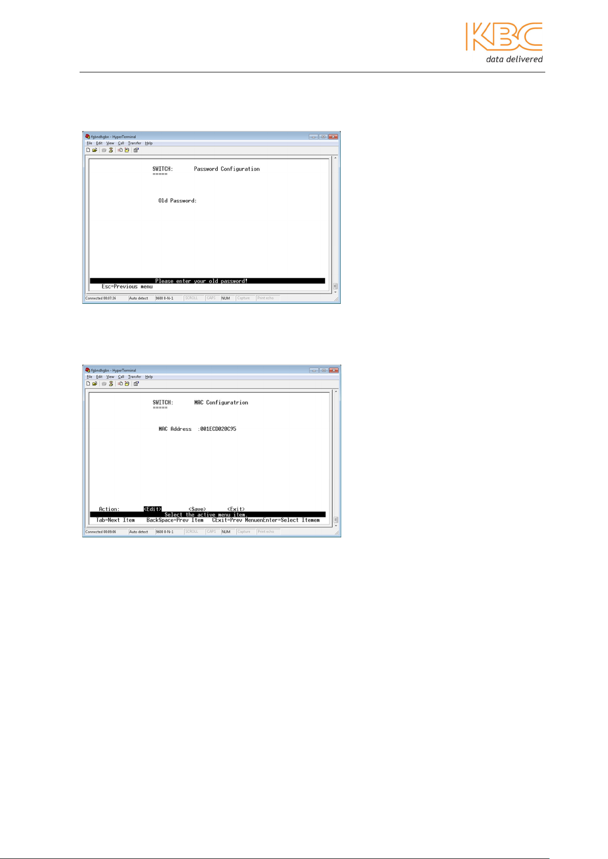
d) Change password
This page is used to change the administration password.
Fig 3-11 Change Password
e) MAC Configuration
The user can configure the MAC address of the switch; this is not recommended as it
could potentially cause conflicts among the other switches in the network.
Fig 3-12 MAC Configuration
Manual_sw-ESML6-FL2-Rev1106
Copyright © KBC Networks Ltd. Page 14 of 64 www.kbcnetworks.com
Ethernet Switch User Manual
Item
Description
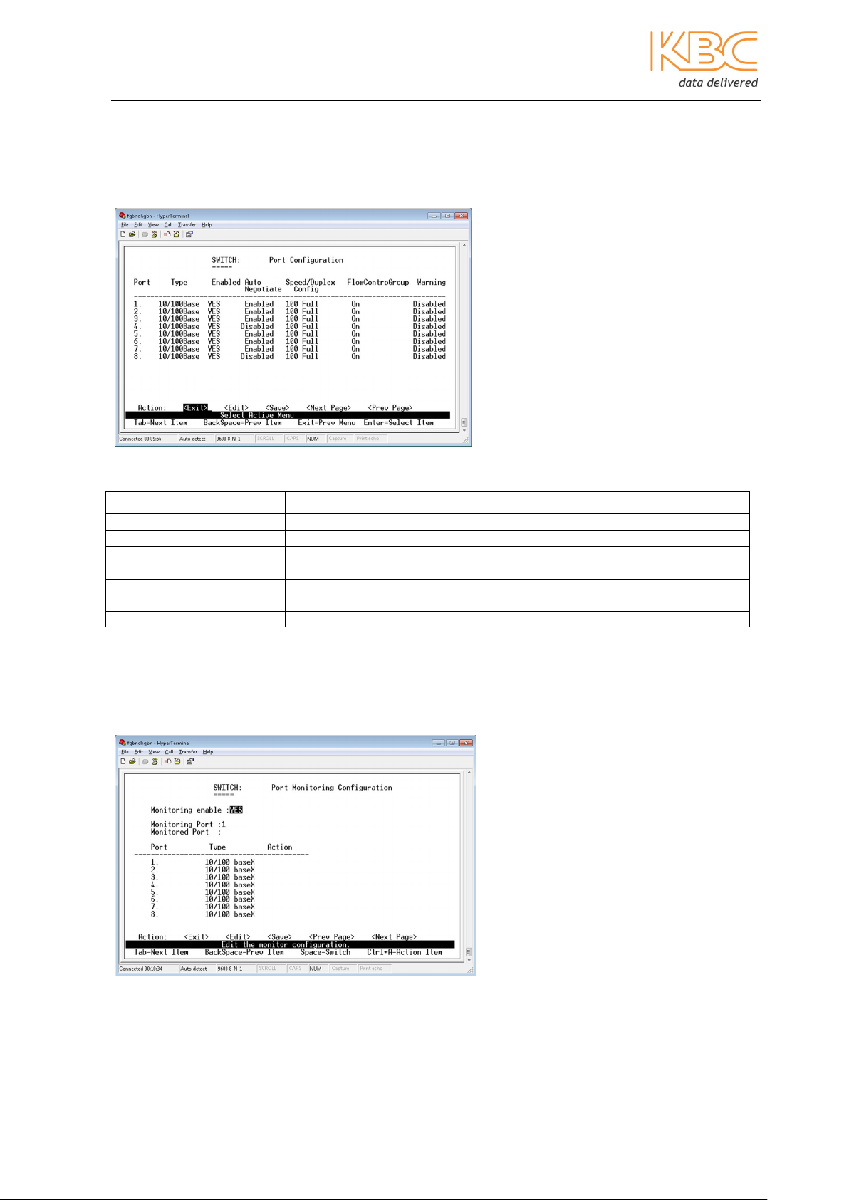
2. Port/Trunk Configuration
This menu option is used to modify each port’s status and configure the link aggregation
groups. The user can switch to other data items with the space key. The descriptions of
each configuration are as shown in Table 3-2.
Fig 3-13 Port / Trunk Configuration
Enable
Auto-negotiation
Port rate/transmission
Flow control
Group
Alarm Enable or disable the alarm function of the port
Enable or disable the port
To enable or disable the auto-negotiation function of each port
Set the port rate to 10Mbps or 100Mbps, half or full duplex
Enable or disable the flow control function
Configure the link aggregation group. There are 4 groups that can be
configured.
Table 3-2 Port aggregation/alarm configuration
3. Port Mirroring Configuration
Port mirroring is used to monitor the network traffic of one port via another selected
port. The descriptions of each configuration are as shown in Table 3-4:
Fig 3-14 Port Mirroring Configuration
Manual_sw-ESML6-FL2-Rev1106
Copyright © KBC Networks Ltd. Page 15 of 64 www.kbcnetworks.com
Ethernet Switch User Manual
Item
Description
Monitoring
Monitoring Port
Action
Enable or disable port mirroring
The port used to monitor the communication of all ports.
Ports to be monitored. The flow of all monitored ports is copied to the
sniffer port. You can select up to 7 monitored ports in the switch.
From the Action item, you can choose to monitor the receiving frame,
transmitting frame or both.
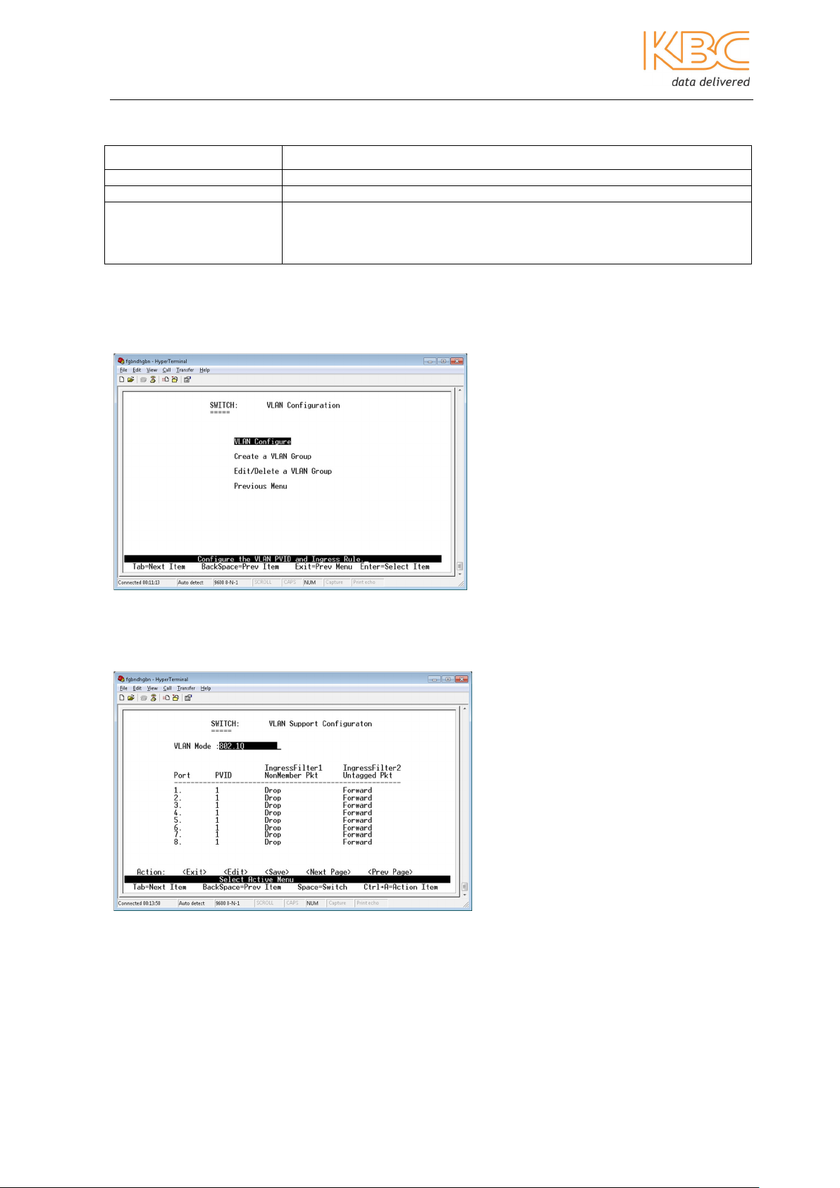
4. VLAN Configuration
Within this option there are 3 further sub-menus.
Table 3-4 Port Mirroring Configuration
Fig 3-15 VLAN Configuration
a) VLAN Configure
This menu option is used to configure the VLAN parameters of each port.
Fig 3-16 VLAN Support Configuration
802.1Q
Manual_sw-ESML6-FL2-Rev1106
Copyright © KBC Networks Ltd. Page 16 of 64 www.kbcnetworks.com
Ethernet Switch User Manual
Item
Description
Item Description
VLAN Mode
PVID
Ingress rule 1
(if frame is not a
member )
Ingress rule 2
(if frame is
untagged)
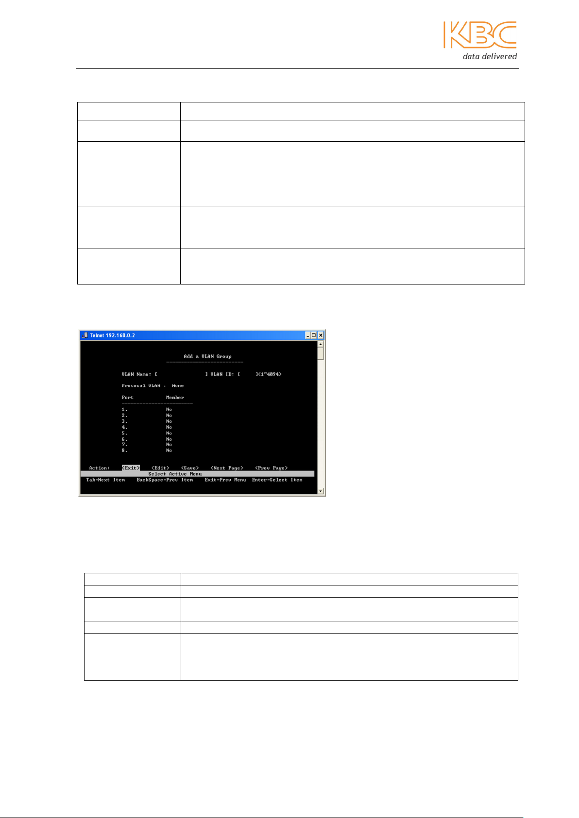
b) Add a VLAN Group
Select the ways to create VLANs based on port, 802.1Q with GVRP and
802.1Q without GVRP.
To specify the VLAN ID associated with untagged frames on the port. Eg. if
the default PVID of port 3 is 100, all untagged frames on port 3 are
associated with VLAN100. The default PVID of all ports is 1. When the user
wants to configure the devices which don’t support tagging and add them
to a VLAN, this feature is used. Only one untagged VLAN is permitted for
each port.
This rule is corresponding to the ingress rule 1 of web management: only
forward the frames with the appropriate VID to the port. With the space
key, the user chooses to forward or drop the frames that have no
appropriate VID.
This rule is corresponding to the ingress rule 1 of web management: drop
the untagged frames. With the space key, the user chooses to forward or
drop the untagged frames.
Table 3-5 VLAN Descriptions
Fig 3-17 Create a VLAN Group
From this option, the user can create a VLAN and add tagged/untagged members to it.
The specific descriptions of each item are shown in Table 2-6:
VLAN Name Enter new VLAN name
VLAN ID Enter number to identify the VLAN group from 2-4094, the default value
is 1.
VLAN Protocol Press the space key to select protocol.
Press the space key to select VLAN members including 3 types:
Members
Tagged: the port is tagged member.
Untagged: the port is untagged member.
None: the port is not the member of the VLAN.
Table 3-6 VLAN Terms
Manual_sw-ESML6-FL2-Rev1106
Copyright © KBC Networks Ltd. Page 17 of 64 www.kbcnetworks.com
Ethernet Switch User Manual
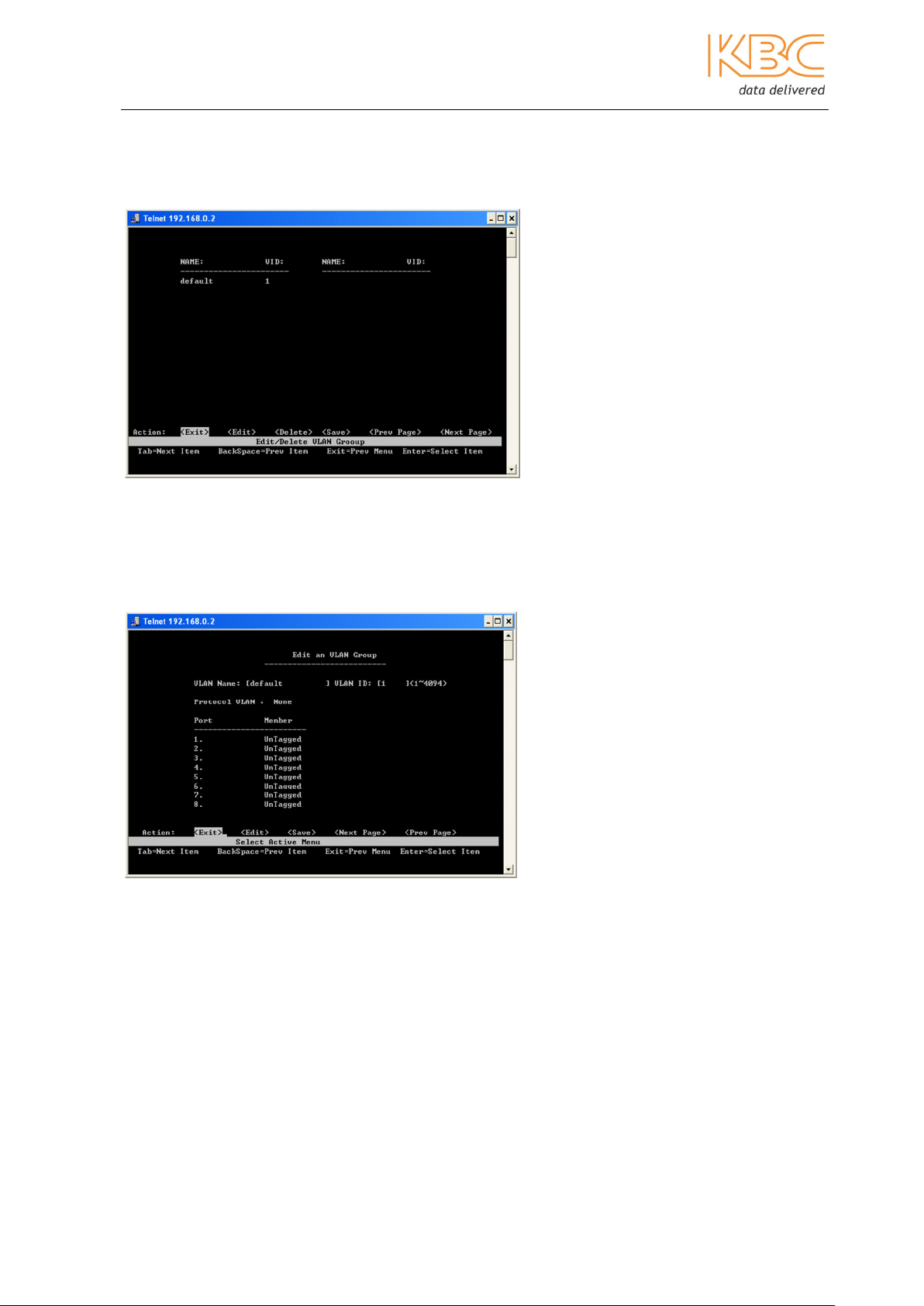
Fig 3
-
19 Edit a
VLAN
Group
c) Edit/Delete a VLAN Group
From this page, the user can edit or delete the VLAN. The VLAN name and VLAN ID
cannot be changed. The default VLAN cannot be deleted.
Fig 3-18 Edit / Delete a VLAN Group
• Select the desired VLAN, press <Enter>.
• Change the VLAN protocol, set the member port as tagged or untagged or delete
the member port in VLAN group as required.
• Select <Save> to save all configurations.
Manual_sw-ESML6-FL2-Rev1106
Copyright © KBC Networks Ltd. Page 18 of 64 www.kbcnetworks.com
Ethernet Switch User Manual
Fig 3
-
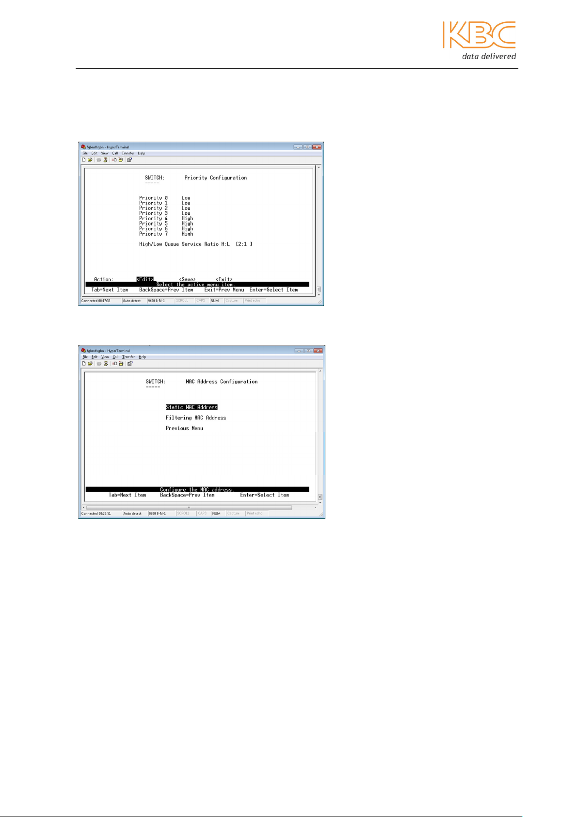
20 Priority Configuration
5. Priority Configuration
This menu option allows the user to choose a priority class from 0 to 7, (0 being lowest
and 7 being highest). It is used to specify the weighting algorithm for transmitting
different priority frames.
6. MAC Address Configuration
In this menu option there are 2 sub-menus:
Fig 3-21 MAC Address Configuration
Manual_sw-ESML6-FL2-Rev1106
Copyright © KBC Networks Ltd. Page 19 of 64 www.kbcnetworks.com

Ethernet Switch User Manual
a) Static MAC Address
From this page, the user can add, edit or delete the static MAC address.
Fig 3-22 Static MAC Address
When a static MAC address is added, no matter whether the physical device is connected
to the switch or not, the address will be kept in the switch’s address table. The switch
does not need to learn the MAC address of the device again if the networking device is
re-connected after power off or disconnection.
<Add> - Add a static MAC address
• Select <Add> then in the next screen select <Edit> to add a static MAC address.
• Enter the MAC address, whose frames will be always forwarded by the switch’s
port regardless of the networking status.
• Enter the port number.
• If the IEEE802.1Q VLAN is set in the switch, the static MAC address must be
associated with the unique VLAN. Enter the VID appropriate to the MAC address.
• Select <Save> and press <Enter> to save all changes.
• <Ctrl + A> will return you to the main menu.
<Edit> - Edit a static MAC address
• Select <Edit> and press the enter key to modify the static MAC address.
• Select the desired MAC address and press <Enter>.
• Select <Edit> and press <Enter> to be able to modify any items.
• Select <Save> and press <Enter> to save all changes.
• <Ctrl + A> will return you to the main menu.
<Delete> - Delete a static MAC address
• Select <Delete> to delete a static MAC address.
• Select the desired MAC address and press <Enter> key.
• Select <Save> and press <Enter> to save all changes.
• <Ctrl + A> will return you to the main menu.
Manual_sw-ESML6-FL2-Rev1106
Copyright © KBC Networks Ltd. Page 20 of 64 www.kbcnetworks.com

Ethernet Switch User Manual
a) Filtering MAC Address
By MAC address filtering, the switch can discard undesired frames. The filtered frames
are based on the destination addresses. The user can add, edit or delete MAC address
from this page.
Fig 3-23 Filtering MAC Address
<Add> - Add a filtered MAC address
• Select <Add> then <Edit> and press <Enter> to add a MAC address.
• Enter the MAC address to be filtered.
• Enter the VID associated with the MAC address if there is IEEE802.1Q VLAN in the
switch.
• Select <Save> and press <Enter> to save all changes.
• <Ctrl + A> will return you to the main menu.
<Edit> - Edit a filtered MAC address
• Select <Edit> and press <Enter>.
• Select the desired MAC address and press <Enter>.
• Select <Edit> and press <Enter> to modify all items.
• Select <Save> to save all changes.
• <Ctrl + A> will return you to the main menu.
<Delete> - Delete a filtered MAC address
• Select <Delete> and press <Enter>.
• Select the desired MAC address and press <Enter>.
• Select <Save> to save all changes.
• <Ctrl + A> will return you to the main menu
Manual_sw-ESML6-FL2-Rev1106
Copyright © KBC Networks Ltd. Page 21 of 64 www.kbcnetworks.com

Ethernet Switch User Manual
7. Misc Configuration
In this menu option there are 4 sub-menus.
Fig 3-24 Misc Configuration
a) Port Security
If the security feature is enabled, the port will not learn any MAC addresses and only the
received frames with the static MAC address existing in the table will be forwarded
normally. This prevents the access of illegal terminal devices.
Fig 3-25 Port Security
Manual_sw-ESML6-FL2-Rev1106
Copyright © KBC Networks Ltd. Page 22 of 64 www.kbcnetworks.com

Ethernet Switch User Manual
b) MAC Age Interval
This feature is used to specify the time to keep an inactive MAC address in the switch
address table. The valid range of time is 300-765 seconds. The default value is 300
seconds.
Fig 3-26 MAC Age Interval
c) Broadcast Storm Filtering
This feature is used to configure the broadcasting storm control. When this feature is
enabled the threshold value can be set for the port. The threshold value set is the
percentage of the bandwidth of the broadcasting flow for the port. When the threshold
value is exceeded the control becomes enabled. The options are: 5%,10%,15%,
20%,25%.
To set the desired values select <Edit> and press the enter key to configure the filtering
mode. Press the space key to select the value.
Fig 3-27 Broadcast Storm Filtering
Manual_sw-ESML6-FL2-Rev1106
Copyright © KBC Networks Ltd. Page 23 of 64 www.kbcnetworks.com

Ethernet Switch User Manual
Item
Description
d) Max bridge transmit delay
Fig 3-28 Max Bridge Transmit Delay
Max Bridge
Transmission
Delay
Enable Delay
Bound
Max Delay
Time
The max queuing time of frames in the switch. If enabled, a frame whose
queuing time exceeds the limit will be dropped.
This sets whether the limit of queuing time for low-priority frames is enabled or
disabled. If the queuing time exceeds the limit (see Max Delay Time below) the
low-priority frames will be transmitted.
The queuing time of the low-priority frames in the switch. The default latency
time 255ms. The valid range is 0-255ms.
3.1.3 Protocol Related Configuration
This menu options has 4 sub-menu options.
Table 3-7 Max Bridge Transmit Delay
Fig 3-29 Protocol Related Configuration
Manual_sw-ESML6-FL2-Rev1106
Copyright © KBC Networks Ltd. Page 24 of 64 www.kbcnetworks.com

Ethernet Switch User Manual
1. STP/ Spanning Tree Protocol
There are three further sub-menus within this menu option.
Note: If DT-Ring is being used in a KBC switch network STP should not be enabled.
Fig 3-30 STP/Spanning Tree Protocol
a) STP Enable
This menu option is used to enable or disable the Spanning Tree feature. Press the space
key to enable or disable this feature.
Fig 3-31 STP Enable
Manual_sw-ESML6-FL2-Rev1106
Copyright © KBC Networks Ltd. Page 25 of 64 www.kbcnetworks.com

Ethernet Switch User Manual
Item
Description
b) System Configuration
The bridge STP parameters are displayed on the left of the page. The user can set new
STP parameters on the right. For more detailed descriptions of the settings refer to
Chapter 5.
Fig 3-32 STP System Configuration
c) Perport Configuration
The parameters of each port are shown in Table 3-7:
Fig 3-33 Per Port Configuration
Port Status Shows the Spanning Tree status of each port
The path cost of designated port. The port with the lowest path cost is used to
Path Cost
Priority
forward data. The value range of the path cost is 1~ 65535. The default values of
IEEE802.1D specifications are 10Mb/s = 50-600;100Mb/s = 10-60;1000Mb/s =
3-10. Any changes to the values require the switch to be reset.
By this value, the port can be set as the root port. The value range is 0 ~ 255,
the default value is 128. The smaller value, the higher priority. To change the
value, the switch must be reset.
Table 3-7 Port Parameters
Manual_sw-ESML6-FL2-Rev1106
Copyright © KBC Networks Ltd. Page 26 of 64 www.kbcnetworks.com

Ethernet Switch User Manual
Item
Description
2. SNMP
There are three sub-menus within this menu option.
Fig 3-34 SNMP
a) System Options
System Name enter the switch name
System Contact enter the user name or group name to which the switch belongs
System Location enter the installation position of the switch
Table 3-8
Fig 3-35 System Item Configuration
Manual_sw-ESML6-FL2-Rev1106
Copyright © KBC Networks Ltd. Page 27 of 64 www.kbcnetworks.com

Ethernet Switch User Manual
Item
Description
b) Community Strings
This page is used to configure the group strings. Use <Add> and <Edit> to change
settings.
Fig 3-36 SNMP Community
Configuration
Group name enter the name of the group string
Restricted: read only, enables the request to display the MIB object information
Write Access
Unrestricted: read-write, enables the request to display the MIB object
information and configure the MIB object
Table 3-9 Add/Edit Strings
Fig 3-37 Edit SNMP Community
Manual_sw-ESML6-FL2-Rev1106
Copyright © KBC Networks Ltd. Page 28 of 64 www.kbcnetworks.com

Ethernet Switch User Manual
c) Trap Managers
The trap manager is the host station that receives traps. The trap is generated by the
alarm system of the switch. If no trap manager is defined, there will be no traps sent. To
create a new trap manager enter an IP address and a group name. Use <Add> and
<Edit> to change settings.
Fig 3-38 Trap Managers Configuration
Fig 3-39 Add SNMP Trap Manager
Manual_sw-ESML6-FL2-Rev1106
Copyright © KBC Networks Ltd. Page 29 of 64 www.kbcnetworks.com

Ethernet Switch User Manual
3. GVRP
This menu option is used to enable or disable the GVRP (GARP VLAN Registration
Protocol feature).
Fig 3-40 GVRP Configuration
4. LACP
This menu options contains three sub-menus:
Fig 3-41 LACP
Manual_sw-ESML6-FL2-Rev1106
Copyright © KBC Networks Ltd. Page 30 of 64 www.kbcnetworks.com

Ethernet Switch User Manual
Group
D
isplay
s the group ID
Enabled or disabled.
If enabled, the group is
a
LACP s
t
atic trunking
The max number of ag
gregated ports. If it is
a
static LACP trunking
a) Aggregator Setting
Note: Before configuring LACP, first configure the trunking group in the Port/Trunk
configuration menu.
Fig 3-42 LACP Group Configuration
Item
Description
LACP
LACP Port
Number
group.
group, the extra port is used as backup for the failure. If it is local static
trunking group, the port number must be identical to the trunk ports.
b) State Activity
Table 3-10 LACP Descriptions
Fig 3-43 State Activity
Select <Edit> and press <Enter>, then use the space key to edit the properties of each
port.
The passive end: the ports won’t send the LACP frames automatically, the port will
respond only after it receives frames from the corresponding switch.
The active end: the ports will send the LACP frames automatically.
Manual_sw-ESML6-FL2-Rev1106
Copyright © KBC Networks Ltd. Page 31 of 64 www.kbcnetworks.com

Ethernet Switch User Manual
c) LACP Status
Fig 3-44 LACP Status
3.1.4 Reboot Switch
Fig 3-45 Restart Configuration
1. Default
Select the default option to reset the switch configuration to the factory settings. The
detailed defaults are shown on Page 52.
2. Restart
Select restart to reboot the switch.
Manual_sw-ESML6-FL2-Rev1106
Copyright © KBC Networks Ltd. Page 32 of 64 www.kbcnetworks.com

Ethernet Switch User Manual
4 Console Interface Commands
4.1 Command Line
Switch the command from menu mode to command line.
4.2 Commands for the System Configuration
Command
show ip display the IP address, subnet mask and gateway of the switch.
config ip configure the IP address of the switch.
config subnet configure the subnet mask address of the switch.
config gateway configure the gateway address of the switch.
show mac display the MAC address.
show version display the software version no.
show console display the console info.
config default load the switch defaults.
reboot reboots the switch.
Description
Manual_sw-ESML6-FL2-Rev1106
Copyright © KBC Networks Ltd. Page 33 of 64 www.kbcnetworks.com

Ethernet Switch User Manual
Command
Descriptio
n
4.3 Configuring the Switch - Advanced Configurations
Age-out Time
Enable fdbage enable the MAC address auto aging time feature.
Disable fdbage disable the MAC address auto aging time feature.
Config fdbage<number>
Show fdbage display the aging time.
configure the MAC address auto aging time. The valid value is
300~765 secs
Broadcast Storm Filter
Enable bsf[5|10|15|20|25] enable or configure boadcasting storm filter, eg. enable bsf 10.
Disable bsf disable the broadcasting storm filter.
Show bsf display the configuration of the broadcasting storm filter
Priority Queue Service
configure the priority queue service. The following options can
be specified:
Fcfs: first come first service
Wrr: weighting round robin
Config
qos[fcfs|wrr|strict]<hw:1~7
><lw:1~7>
Strict: higher priority frames are transmitted before lower
priority frames.
<hw>: high weighting priority, the valid value is 1-7. only
effective in WRR.
Eg. Config qos fcfs
Config qos wrr 5 1
Enable qdlyb<1~255>
Disable qdlyb disable the low queue latency threshold value.
Show qos display the queue configurations.
Config qospolicy<high level
list>
To enable lower queue latency threshold values. Values need to
be between 1 & 255ms. Eg. enable qdlyb 200
configure the policy of QoS. The priority of 0 to7 can be
mapped to higher or lower queues
<high level list>: belongs to higher priority with effective
values from 0 to 7
Eg.config qospolicy 0~3
Manual_sw-ESML6-FL2-Rev1106
Copyright © KBC Networks Ltd. Page 34 of 64 www.kbcnetworks.com

Ethernet Switch User Manual
Command
Description
4.4 Commands for Port Control
display the port or ports status
Show portstatus <portlist>
Show statistics <portlist>
Config ports <portlist> state
[off|on]
Config ports <portlist> auto
[off|on]
<portlist>: port number. Eg. show portstatus 1-10
show portstatus 1,3,5
display the port or ports statistics
Eg. show statistics 1-10
show statistics 1,3,5
modify the ports status.
<portlist>: port number
state off: disable the port.
state on: enable the port.
Eg. config ports 1-5 state off
enable or disable port auto-negotiation.
<portlist>: port number.
auto off: disable auto negotiation.
auto on: enable auto negotiation.
Config ports <portlist> ability
[10full|10half|100full|100half]
Config ports <portlist> fctl
[on|off]
Eg. config ports 1-5 auto off
configure port rate and duplex mode.
<portlist>: port number.
Eg. config ports 6,7 ability 10full
enable or disable flow control feature.
<portlist>: port number.
Eg. config ports 1-5 fctl off
Manual_sw-ESML6-FL2-Rev1106
Copyright © KBC Networks Ltd. Page 35 of 64 www.kbcnetworks.com

Ethernet Switch User Manual
Commands
Description
4.5 Commands for Link Aggregation
create trunk.
<groupid>: support 4 groups.
lacp [on|off]: on - the group is LACP static trunking.
off - the group is LACP local trunking.
<number>:to assign the working port of the trunking group.
add trkgrp <groupid> lacp
[on|off] workports <number>
ports <portlist>
config trksyspri <number>
If it is static LACP trunking group, the extra port is used as
backup for a failure.
If it is local static trunking group, the port number must be
identical to the trunk ports.
<portlist>:to assign 1 or more ports to the trunking group.
Eg. add trkgrp 1 lacp on workports 2 ports 1-4, or
add trkgrp 1 lacp off workports 4 ports 1-4
configure the LACP priority number of the switch.
<number>: the valid values are 1 to 65535.
show trkgrp display the info of trunking group
show trkgrpcfg display configuration of trunking group.
enable lacpstate <portlist> configure the port as LACP passive or active port.
disable lacpstate <portlist> set active port as passive port.
show lacpstate display if the port LACP status is passive or active.
Delete a trunking group.
del trkgrp <groupid>
<groupid>: trunking group ID(1-4)
configure the working port of the trunking group - only for
LACP static trunking groups.
config trkgrp <groupid>
workports <number>
enable lacp <groupid:1~4> change local trunking to LACP trunking mode.
disable lacp <groupid:1~4> change LACP trunking to local trunking mode.
add trkgrp <1~4> ports
<portlist:1~8>
<groupid>: the LACP static trunking group ID.
<number>: the port number that can be aggregated
simultaneously.
Add a port to the trunking group.
del trkprt <portlist:1~8> trkgrp
<1~4>
delete a port from the trunking group.
Manual_sw-ESML6-FL2-Rev1106
Copyright © KBC Networks Ltd. Page 36 of 64 www.kbcnetworks.com

Ethernet Switch User Manual
Commands
Description
4.6 Commands for IGMP Snooping
IGMP Snooping
enable igmp enable IGMP feature.
disable igmp disable IGMP feature.
show igmpstate display whether IGMP feature is enabled or disabled.
Port Security
To enable MAC address learning on one or more ports for
port security.
enable security <portlist>
disable security <portlist>
<portlist>:port number
Eg. enable security 1,3
disable MAC address learning on one or more ports for port
security.
<portlist>:port number Eg. disable security 1,3
Static MAC addresses
add fdb <p> mac
<mac_address> vid
<number> port <number>
delete fdb <p> mac
<mac_address> vid
<number> port <number>
clear fdb p clear all static MAC address table.
show fdb p display all static MAC address table.
create static MAC address item
Eg. add fdb p mac 001234567890 vid 1 port 1
delete static MAC address table
Eg. delete fdb p mac 001234567890 vid 1 port 1
MAC Filtering
add fdb <b> mac
<mac_address> vid
<number>
delete fdb <b> mac
<mac_address> vid
<number>
configure unwanted MAC address. The filtered frames
are based on their destination addresses.
Eg.: add fdb b mac 001234567890 vid 1 port 1
delete the MAC address the switch filters.
Eg. delete fdb b mac 001234567890 vid 1 port 1
clear fdb b clear all filtered MAC addresses.
show fdb b display all filtered MAC addresses.
Manual_sw-ESML6-FL2-Rev1106
Copyright © KBC Networks Ltd. Page 37 of 64 www.kbcnetworks.com

Ethernet Switch User Manual
Commands
Description
4.7 Commands for VLAN
create VLAN group.
<name>: the name assigned to the VLAN. The valid strings
are 15 max.
add vlan <name> vid <number
1> protocol <number 2> ports
<portlist> [tag|untag]
config vlan <name> protocol
<number>
config vlan <name> addport
<portlist> [tag|untag]
config vlan <name> delport
<portlist>
Config vlan <name> tag
<portlist>
config vlan <name> untag
<portlist>
<number 1>: the VLAN ID assigned to the VLAN. The valid
values are 1~4094.
<number 2>: to assign a protocol defined by the user. The
valid values are 0~18.
<portlist>: port number. Eg. add vlan v1 vid 2 protocol 0
ports 1,2 tag
assign a protocol to the VLAN
<name>: the VLAN name. Eg. config vlan v1 protocol 5
add one or more ports to the VLAN. The user can assign
tagged or untagged port. Eg. config vlan v1 addport 3,4 tag
delete one or more ports from the VLAN.
Eg. config vlan v1 delport 3,4
configure the tagged port in the VLAN.
Eg. config vlan v1 tag 1
configure the untagged port in the VLAN.
Eg. config vlan v1 untag 2
delete the VLAN by name
delete vlan <name>
Eg. del vlan v1
delete the VID by name
delete vlan vid <1~4094>
Eg. del vlan vid 2
show vlantbl <name> display the VLAN name.
show vlantblindex display all switch names
enable vlan gvrp configure VLAN as port-based 802.1Q with GVRP.
disable vlan gvrp configure VLAN as port-based 802.1Q without GVRP.
show vlanstate display the VLAN status
show prtcl vlantbl display the VLAN protocol type.
config vlan pvid <1~4094> ports
<portlist>
configure the PVID of each port.
Manual_sw-ESML6-FL2-Rev1106
Copyright © KBC Networks Ltd. Page 38 of 64 www.kbcnetworks.com

Ethernet Switch User Manual
Commands
Descript
ion
Commands
Description
4.8 Commands for Spanning Tree Protocol
enable stp enable Spanning Tree Protocol
disable stp disable Spanning Tree Protocol
configure the transmission time of spanning tree protocol
config stp hellotime <number>
config stp maxage <number>
config stp fwdly <number>
config stp prioriy <number>
information.
<number>: valid values are 1~10
configure the time that the gate bridge waits for a messge
before it attempts to re-configure.
<number>: valid values are 6~40
configure the time that the port waits for before its status
switches from learning and monitoring to forwarding.
<number>: valid values 4~30.
identify the value of root bridge. The bridge of the lowest
number has the highest priority and will be the root bridge.
To change this number, the user needs to reset the switch.
<number>: valid values are 1~65535.
show stp portstatus display spanning tree status of each port
show stpstate display whether STP is enabled or disabled
show stp info display the STP configuration
show stp rootbridge display the STP root bridge information
4.9 Commands for the Port Sniffer
enable port sniffer & configure the monitored & sniffer port.
<portid>: to configure the analyzer port with valid values
enable sniffer <portid> rx
<portlist> tx <portlist>
disable sniffer disable the feature of port sniffer
from 1 to 10.
<portlist>: to configure the port whose traffic will be
monitored, the valid values are from 1-10.
Eg. enable sniffer 10 rx 1-5 tx 4-9 or
enable sniffer 10 rx 1-5 tx 0
show sniffer display the configuration of port sniffer
Manual_sw-ESML6-FL2-Rev1106
Copyright © KBC Networks Ltd. Page 39 of 64 www.kbcnetworks.com

Ethernet Switch User Manual
Protocol Number
Protocol Type
4.10 Table A
0 None
1 IP
2 ARP
3 Appletalk
4 AppletalkAAPP
5 Novell IPX
6 Banyan VINES
7 DECnet MOP
8 DECnet DPR
9 DECnet LAT
10 DECnet LAVC
11 IBM SNA
12 X.75 Internet
13 X.25 Layer3
14 NetBIOS
15 IOS Network Layer PDU
16 Novell IPX(raw Ethernet)
17 Spanning Tree Protocol BPDU
18 Null SAP
Manual_sw-ESML6-FL2-Rev1106
Copyright © KBC Networks Ltd. Page 40 of 64 www.kbcnetworks.com

Ethernet Switch User Manual
5 Console Management using a WEB
interface
5.1 Main Menu
The main menu can also be accessed using a web browser, as shown below, see section
2 for details of how to log in. Within the main menu there are 8 options.
Fig 5-1 Home
5.1.1 Port Status
To view the status of all the ports select the “Port Status” option in the main menu.
Fig 5-2 Port Status
Manual_sw-ESML6-FL2-Rev1106
Copyright © KBC Networks Ltd. Page 41 of 64 www.kbcnetworks.com

Ethernet Switch User Manual
5.1.2 Port Statistics
To view the port statistics select the “Port Statistics” option in the main menu.
Fig 5-3 Port Statistics
5.1.3 Administrator
There are 11 sub-menus available from this menu option.
Fig 5-4 Administrator
1. IP Address
This menu option displays the switch’s IP address, subnet mask & gateway address and
allows details to be updated. To enter a new IP address change the IP address field and
select “Apply”.
Note: To make the new IP parameters effective, the switch must be reset.
Fig 5-5 IP Address
Manual_sw-ESML6-FL2-Rev1106
Copyright © KBC Networks Ltd. Page 42 of 64 www.kbcnetworks.com

Ethernet Switch User Manual
2. Configuration
This menu option displays the basic and advanced switch information.
a) Basic
Fig 5-6 Configuration - Basic
b) Advanced
Fig 5-7 Configuration - Advanced
Manual_sw-ESML6-FL2-Rev1106
Copyright © KBC Networks Ltd. Page 43 of 64 www.kbcnetworks.com

Ethernet Switch User Manual
Item
Descrip
tion
Item
Description
3. Other Configurations
MAC address aging time
Max bridge transmission
latency limit
Broadcasting storm
filtering
The time to keep the inactive MAC address in the address table.
The valid values are 300~765s, the default is 300s.
The queuing time of the restricted frames. When this feature is
enabled and the queuing time exceeds the limit, the frames will
be dropped. The valid values are 1s, 2s, 4s and close. The
default time is 1s.
When this feature is enabled and threshold value is set for the
port, the broadcasting storm filter can be configured. The
threshold value is the percentage of the broadcasting flow in the
port bandwidth. When the threshold value is exceeded, the
control is enabled. The valid values are 5%, 10%, 15%, 20%,
25% & disabled.
4. Priority Queue Service
First come first service First come first service.
Higher priority first
All higher priority frames are transmitted before all lower priority
frames.
Table 5-1 Other Configurations
Weighting round robin
Enable latency limit
QoS policy:
High priority classes
To assign priority in the high priority queue. This item decides
the quantity of high priority frames to be transmitted before low
priority frames. Eg. 5 high priority: 1 low priority means 5
frames of high priority are sent out before 1 frame of low
priority.
To limit the queuing time of the low priority frames. The max
default is 255ms. If the queuing time of low priority frames
exceeds the limit, they will be sent. The valid range is 1~255ms.
Note: before enabling latency limit, make sure the “max bridge
transmission latency limit” is enabled.
The priority 0-7 can be mapped to high or low queues.
Table 5-2 Priority Queue Configurations
Manual_sw-ESML6-FL2-Rev1106
Copyright © KBC Networks Ltd. Page 44 of 64 www.kbcnetworks.com

Ethernet Switch User Manual
Item
Description
5. Protocol Configuration
Enable spanning tree
protocol
(IGMP) Enable IGMP Enable IGMP feature.
No VLAN
mode
Port-based
VLAN
VLAN
802.1Q GVRPunaware
802.1Q GVRPaware
GVRP(GARP)
Default is to disable STP.
VLAN is not enabled.
VLAN based on port
Support for 802.1Q tagged, but no GVRP dynamic VLAN.
Support for 802.1Q tagged and GVRP dynamic VLAN.
GVRP allows automatic VLAN configurations between switches
and/or nodes. If the switch is connected to a GVRP-enabled device,
it will be automatically added to the VLAN.
6. Console Info
Table 5-3 Protocol Configuration
Choose this menu option to display the basic information of the switch console serial
port.
Fig 5-8 Console Info
Manual_sw-ESML6-FL2-Rev1106
Copyright © KBC Networks Ltd. Page 45 of 64 www.kbcnetworks.com

Ethernet Switch User Manual
7. Port Control
This menu option allows the user to change the status of any port.
Note: When configuring “auto negotiation” or “duplex”, the port rate configuration must
match with the real hardware configurations.
Fig 5-9 Port Control
8. Aggregator
Link aggregation combines multiple switch ports in parallel to increase the link speed
beyond the limits of any one single port and create redundancy.
Fig 5-10 Aggregator
Manual_sw-ESML6-FL2-Rev1106
Copyright © KBC Networks Ltd. Page 46 of 64 www.kbcnetworks.com

Ethernet Switch User Manual
Item
Descriptions
a) Aggregator Setting
The aggregator is configured as follows:
System Priority
Group ID
LACP
Working port
Add Add a port to trunking group.
To specify the LACP value. The switch with the smallest value has the
highest priority and is chosen as the active LACP.
The user can link aggregation for two or more ports, and select “Group ID”,
and then click on the “Get” button.
If enabled, the group is set as a LACP static trunking group. If disabled, it is
set as a local static trunking group. All ports support LACP dynamic trunking.
If the connected switch supports LACP as well, a LACP dynamic trunking
group will be created automatically. If LACP is enabled, it can be set as
passive or active on each port.
Note: When link aggregation is being configured, STP must be enabled,
otherwise, the ring network may form a redundant link which could cause a
network storm.
The max ports that can be aggregated simultaneously. If it is a static LACP
trunking group, the extra port is used as backup in case of a port failure. If
it is set as a local static trunking group, the port number must be identical to
the trunking port number.
b) Aggregator information
Table 5-4 Aggregator
This menu option allows the user to view the information after the LACP is configured.
Fig 5-11 Aggregator – Aggregator
Information
Manual_sw-ESML6-FL2-Rev1106
Copyright © KBC Networks Ltd. Page 47 of 64 www.kbcnetworks.com

Ethernet Switch User Manual
c) State Activity
The options within this menu allow a port to be set as “Active” which means that LACP
frames are sent automatically. If the port is not set to “Active” it remains in “Passive”
mode and will only respond after receiving LACP frames.
Dynamic LACP trunking can only occur if one or two ports are LACP active. When the user
selects port trunking this state is activated automatically.
a
Fig 5-12 Aggregator – State Activity
9. Filter
There are 4 options within this menu.
a) IGMP Snooping
The switch supports IP multicasting, from this page IGMP snooping information such as
the multicasting group, VID and member port can be viewed. The IP multicasting address
is from 224.0.0.0 to 239.255.255.255.
Fig 5-13 Filter – IGMP Snooping
Manual_sw-ESML6-FL2-Rev1106
Copyright © KBC Networks Ltd. Page 48 of 64 www.kbcnetworks.com

Ethernet Switch User Manual
IGMP is the internal protocol in the IP stack. IP manages the multicasting
communication via the switch, router or computer supporting IGMP. If IGMP is enabled,
the port can detect the IGMP query frames and report frames, and manages the IP
multicasting traffic via the switch. There are three basic IGMP messages:
Query : the message sent by the querier to the router or switch and requests all hosts in
the multicasting group to send a response.
Report: the message sent by the host to the querier and used to identify the member.
Leave: the message sent the by host to the querier to specify the host has left the
multicasting group.
b) Static MAC Address
Fig 5-14 Filter – Static MAC Address
When a static MAC address is added, no matter whether the physical device is connected
to the switch, the address will be kept in the address table of the switch. When the
switch is reset after power off or disconnection, the switch won’t need to re-learn the
MAC address. To add an address do as follows:
• Enter the address, whose traffic will be forwarded by switch regardless of its
activity.
• Enter a port number.
• If a VLAN (based on port or IEEE802.1Q), the static address shall be associated
with the unique VLAN. Enter the VLAN name.
• Click on the “Add” button.
c) Port Security
If security is enabled, the port will be locked and cannot learn any new MAC addresses.
Only the received frames, whose addresses have been in the address table, can be
forwarded normally. The user can stop the port being able to learn any new MAC address
and from the “Static MAC Address” option define the address table that can use the
secure port.
Manual_sw-ESML6-FL2-Rev1106
Copyright © KBC Networks Ltd. Page 49 of 64 www.kbcnetworks.com

Ethernet Switch User Manual
Fig 5-15 Filter Port Security
d) MAC Filter
With this feature enabled, the switch can drop undesired frames. The frames that are
dropped are based on the destination address.
Fig 5-16 – MAC Filter
Manual_sw-ESML6-FL2-Rev1106
Copyright © KBC Networks Ltd. Page 50 of 64 www.kbcnetworks.com

Ethernet Switch User Manual
10. VLAN Config
A VLAN is a logical network which restricts general broadcasting. It is set up to separate
information and only the VLAN member can receive information from another VLAN
member. Logically, to create a VLAN using a switch, a group of networking devices are
connected to another switch. Actually, all networking devices are still physically
connected to one switch.
Note: Before configuring a VLAN, the VLAN mode must be enabled in the ‘Configuration’
‘Advanced’ menu see Page 39.
In the default configuration, a VLAN is enabled and all ports belong to the default VLAN,
whose VID is 1.
Port-based VLAN(IEEE802.1Q)
• Port-based VLAN is compliant with IEEE802.1Q .It is possible to create a VLAN for
the switches from different manufacturers by employing tag technology. The tag
contains a VID which specifies the VLAN number.
Protocol-based VLAN
• To make the end device send frames to different VLANs, the device either adds a
VLAN tag to the frames or is connected to the gate bridge of an identifiable VLAN,
the bridge can not only be based on the default PVID but also on other frames
information like protocol, so as to classify the VLAN ID.
Fig 5-17 VLAN Config
a) Basic
To create GVRP aware or unaware 802.1Q and add a tagged member port:
• Click on the “Administrator” from the main menu and select “VLAN”.
• Click on the “Add”.
• Enter a name for the new VLAN.
• Enter a VID number between 2-4094, the default is 1.
• The “Protocol VLAN” can be set as “None”.
• Select the added port and click on the “Add”.
• Click on the “Next” and select “Tag” in the list.
• Click on the “Apply”.
Manual_sw-ESML6-FL2-Rev1106
Copyright © KBC Networks Ltd. Page 51 of 64 www.kbcnetworks.com

Ethernet Switch User Manual
b) Port VID
Use this option to configure the VLAN ID for all untagged frames of the port.
Fig 5-18 VLAN
Config – Port ID
Example: if the default PVID of port 2 is 3, all untagged frames of port 2 belong to
VLAN3. The default PVID for all ports is 1. If the user wants to change a device that does
not support tagged frames and add it to a VLAN, this feature can be applied. Each port
can only have one untagged VLAN.
Ingress Filter
If the port belongs to the VLAN, the frames that belong to the VLAN will be forwarded.
There are two ingress rules:
Ingress rule 1: only forward the frames whose VID is appropriate to the ports.
Ingress rule 2 : drop the untagged frames.
Advanced Info
The user can configure the VLAN in two ways: dividing the VLAN on one switch or on
different switches in ring network. It is easy to divide a VLAN on one switch, and three
VLAN modes can be applied, by assigning different VIDs to the port.
The user needs to apply 802.1Q GVRP-aware or GVRP-unaware VLAN when dividing a
VLAN on ring network with different switches.
Manual_sw-ESML6-FL2-Rev1106
Copyright © KBC Networks Ltd. Page 52 of 64 www.kbcnetworks.com

Ethernet Switch User Manual
To form a VLAN as shown, follows the instructions below:
Fig 5-19 VLAN Diagram in
Ring Network
• Log in to the WEB management interface of Switch 1, select VLAN mode in the
“Advanced” menu: 802.1Q GVRP-aware or 802.1Q GVRP-unaware.
• Configure VLAN1, containing port 4 and 8, VID is 2, tagged.
• Configure VLAN2, containing port 4 and 8, VID is 3, tagged.
• In the “Port VID” menu, configure port 6 PVID as 3, port 7 PVID as 2.
• Log in to the WEB management interface of Switch 2, select VLAN mode in the
“Advanced” menu: 802.1Q GVRP-aware or 802.1Q GVRP-unaware.
• Configure VLAN1, containing port 4 and 8, VID is 2, tagged.
• Configure VLAN2, containing port 4 and 8, VID is 3, tagged.
• In the “Port VID” menu, configure port 6 PVID as 2, port 7 PVID as 3.
11. Spanning Tree Protocol (STP)
Spanning Tree Protocol (STP) is a standard method (IEEE 802.1D)to prevent a loop in
a switching network. The purpose of activating STP is to ensure only one path exists
between any two nodes. The user can enable and activate the STP in the advanced page
of “Switch Configuration” see Page 39.
Manual_sw-ESML6-FL2-Rev1106
Copyright © KBC Networks Ltd. Page 53 of 64 www.kbcnetworks.com

Ethernet Switch User Manual
Item
Description
Fig 5-20 Spanning Tree
To identify the value of root bridge. The bridge with the smallest number has
Priority
the highest priority and is chosen as the root. The entered value must be
between 1 and 65535. To change this value, the switch must be reset.
Max age
HELLO time
Forward delay
time
The waiting time of bridge to re-configure prior to it not having received a
spanning tree message. The entered value must be between 6 and 40.
The time in seconds to transmit the spanning tree messages. The entered
value must be between 1 and 10.
The waiting time of the port to switch from learning to forwarding, the entered
value must be between 4 and 30.
Table 5.5 STP Parameters
Fig 5-21 Spanning Tree
Manual_sw-ESML6-FL2-Rev1106
Copyright © KBC Networks Ltd. Page 54 of 64 www.kbcnetworks.com

Ethernet Switch User Manual
Item
Description
Item
Descriptions
The root port is set by configuring this value with a range from 0 to
Priority
255, the default is 128. The smaller value, the higher priority. To
change this value, the switch must be reset.
This shows the cost of a specified port. The switch identity and which
port is used as a forwarding port is set according to this value. The
Path cost
port with the smallest value acts as the forwarding port, the range is
from 1 to 65535. The defaults values are 10Mb/s = 50-600; 100Mb/s
= 10-60;1000Mb/s = 3-10. To change this value, the switch must be
reset.
Table 5-6 STP Port Parameters
12. Analysis Port
A port sniffer is a method used to monitor network traffic. The port traffic can be
monitored by a designated port. All traffic received or transmitted will be copied to the
mirror port.
Fig 5-22 Analysis Port
Each item is described as follows:
Roving analyzer Enable or disable the sniffer feature.
Analyzer port
Monitored port
Monitor Rx The receiving frames of the monitored port.
Monitor Tx The transmitting frames of the monitored port.
The port used to view all communications of all monitored ports. The user can
connect the sniffer port to a LAN analyzer or netxray.
The monitored ports. All traffic from these ports will be copied onto the sniffer
port. To disable this feature, the user must select “no monitored port”.
Table 5-7 Port Sniffer
Manual_sw-ESML6-FL2-Rev1106
Copyright © KBC Networks Ltd. Page 55 of 64 www.kbcnetworks.com

Ethernet Switch User Manual
Item
Description
Item
Description
13. SNMP
If the MIB is installed correctly at the management end, any SNMP-running management
software can manage the switch. SNMP is a protocol to control the transmission between
manager and agent. SNMP V1 is supported.
This page is used to define host pc as trap manager and enter the SNMP group name.
The user can also define a name, location and contact for the switch.
Name Enter the switch name.
Location Enter the switch location
Contact Enter the group name
Table 5-8 SNMP Parameters
Fig 5-23 SNMP
The group name can be used as a password in the following way:
Read only Enable the request with this name to display the MIB information.
Read write
The trap manager is the host station to receive traps which are generated by the switch.
If a trap manager is not defined, a trap won’t be issued. To create a trap manager enter
an IP address and a group name.
Manual_sw-ESML6-FL2-Rev1106
Enable the request with this name to display and configure the MIB
information.
Table 5-9 SNMP
Copyright © KBC Networks Ltd. Page 56 of 64 www.kbcnetworks.com

Ethernet Switch User Manual
14. Security Management
The users can the administration user name and password. The default is:
User name: admin
Password: 123
Fig 5-24 Security Management
5.1.4 Configuration Backup
1. TFTP Restore Configuration
To restore the TFTP configuration, the user also needs to run TFTP Turbo98 or other TFTP
server software. Set the TFTP server address using this page. In this page, the user can
restore the configuration, but before that, the backup mirroring must be in the TFTP
server, the default is flash.dat, and then the switch can download the backup mirror.
Note: the backup file name can be maximum of 11 English characters plus .dat.
Fig 5-25 Configuration Backup - TFTP
Restore Configuration
Manual_sw-ESML6-FL2-Rev1106
Copyright © KBC Networks Ltd. Page 57 of 64 www.kbcnetworks.com

Ethernet Switch User Manual
Fig 5-27 Reset System
2. TFTP Backup Configurations
Configure the TFTP server address and file name. The user can also save the EEPROM
value and enter the page of TFTP restoring configuration to restore EEPROM value.
Fig 5-26 Configuration Backup – TFTP
Backup Configuration
5.1.5 Reset System
In the Reset System page, select the “Restore” button to restore all default
configurations. All default values are shown below:
Manual_sw-ESML6-FL2-Rev1106
Copyright © KBC Networks Ltd. Page 58 of 64 www.kbcnetworks.com

Ethernet Switch User Manual
Property
Default
Remarks
System
TFTP server IP
192.168.0.1
Trunk
Size (byte))))
Data version 1 0x09
Identity value 1 0x73
MAC address 6 0x000060006000
IP address 4 192.168.0.2
Subnet mask 4 255.255.255.0
Gateway address 4 192.168.0.1
Administrator name 10 admin
Administrator password 10 123
Super user name 10 superuser
Super password 10 wio
Configuration main version 1 0x0C
Configuration sub version 1 0x00
Software main version 1 0x00
Software sub version 1 0x37
:
System description string 32 “IEN 6+2L
System name string 32 “IEN 6+2L
System location string 32 “6F 531”
System content string 32 “6+2 L”
LACP priority 2 1
LACP key value 2 60000
LACP trunking port number 1 8
LACP activity 1 0 Passive
4 0xC0A80001
SWITCH”
SWITCH”
LACP port enabled 1 1 Yes
LACP enabled 1 1 Yes
local trunking enabled 1 0 No
Manual_sw-ESML6-FL2-Rev1106
Copyright © KBC Networks Ltd. Page 59 of 64 www.kbcnetworks.com

Ethernet Switch User Manual
STP
VLAN/GVRP
Default V
LAN item
protocol id =
IGMP
STP enabled 1 1 Enabled
STP priority 2 0x8000
Max STP aging time 1 15
STP Hello time 1 3
STP forwarding delay 2 5
STP port priority 1 128
STP port path cost 2 10
STP port enabled 1 1 Yes
VALN port VID 2 1
VALN ingress rule 1 1 1 Enabled
VALN ingress rule 2 1 0 Disabled
802.1Q GVR-aware VALN 1 1
Default VLAN item name 14 “default”
Default VLAN item VID 2 0x01
:
0
Default VALN member 2 0x3ff All
Default VLAN item tagged rule 1 0 Untagged
IGMP enabled 1 1
Port Control
Port enabled 1 0x01 Enabled
Auto-negotiation 1 0x01 Enabled
Mega port capability 3 0x18 100M full
Giga port capability 3 0x1C 1000M full
1 0 No
duplex
duplex
Flow control 1 0x01 Enabled
Security 1 0 Closed
Manual_sw-ESML6-FL2-Rev1106
Copyright © KBC Networks Ltd. Page 60 of 64 www.kbcnetworks.com

Ethernet Switch User Manual
Forward
Rx:
Monitor
ed port shielded
Tx:
monitored
port shielded
SNMP
MAC table aging enabled 1 1 Enabled
MAC table aging time 4 300s
QoS mode 1 WRR
QoS policy 1 0xF0
WRR high priority weighting 1 2
WRR low priority weighting 1 1
Broadcasting storm filter 1 Close
Transmission latency time limit 1 1s
Low priority queue latency limit 1 1 Enabled
Low priority queue latency time
limit
Sniffer 0 Disabled
Analyzer port ID 0
Switch name 128 None
Switch location 128 None
Switch contact 128 None
Switch obtain group 128 Public
SNMP trap IP 16 None
SNMP trap group 128 None
1 255ms
0
0
Table 5-10 Default Parameters
Manual_sw-ESML6-FL2-Rev1106
Copyright © KBC Networks Ltd. Page 61 of 64 www.kbcnetworks.com

Ethernet Switch User Manual
5.1.6 Reboot
In this menu option select “reboot” to reboot the switch.
Fig 5-28 Reboot
Manual_sw-ESML6-FL2-Rev1106
Copyright © KBC Networks Ltd. Page 62 of 64 www.kbcnetworks.com

data delivered
FOR INTERNAL CIRCULATION ONLY
KBC Networks
25691 Atlantic Ocean Drive
Suite 3B
Lake Forest, CA 92630
U.S.A
Americas
Phone: 1-949-297-4930
Fax: 1-949-297-4933
KBC Networks Ltd., EMEA
KBC Networks Ltd.
Barham Court
Teston, Maidstone
Kent, ME18 5BZ
United Kingdom
Phone: +44(0)1622 618787
Fax: +44(0)20 7100 8147
Email:
Web: www.kbcnetworks.com
Manual_sw-ESML6-FL2-Rev1106
Copyright © KBC Networks Ltd. Page 63 of 64 www.kbcnetworks.com
info@kbcnetworks.com
 Loading...