


Ethernet Switch
User Manual
ESML3-FL2-D4-S2
ESML3-FL2-D4-M2

Ethernet Switch User Manual
TABLE OF CONTENTS
1 OVERVIEW ............................................................... 3
1.1 I
1.2 T
NTRODUCTION
1.1.1 ESML3-FL2-D4 .................................................................................... 3
ECHNICAL SPECIFICATION
............................................................................................ 3
.............................................................................. 4
2 INSTALLATION .......................................................... 5
2.1 P
2.2 C
2.3 P
2.4 I
2.5 E
2.6 F
2.7 D
2.8 G
2.9 LED S
2.10 P
2.11 A
2.12 RS232 C
ACKAGE CONTENTS
ONFIGURATIONS
HYSICAL CONNECTIONS
NSTALLATION METHOD
2.4.1 DIN Rail Mount ................................................................................... 7
2.4.2 Wall-mount ........................................................................................ 7
THERNET
IBER OPTIC CONNECTIONS
ATA PORTS
ROUNDING / EARTHING
OWER INPUT TERMINALS
LARM RELAY OUTPUT
2.11.1 Single Power Supply Connected: ......................................................... 11
2.11.2 Dual Power Supplies Connected: ......................................................... 11
RJ45 C
............................................................................................... 9
TATUS
............................................................................................... 9
ONSOLE INTERFACE
...................................................................................... 5
......................................................................................... 5
................................................................................. 6
................................................................................... 7
ONNECTIONS
.................................................................................. 11
......................................................................... 8
............................................................................. 8
................................................................................. 9
.............................................................................. 10
.......................................................................... 12
3 TROUBLESHOOTING .................................................. 12
3.1 S
3.2 T
3.3 F
ELF-TESTING
WISTED PAIR PORT TESTING
IBER PORT TESTING
........................................................................................... 12
................................................................................... 13
......................................................................... 12
4 SYSTEM EXAMPLE ..................................................... 13
5 NETWORKING & CONFIGURATIONS ................................ 14
6 DIMENSIONS (MM) ..................................................... 15
7 WARRANTY ............................................................. 16
7.1 W
7.2 C
7.3 FCC ....................................................................................................... 17
ARRANTY INFORMATION
LASS A
ITE ............................................................................................ 17
.............................................................................. 16
8 INSTRUCTION OF DISASSEMBLY .................................... 17
Manual_hw-ESML3-FL2-D4-Rev1011
Copyright © KBC Networks Ltd. Page 2 of 18 www.kbcnetworks.com

Ethernet Switch User Manual
1 Overview
1.1 Introduction
This manual covers the ESML3-FL2-D4 series. The KBC ESML3-FL2-D4 products are
high performance, managed, five port industrial Ethernet switches with an
embedded four port serial data servers. They are designed for use in a wide range of
operating temperatures in non-environmentally conditioned, industrial applications.
Redundancy is offered through the DT-Ring technology that recovers cable or port
failures automatically in less than 50ms. The unit has redundant power supply
terminals and an alarm output for power supply and uplink port failure.
1.1.1 ESML3-FL2-D4
The ESML3-FL2-D4 is a five port managed switch which provides three, 10/100
twisted pair copper ports, two uplink, full-duplex, multimode or singlemode 100Mbps
fiber ports. Each copper port supports a self-adaptive function allowing it to be
configured to 10Base-T or 100Base-TX, full or half-duplex operation mode,
supporting automatic MDI/MDI-X connection. The two fiber ports can be used to
make up a ring network with a recovery time of less than 50ms. The embedded
server has four serial data ports that can be individually configured to work with
RS232 or RS485 protocols. The switch is available as either a DIN rail or wall-mount
configuration.
Manual_hw-ESML3-FL2-D4-Rev1011
Copyright © KBC Networks Ltd. Page 3 of 18 www.kbcnetworks.com

Ethernet Switch User Manual
1.2 Technical Specification
ESML3-FL2-D4
Switching
Mode Store-and-forward
Switching rate 148810pps
Max filtering rate 148810pps
System switching bandwidth 5.6Gbps
MAC address table 8k
Ports
Serial Data
Physical Port 3.81 phoenix wiring terminal
Error rate of data transmission 0
Electrical characteristic
Software flow control XON/XOFF, default: no flow control
Serial baud rate 50-230.4kbps, default: 9.6kps
Data bit 5,6,7,8 default: 8 bit
Check bit
Stop bit 1,1.5,2 default: 1
Embedded gateway of serial port
Supports
Flash memory 8Mbytes
SDRAM 64Mbytes expandable to 128Mbytes
Copper
Physical port 3 x shielded RJ45
RJ45 port
Standard IEEE 802.3
Transmission distance <100m
Fiber
Optical power
Receive sensitivity <-28dbm(SM) <-35dbm(MM)
Wavelength
Transmission distance
Connector SC
Transmission rate 125Mbps(100M)
In line with 3 wires RS232 & 2 wires
RS485
None, Even, Odd, Space, Mark, default:
None
ARP, TCP/IP, UDP, ICMP, BOOTP, DHCP,
SNTP, TFTP, Telnet, HTTP, SSL, SSH
1.0/2.0, SNMP V1/V2/V3
10Base-T/100Base-TX, Autonegotiation
>-13dbm(SM) >-20dbm(MM)
1310nm(SM) 1310 nm(MM)
0 - 40Km(1310nm SM)
0 - 5Km(1310 MM)
Console
Physical interface Shielded RJ45
Interface standard In line with RS232 standard (3 lines)
Interface rate 9600bps
Manual_hw-ESML3-FL2-D4-Rev1011
Copyright © KBC Networks Ltd. Page 4 of 18 www.kbcnetworks.com

Ethernet Switch User Manual
Electromagnetic compatibility
Interference EN55022 Class A
Immunity EN61000-6-2
Power
Input voltage 24Vdc (18V -36V dc)
Input power consumption <7W
Over-current protection Built in
Environmental
Operating temperature -40°C ~ 85°C
Storage temperature -45°C ~ 85°C
Relative humidity 0% ~ 95% Non-condensing
Mean Time Between Failure >300,000 hours
Mechanical
Dimensions (H x W x D) 139mm x 56mm x 120mm
5.47” x 4.73” x 2.20”
Protection class rating IP40
Weight 1000g
2 Installation
2.1 Package Contents
• Ethernet switch fitted with DIN rail mount
• 24Vdc PSU (terminal block is connected to 24Vdc power lines)
• Wall-mount bracket
• Flat head screwdriver
• Hardware User manual – on disk
• Management Software manual – on disk
• Serial Data Port Manual – on disk
Please contact you dealer or distributor if a part is missing or damaged.
2.2 Configurations
Products are available in either DIN rail or wall-mount packages, with the following
configurations:
Product Type DIN Rail Wall-mount
Multimode Singlemode
ESML3-FL2-D4-S2
ESML3-FL2-D4-M2
Manual_hw-ESML3-FL2-D4-Rev1011
Copyright © KBC Networks Ltd. Page 5 of 18 www.kbcnetworks.com
Ethernet Switch User Manual
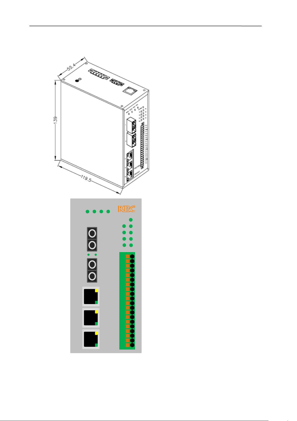
2.3 Physical Connections
PW1
TX
RX
LNK/ACT
TX
PW2
ALARM
R1
R2
R3
R4
T1
T2
T3
T4
RUN1
1
RUN2
2
RX
3
4
3
10/100M
5
LNK/ACT
ESML3-FL2-D4
Manual_hw-ESML3-FL2-D4-Rev1011
Copyright © KBC Networks Ltd. Page 6 of 18 www.kbcnetworks.com

Ethernet Switch User Manual
2.4 Installation Method
2.4.1 DIN Rail Mount
• Remove all packaging material.
• Attach the device to a DIN rail.
• Attach copper and/or fiber cables as required.
• Insert the red sleeved wire from the supplied in-line PSU into the +ve power
input and the blue sleeved wire into the –ve power input of the green male
power block terminal and tighten the screws using the flathead screwdriver
provided.
• Insert the male power block (attached to the supplied in-line PSU) to the
female power socket on the device and tighten the terminal locking screws
using the flathead screw driver provided.
See Section 2.8 for LED status.
2.4.2 Wall-mount
• Remove all packaging material.
• Unscrew the DIN rail mounting plate from the switch taking special care to
retain the 2 screws using a Phillips No.1 or No.2 screwdriver.
• Attach the supplied wall mount plate to the switch using the 2 screws that
have just been removed from the DIN rail mounting plate with a Phillips
No.1 or No.2 screwdriver.
• Position the unit on the required, flat surface and secure with screws via the
mounting plate holes. Screws are not provided.
• Attach copper and/or fiber cables as required.
• Insert the red sleeved wire from the supplied in-line PSU into the +ve power
input and the blue sleeved wire into the –ve power input of the green male
power block terminal and tighten the screws using the flathead screwdriver
provided.
• Insert the male power block (attached to the supplied in-line PSU) to the
female power socket on the device and tighten the terminal locking screws
using the flathead screw driver provided.
See Section 2.8 for LED status.
Manual_hw-ESML3-FL2-D4-Rev1011
Copyright © KBC Networks Ltd. Page 7 of 18 www.kbcnetworks.com

Ethernet Switch User Manual
2.5 Ethernet RJ45 Connections
The ESML3-FL2-D4 offers 3, 10/100 Base T/TX RJ45 ports numbered 3, 4 & 5 (see
figure 2.1). Each port is adaptive and supports auto MDI/MDI-X connection. They
can be connected by either straight through or cross-over cables to terminal devices,
servers, hubs or other switches. Each switch supports IEEE802.3x so the optimum
transmission mode (either half-duplex or full-duplex) and data rate (either 10Mbps
or 100Mbps) will be selected automatically. The connected devices should support
this feature too however, if the connected devices are not adaptive, the port will
send at the correct rate but with default mode of half-duplex.
2.6 Fiber Optic Connections
The ESML3-FL2-D4 offers two uplink redundant 100Base-FX, full-duplex fiber ports,
ports 1 & 2 (see Figure 2.1) which can be either singlemode or multimode. Each
optical connector is a duplex SC. The interface should be used in a pair (Tx and Rx),
where the Tx interface is the optical transmitting terminal which connects to the
optical receiving terminal (Rx) of the remote device. The optical Rx is the receiving
terminal which connects to the transmitting terminal (Tx) of the same optical
interface of the remote device. The two uplink redundant fiber ports can be used to
form a fiber optic redundant ring network. If a system failure occurs, the redundant
recovery time of the ring network is less than 50ms.
Figure 2.1 Switch Ports
Manual_hw-ESML3-FL2-D4-Rev1011
Copyright © KBC Networks Ltd. Page 8 of 18 www.kbcnetworks.com

Ethernet Switch User Manual
2.7 Data Ports
The ESML3-FL2-D4 offers 4 serial ports with physical connectors for RS232 or
RS485, only one of which can be supported on one port at a time. The data terminal
is wired as a 3.81mm space 20 lines phoenix terminal. The connections are as
follows:
Fig 2.2 Serial terminal wiring of ESML3-FL2-D4
2.8 Grounding / Earthing
The ESML3-FL2-D4 has an earth point located on the top panel of the switch. To
achieve the best earth connection, a circular cold-press terminal should be crimped
to one end of the earth wire and attached to the unit with the screw, making sure
that the star washer stays in contact with the body of the switch. The cross-section
of grounding wire should not be less than 2.5mm2.
2.9 LED Status
LED Status Description
Power
POWER 1
ON 24Vdc power is supplied to POWER 1 input
OFF No power is supplied to POWER 1 input
POWER 2
RUN 1
(left LED)
RUN 2*
(right LED)
ON 24Vdc power is supplied to POWER 2 input
OFF No power is supplied to POWER 2 input
System Status
ON Switch is not functioning correctly
FLASH
OFF Switch is off
ON No power is supplied to either POWER 1 or POWER 2
OFF Power being supplied to both power inputs
Switch functioning correctly
Manual_hw-ESML3-FL2-D4-Rev1011
Copyright © KBC Networks Ltd. Page 9 of 18 www.kbcnetworks.com

Ethernet Switch User Manual
100M Optical Fiber Ports LED (1 & 2)
LINK/ACT
Each RJ45 Ethernet port has two indicators, a yellow lamp and a green lamp. The yellow lamp
indicates port speed, and the green lamp indicates port link state.
10/100 (Yellow)
LINK/ACT
(Green)
ON
FLASH
OFF
Ethernet RJ45 Port Status LED (3,4 & 5)
ON
OFF
ON
FLASH Data traffic is passing through the port
OFF
ON IP address conflict
Effective network connection has been established for
the port
Data traffic is passing through the port
No effective network connection has been established for
the port
100M working status(100Base-TX)
10M working status(10Base-T)
Effective network connection has been established for
the port
No effective network connection has been established for
the port
Data Ports
ALARM
FLASH
OFF Normal operation
FLASH
T
OFF No data transmission
FLASH
R
OFF
Data port CPU operating correctly
Data being transmitted
Data being transmitted
No data transmission
*
Note: the power alarm must be active in the GUI.
2.10 Power Input Terminals
The ESML3-FL2-D4 has two green screw terminal blocks (Power Input 1 & Power
Input 2) mounted on the top panel of the switch, see Figure 2.3. The power inputs
can be used independently or they can be connected to two separate external 24V
DC power supplies to provide redundancy. The red sleeved wire should be connected
to the +ve power input and the blue sleeved wire should be connected to the –ve
power input of the green male screw block terminal.
Manual_hw-ESML3-FL2-D4-Rev1011
Copyright © KBC Networks Ltd. Page 10 of 18 www.kbcnetworks.com

Ethernet Switch User Manual
Figure 2.3 Power Input Terminals
2.11 Alarm Relay Output
The alarm terminal, which is also a green screw block terminal, (see Figure 2.3) has
two relay outputs and is used to indicate if there is a problem with the power supply
to the switch, this function must be enabled using the management software.
Figure 2.4 Alarm Terminal
2.11.1 Single Power Supply Connected:
Contacts Power On Power Off
1 & 2 Open Closed
2 & 3 Closed Open
2.11.2 Dual Power Supplies Connected:
Contacts Power On Power Off
1 & 2 Closed Open
2 & 3 Open Closed
Manual_hw-ESML3-FL2-D4-Rev1011
Copyright © KBC Networks Ltd. Page 11 of 18 www.kbcnetworks.com
Ethernet Switch User Manual
2.12 RS232 Console Interface
The console interface on the ESML3-FL2-D4 is a shielded RJ45 connector based on
3-line RS232. The switch can be connected to a 9 pin serial port of a pc using a
cable with a DM9F connector. For further information on accessing the management
software please see separate software management manual for this switch.
3 Troubleshooting
3.1 Self-testing
When the device is powered on the Power LED will be permanently illuminated
showing that there is power to the unit and the RUN1 LED and the ALARM LED will
flash.
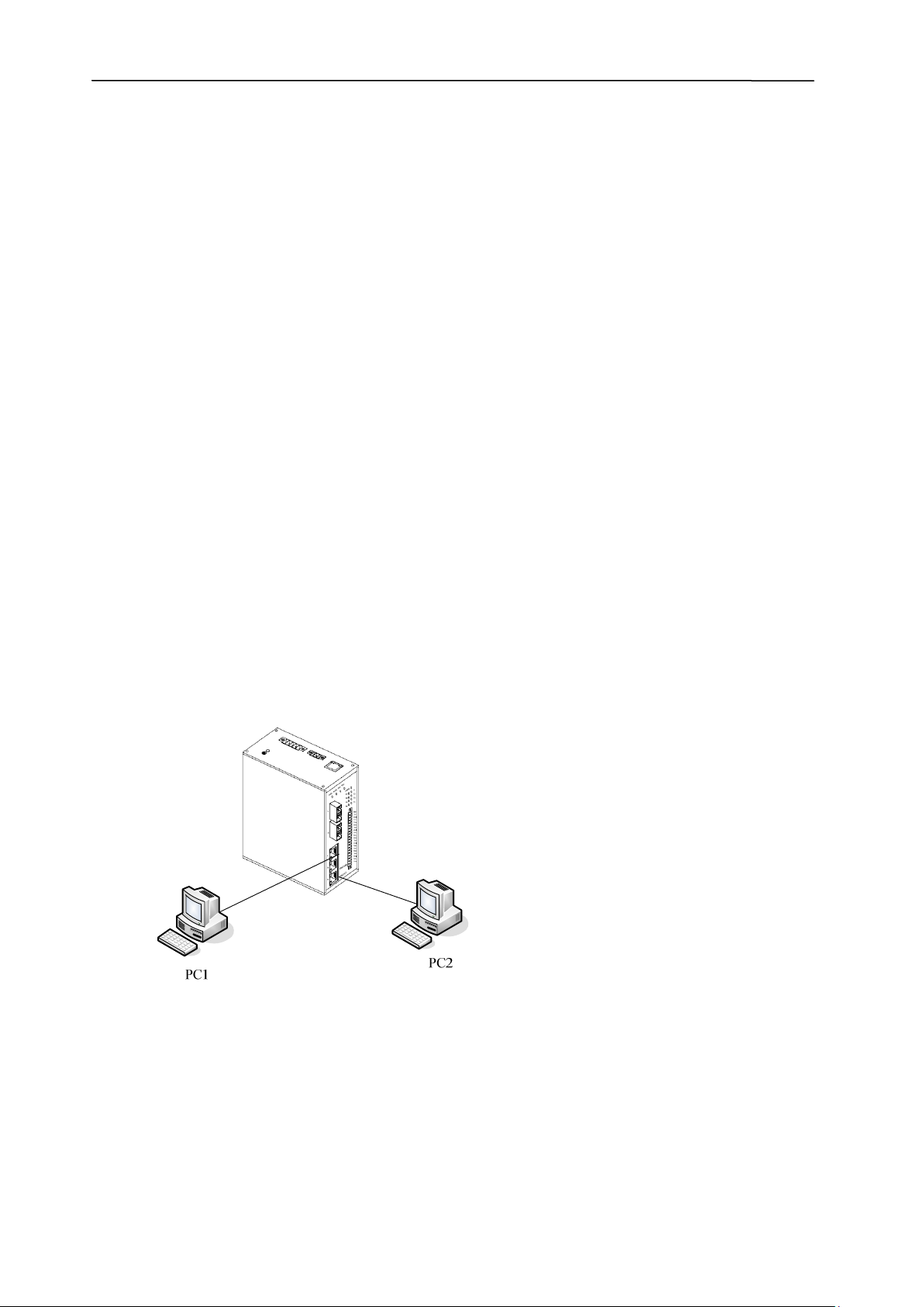
3.2 Twisted Pair Port Testing
As shown in Figure 3.1, with the switch powered on, connect two RJ45 ports from
the switch to two test computers and send the “ping” command between each
computer. If both the computers receive the complete command without packet loss
and the green LED flashes, this means that the two RJ45 ports are working correctly.
Test the other RJ45 ports as required, using the same method. During normal
operation the green LINK/ACT LED will flash to show data transfer and the yellow
10M/100M will either be off to show 10Mbps (10BASE-T) operation or on to show
100Mbps (100BASE-TX) operation.
Figure: 3.1 Testing TP Ports
Manual_hw-ESML3-FL2-D4-Rev1011
Copyright © KBC Networks Ltd. Page 12 of 18 www.kbcnetworks.com

Ethernet Switch User Manual
3.3 Fiber Port Testing
As shown in Figure 3.2, connect two ESML3-FL2-D4 units via their fiber ports. Then
attach a computer to any RJ45 port on each device and send the “ping” command
between the connected computers. If both computers get the command without
packet loss and the corresponding LINK/ACT indicators of the fiber ports flash, this
then shows the fiber ports under test are functioning correctly.
Figure 3.2 Fiber Port Testing
4 System Example
Figure 4.1 ESML3-FL2-D4 Typical System Application
Manual_hw-ESML3-FL2-D4-Rev1011
Copyright © KBC Networks Ltd. Page 13 of 18 www.kbcnetworks.com
Ethernet Switch User Manual
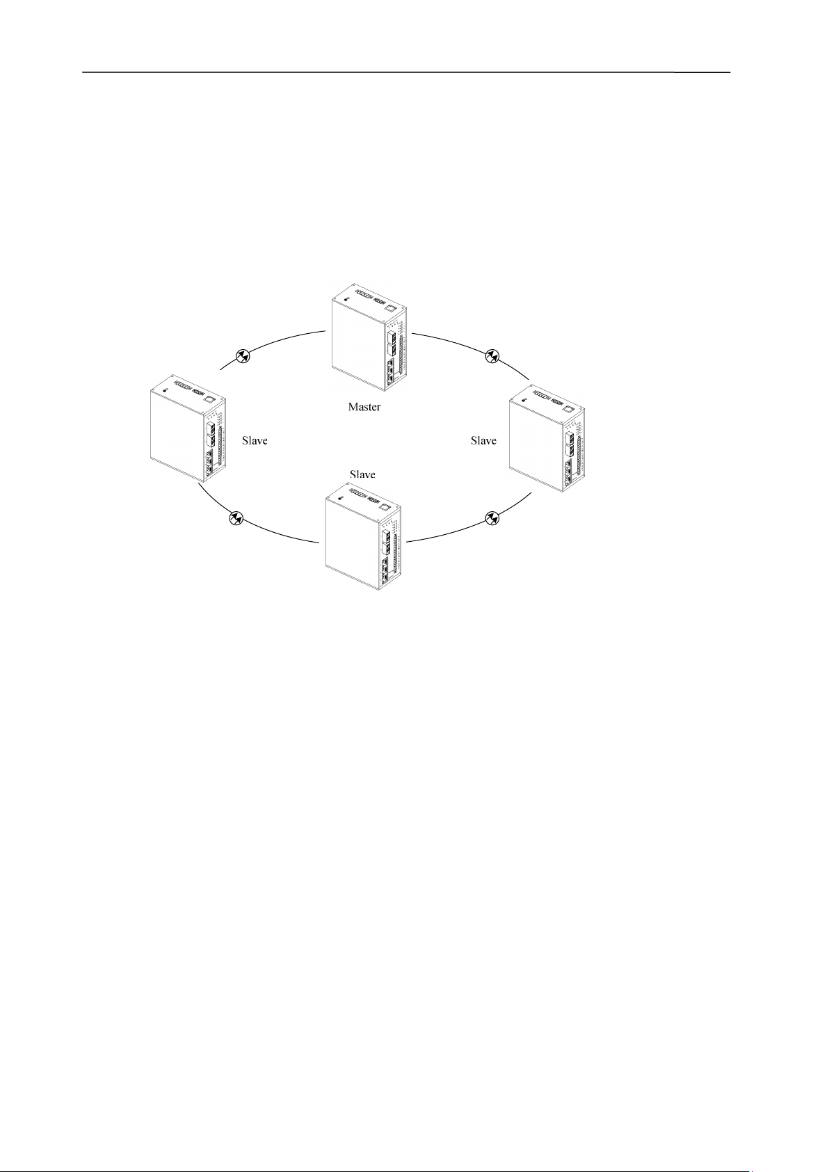
5 Networking & Configurations
The ESML3-FL2-D4 offers 3, RJ45 10/100Base-TX ports each of which can be
connected to terminal devices directly or to another industrial Ethernet switch or
hub. The ESML3-FL2-D4 also has 2 pairs of uplink 100Base-FX fiber ports which can
be used to form a redundant optical ring which has a recovery time of less than
50ms. A typical redundant ring set up is shown in Figure 5.1 below.
Figure 5.1 Typical Ring Topology
Manual_hw-ESML3-FL2-D4-Rev1011
Copyright © KBC Networks Ltd. Page 14 of 18 www.kbcnetworks.com

Ethernet Switch User Manual
6 Dimensions (mm)
Wall-mount:
Manual_hw-ESML3-FL2-D4-Rev1011
Copyright © KBC Networks Ltd. Page 15 of 18 www.kbcnetworks.com

Ethernet Switch User Manual
7 Warranty
7.1 Warranty Information
KBC extends the following LIMITED WARRANTY to the original owner/purchaser of
this product as follows:
- Two years from the date of initial sale for all wireless and network products.
- Five years from the date of initial sale for all fiber products.
1) If, within the specified warranty period, this product, or any part or portion thereof,
shall prove upon examination by KBC, to be defective in material or workmanship,
KBC will repair or replace such part or portion at KBC’s option. The warranty period
on the repaired or replaced part or portion of this product shall be limited to the
unexpired term of the original warranty. The buyer shall be responsible for all
shipping and transportation of the product to KBC for any performance under this
warranty.
2) Conditions and Exceptions:
a) Any accident to this product, any misuse or abuse, alternation, use in modified
form, or any attempt to repair this product shall void this warranty. These
conditions to the warranty include, but are not limited to, incorrect power
connections, physical damage due to mechanical shock, exposure to moisture,
and circuit modification.
b) SHOULD THIS PRODUCT PROVE DEFECTIVE FOLLOWING PURCHASE, THE BUYER,
NOT THE MANUFACTURER, DISTRIBUTOR, OR RETAILER, ASSUMES THE ENTIRE
COST OF ALL SERVICING OR REPAIR, EXCEPT AS OTHERWISE PROVIDED BY THE
TERMS OF THIS WARRANTY.
c) FOR BREACH OF ANY WRITTEN OR IMPLIED WARRANTY ON THIS PRODUCT, THE
BUYER IS LIMITED TO THE FOLLOWING DAMAGES. (1) THE COST OF LABOR TO
REPAIR OR REPLACE DEFECTIVE PARTS OR PORTIONS OF THIS PRODUCT, AND
(2) THE COST OF THE REPAIRED OR REPLACE PARTS OR PORTIONS OF THIS
PRODUCT.
d) NO OTHER EXPRESSED OR IMPLIED WARRANTIES HAVE BEEN MADE OR WILL BE
MADE ON BEHALF OF KBC WITH RESPECT TO THE SALE, REPAIR, INSTALLATION,
OPERATION, OR REPLACEMENT OF THIS PRODUCT. KBC DISCLAIMS ANY
IMPLIED WARRANTY OF MERCHANTABILITY OF THIS PRODUCT OR ITS FITNESS
FOR ANY PURPOSE, AND THE BUYER AGREES THAT THIS PRODUCT IS SOLD “AS
IS” AND THAT THE ENTIRE RISK OF QUALITY AND PERFORMANCE OF THIS
PRODUCT IS WITH THE BUYER, EXCEPT AS OTHERWISE PROVIDED BY THE
TERMS OF THIS WARRANTY.
e) Some states/jurisdictions do not allow exclusions or limitations of incidental or
consequential damages, or limitations on how long an implied warranty lasts, so
the above exclusions or limitations may not apply to you.
f) If you do not wish to be bound by any of the provisions in this warranty, please
return the product(s) immediately.
3) Contact your dealer regarding return authorizations for out of warranty repairs and
any further product information.
Manual_hw-ESML3-FL2-D4-Rev1011
Copyright © KBC Networks Ltd. Page 16 of 18 www.kbcnetworks.com

Ethernet Switch User Manual
7.2 Class A ITE
This is a Class A product. In a domestic environment this product may cause radio
interference in which case the user may be required to take adequate measures.
7.3 FCC
This equipment has been tested and found to comply with the limits for a Class A
digital device, pursuant to Part 15 of the FCC Rules. These limits are designed to
provide reasonable protection against harmful interference when the equipment is
operated in a commercial environment. This equipment generates, uses and can
radiate radio frequency energy and, if not installed and used in accordance with the
instruction manual, may cause harmful Interference to radio communications.
Operation of this equipment in a residential area is likely to cause harmful
interference in which case the user will be required to correct the interference at his
own expense.
8 Instruction of Disassembly
Instruction of Disassembly of KBC Product
(For EU Directive 2002/95/EEC-WEEE)
Tools required:
• No. 1 Phillips screwdriver
• No. 2 Phillips screwdriver
Steps for disassembly:
1. Remove tightening screws of box cover (8 screws).
2. Remove cover plate.
3. Remove tightening screws for printed circuit board (PCB).
4. Take out all PCBs.
Notice: When a product reaches the end of its life – return to KBC.
Manual_hw-ESML3-FL2-D4-Rev1011
Copyright © KBC Networks Ltd. Page 17 of 18 www.kbcnetworks.com

data delivered
Headquarters:
KBC Networks, Ltd.
25691 Atlantic Ocean Drive
Suite 3B
Lake Forest, CA 92630
U.S.A
Americas
Phone: 1-949-297-4930
Fax: 1-949-297-4933
KBC Networks Ltd. EMEA
KBC Networks Ltd.
Barham Court
Teston, Maidstone
Kent, ME18 5BZ
United Kingdom
Phone: +44(0)1622 618787
Fax: +44(0)20 7100 8147
Email: info@kbcnetworks.com
Web: www.kbcnetworks.com
 Loading...