

KBC ESMGS8-P4-B Series User Manual

ESMGS8-P4 -B WEB Management User Manual
Edition: 1.0, June 4,2017

ESMGS8-P4 Web User’s Manual
2 / 104
Table of content
1 WEB Configuration ............................................................................................................................................. 3
1.1 Preparing and Entry ............................................................................................................................. 3
1.1.1 Switch Default Configuration ...................................................................................................... 3
1.1.2 Computer basic configuration requirement .................................................................................. 3
1.1.3 Establish network connection ...................................................................................................... 3
1.1.4 Check network weather connect between computer and switch .................................................. 4
1.1.5 Login switch management interface ............................................................................................ 4
1.2 Web management interface .................................................................................................................. 5
1.2.1 Basic information ......................................................................................................................... 5
1.2.2 Configuration ............................................................................................................................... 7
5.2.3 Monitor(Status Display)............................................................................................................... 67
5.2.4 Diagnostics................................................................................................................................... 93
5.2.5 Maintenance ................................................................................................................................. 95
2 Command Line Management ............................................................................................................................. 99
2.1 Configure HyperTerminal .................................................................................................................. 99
2.1.1 USB(115200-8-N-1)port connect with Device console port ................................................ 99
2.2 Login equipment and basic command Query .................................................................................. 100
2.2.1 System Information Query ....................................................................................................... 100
2.2.2 Recovery factory default .......................................................................................................... 101
2.2.3 Logout ...................................................................................................................................... 101
2.2.4 Query / ModifyIP ..................................................................................................................... 101
2.2.5 Using own command help function ......................................................................................... 102
3 Technical Parameters ....................................................................................................................................... 103
1 WEB Configuration
1.1 Preparing and Entry
Configure the switch through Web pages, this chapter will take you through the equipment configuration process.
After completing the hardware installation, you need to ensure that the computer networks parameters to meet certain
conditions before accessing the Settings page.
1.1.1 Switch Default Configuration
The system default IP address is: 192.168.0.240, user name: admin; password: admin
1.1.2 Computer basic configuration requirement
Ethernet card installed, you can access the Internet through a network port. we recommend using a Computer (or
better), minimum display resolution support 1024 * 768 pixels for better view.
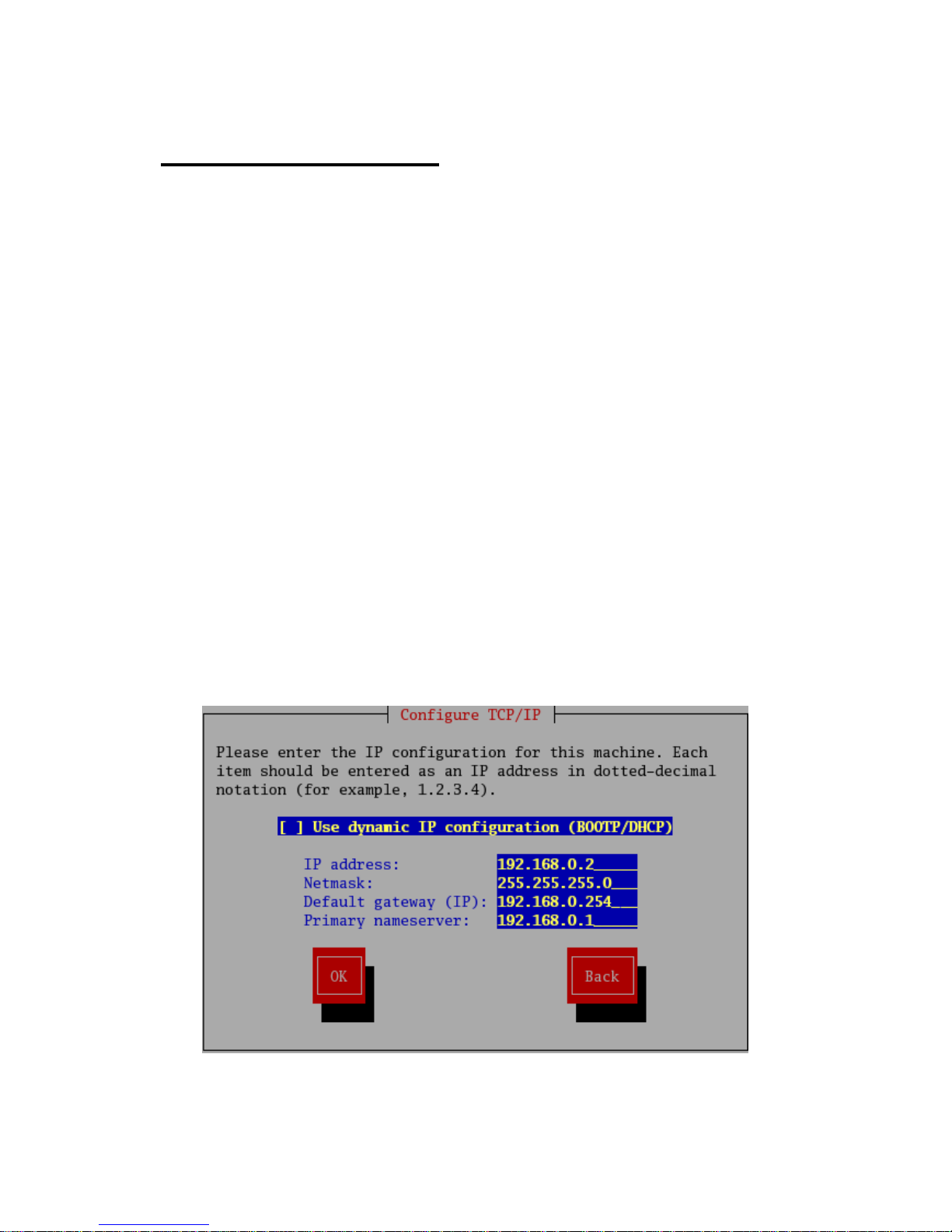
1.1.3 Establish network connection
Open network parameter configuration of Computer shown as below。
Select the Internet Protocol (TCP / IP), enter the Internet Protocol (TCP / IP) Properties window. Select the input IP
address in addition to the default IP address and subnet mask (255.255.255.0), click on the OK button to complete
ESMGS8-P4 Web User’s Manual
4 / 104
the operation.
(Note: The IP address and switch must be in the same subnet.)
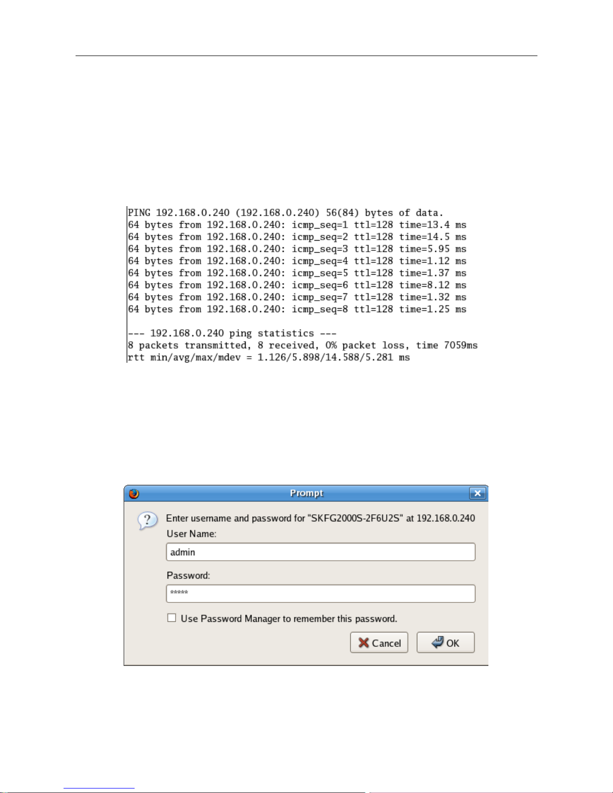
1.1.4 Check network whether connect between computer and switch
Use the ping command of Operating System, enter switch’s IP address, if reply normally, then network
connectivity; otherwise, check the network connection.
1.1.5 Login switch management interface
Running the browser, enter the switch default IP address (192.168.0.240) in address column, click Enter. Login dialog
box, as shown below, enter your user name and password (the default user name: admin, password: admin), click the
OK button or directly enter into the system configuration page. After a successful login interface as follows:
ESMGS8-P4 Web User’s Manual
5 / 104
1.2 Web management interface
1.2.1 Basic information
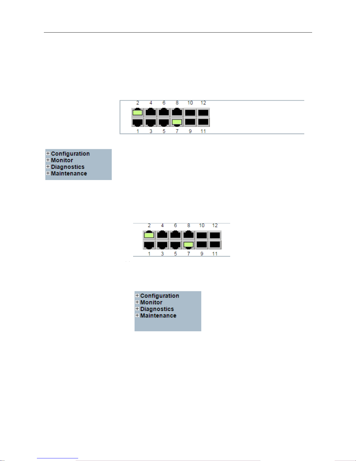
Switch Configuration page is divided into Configuration, Manager, Diagnostics, Maintenance of four parts. As below:
Port State Overview:This area displays the current status of the device connection port. When the indicator is
green indicates that the corresponding port is connected, the indicator is gray, indicating the port not connected or
enabled, as shown below:
Navigation column: Click on a navigation column entry, the user can make the appropriate feature set and view, as
shown below:
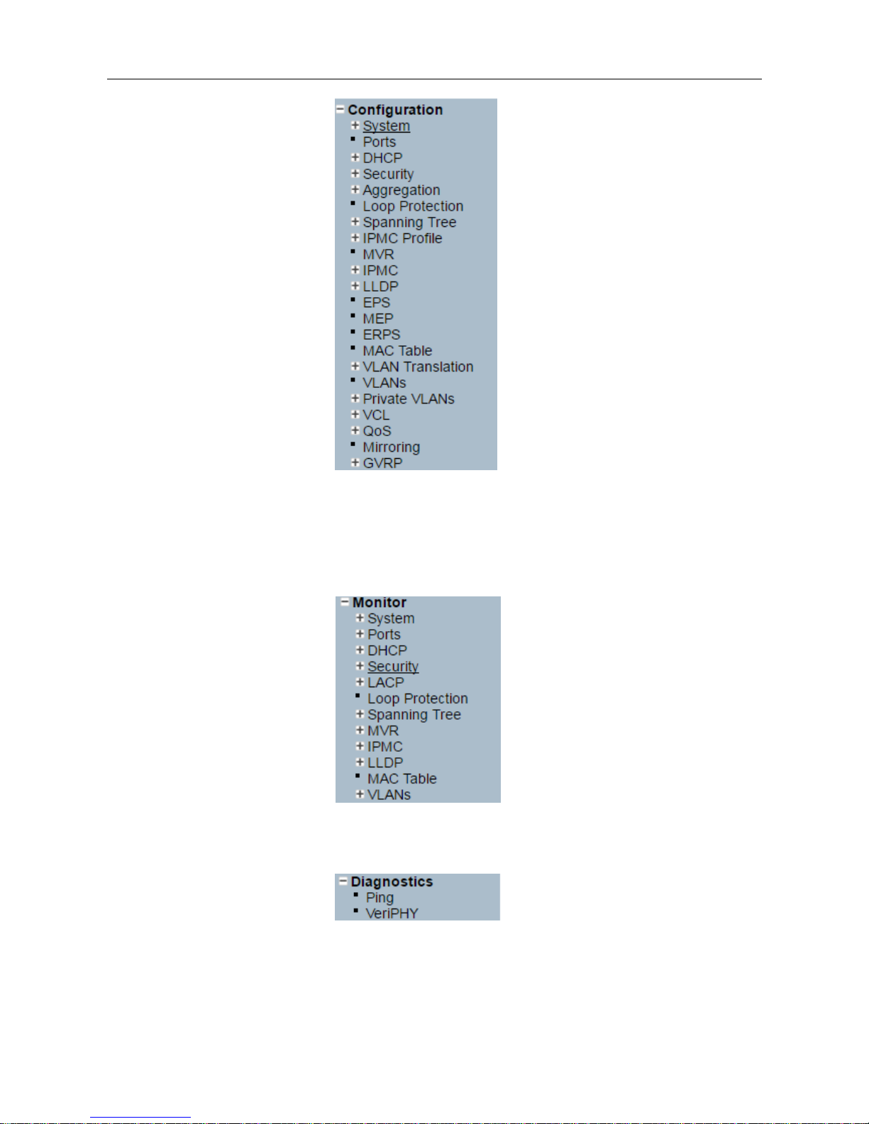
Configuration:Click the navigation column Configuration option, the system will expand to show the relevant
configuration interface, users can set the interface-related functions.
ESMGS8-P4 Web User’s Manual
6 / 104
Monitor:Click on the navigation column Monitor option, the system will expand to show the relevant status
interface, user-related functions can be provided in the interface.
Diagnostics:Click on the navigation column Diagnostics option, the system will expand the relevant components
for switch device detection.
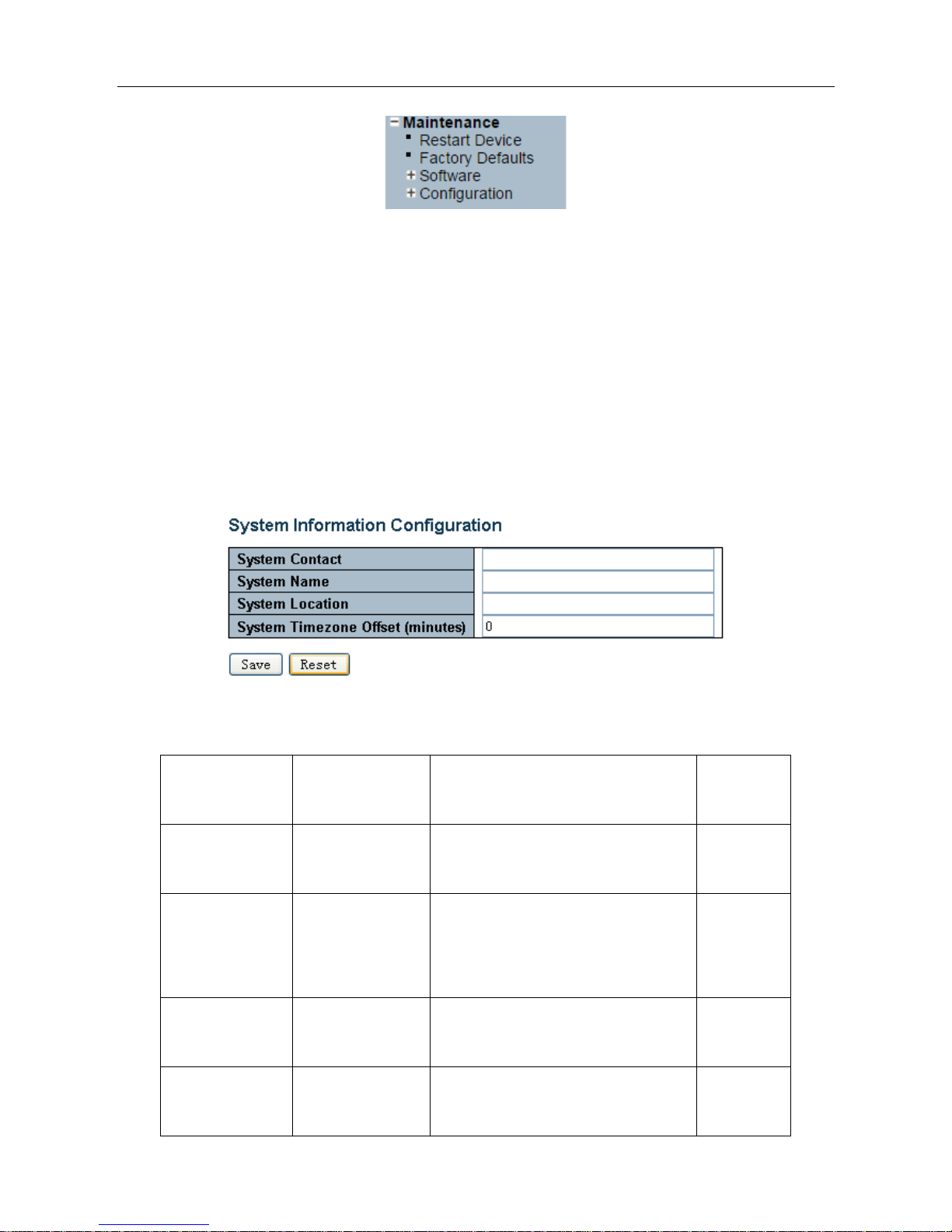
Maintenance:Click on the navigation column Maintenance option, the system will be displayed in the
management area related to user management interface related functions can be provided in the interface.
ESMGS8-P4 Web User’s Manual
7 / 104
1.2.2 Configuration
1.2.2.1 System
A. System information
Enter 【System】→【Information】navigation column, enter the system contact, system name, system location,
time zone offset system after setting, click [Save] button to complete the basic configuration information.
Click 【Reset】button, return to the data before system 【Save】
Interface items introduction:
Interface items
Configuration
Introduction
Factory
configuration
System Contact
0~255 characters
Equipment maintenance personal contact
information
No
System Name
0~255 characters
Switch name, is used to specify switch
function (The first must be a letter, the
last one cannot be a special sign)
No
System Location
0~255 characters
Describing the location information of
device, such as production line 1
System Time zone
Offset
-720~720,unit:min
offset between equipment time zone and
system time zone
0
ESMGS8-P4 Web User’s Manual
8 / 104
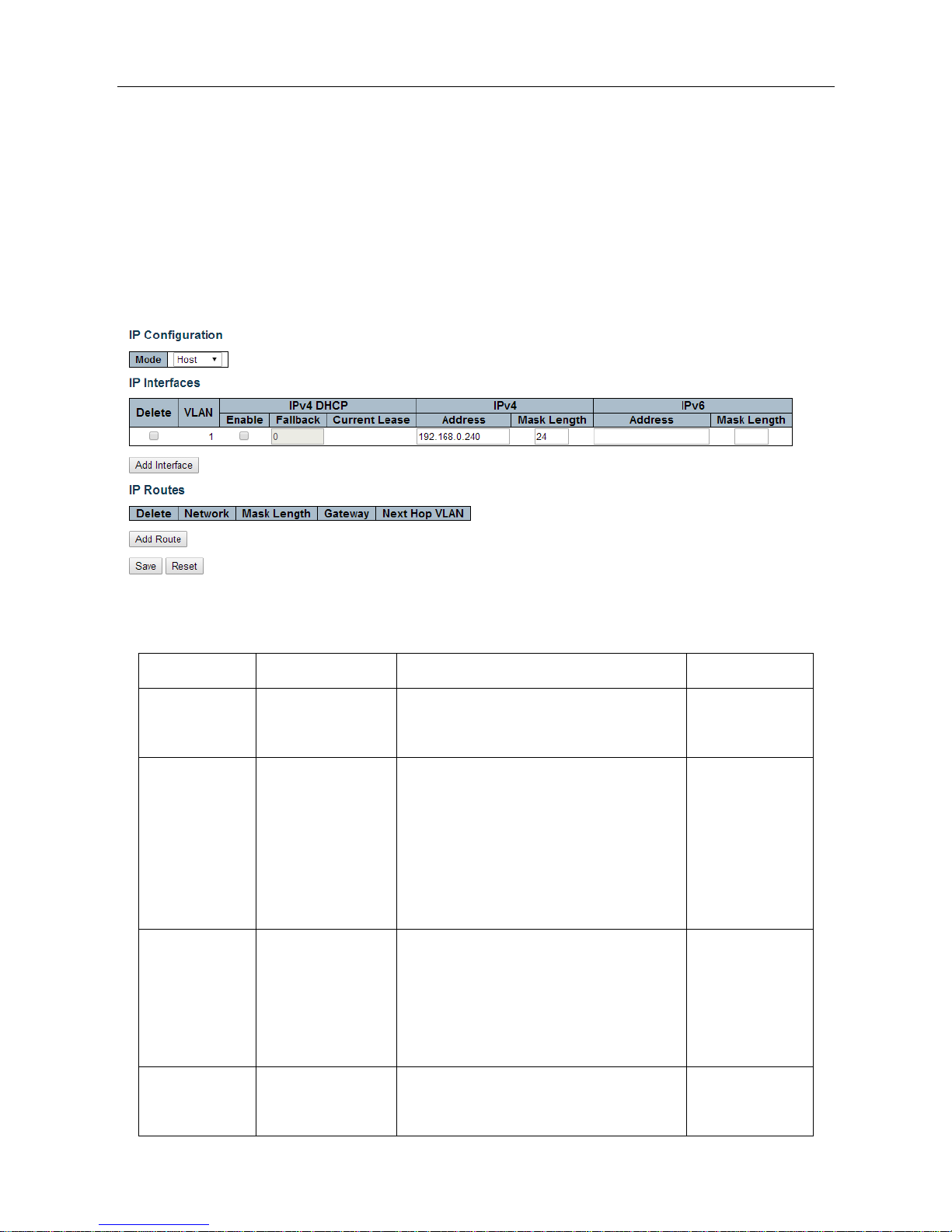
B. IP address configuration
Enter [System] → [IP] navigation column, the page used to configure the address of the device management. The
current status address of the device, a mask, router will be displayed in the form. After modifying the contents of the
form, click [Save] button to complete the address modification or click [Reset], it will be restored to the original
value form content unmodified.
Router is optional item, default is empty. Set relevant parameters, click [Save] button to complete the configuration.
IP interface:interface items introduction(May different VLAN set different IP addresses, to meet the different
hosts in VLAN access to the switch)
Interface items
configuration
introduction
Factory setting
Delete
Select / not selected
Select this option to delete an existing IP
interface.
not selected
VLAN
1~4095 number
The VLAN associated with the IP interface.
Only ports in this VLAN will be able to
access the IP interface. This field is only
available for input when creating an new
interface.
No
DHCP
Select / not selected
Enable the DHCP client by checking this
box. If this option isenabled, the system will
configure the IP address and mask of the
interface using the DHCP protocol.
not selected
Address
Switch IP address
The IPv4 address of the interface in dotted
decimal notation.
192.168.0.240
ESMGS8-P4 Web User’s Manual
9 / 104
Mask Length
1-30
The destination IP network or host mask, in
number of bits (prefix length).
24
Add Interface
Add an IP address settings
Click “Add Interface “Add a new IP interface。
IP router:Interface items introduction:
Interface items
configuration
introduction
Factory setting
Delete
Select / not selected
Select this option to delete an existing IP
route.
not selected
Network
IP address
The destination IP network or host
address of this route. Valid format is
dotted decimal notation or a valid IPv6
notation. A default route can use the value
0.0.0.0 or IPv6 :: notation.
NO
Mask Length
1-32
The destination IP network or host mask,
in number of bits (prefix length). It
defines how much of a network address
that must match, in order to qualify for
this route.
24
Gateway
IP
The IP address of the IP gateway.
No
Add Route
Add a IP route configuration
Click “Add Router” to add a new IP route interface.
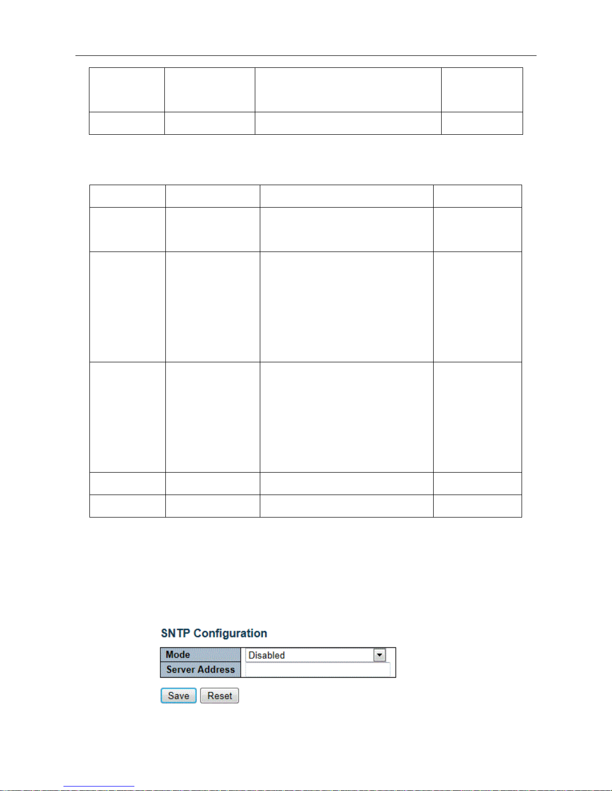
C. SNTP time server configuration
Enter【System】→【SNTP】Navigation, Time server configuration page, can be turned on when the remote NTP
server, and configure remote SNTP time server, click [Save] button to complete time server configuration。
ESMGS8-P4 Web User’s Manual
10 / 104
Interface items introduction:
Interface items
configuration
introduction
Factory setting
Mode
Disable/Enable
Indicates the NTP mode operation.
Disable
Server Address
Time server IP address
Provide the IPv4 or IPv6 address of
a NTP server.
No
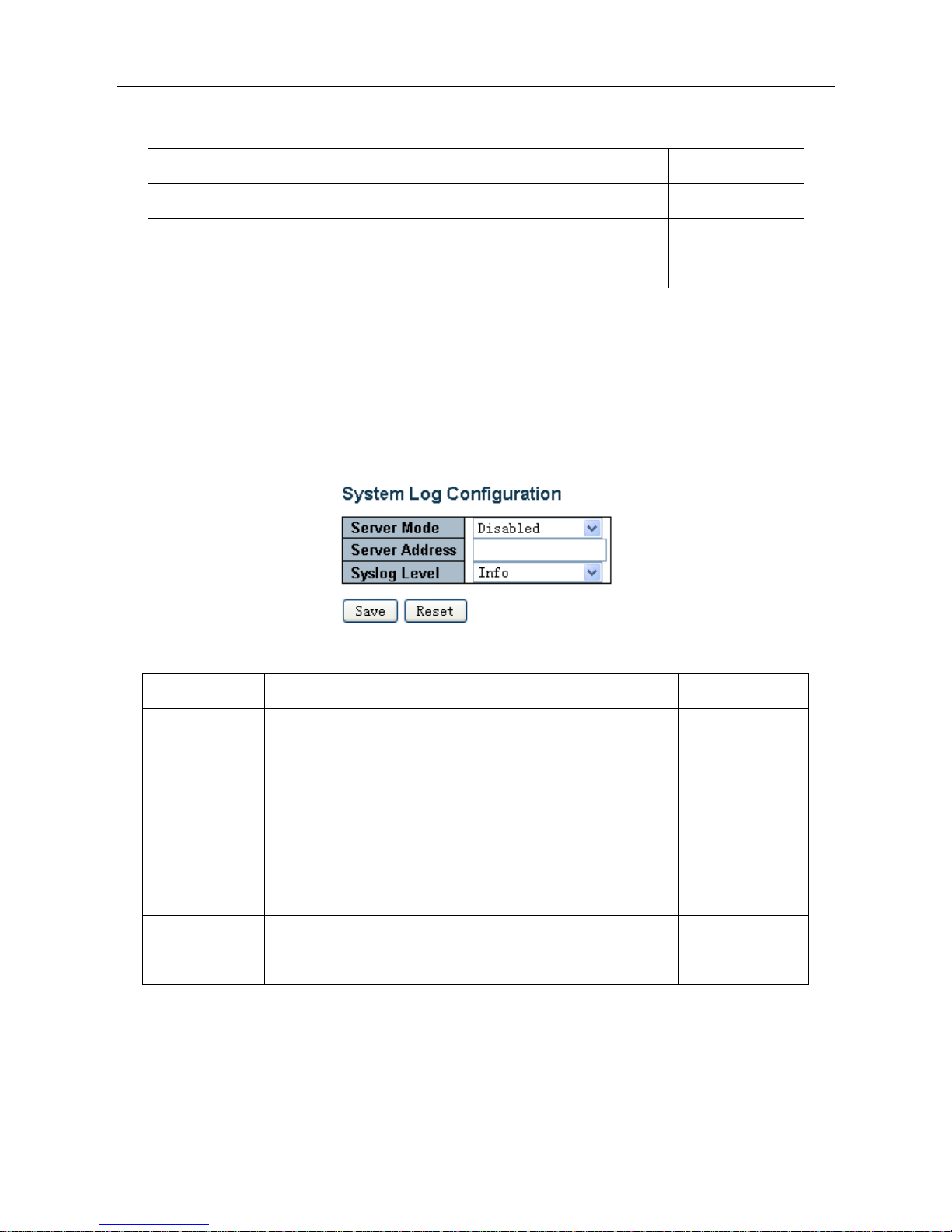
D. Log Server Configuration
Enter [System] → [Log] navigation column, log configuration page, you can configure a remote logging server
information, the device logs information [Save] to a remote server, providing backup viewing. Select the server mode,
set the server address, select the log level, click [Save] button to complete the system logging configuration.
Interface items introduction:
Interface items
Configuration
Introduction
Factory setting
Server Mode
Disable/Enable
Indicates the server mode operation.
When the mode operation is enabled,
the syslog message will send out to
syslog server.
Disable
Server Address
Log configuration IP
address
Configure log server IP address
No
Syslog Level
Info/Warning/Error
Indicates what kind of message will
send to syslog server.
Info
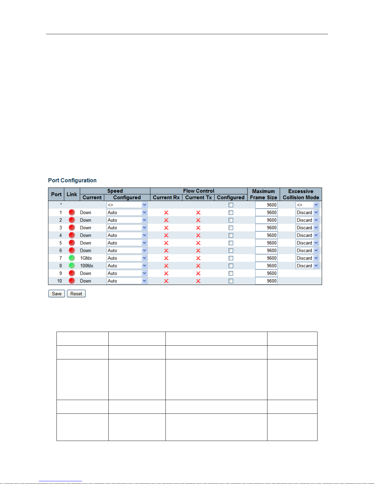
5.2.2.2 Ports
Enter the [Ports] navigation column, you can view the connection status of each port, including: link connection,
speed, flow control and maximum frame size and other information, No 1-6 for the front panel port 100M / 1000M
ESMGS8-P4 Web User’s Manual
11 / 104
RJ45 ports, No 7-8 port for the data connection port, No 9-10 port Gigabit optical interfaces. Link status indication
red indicates that the link down state; green indicates that the link up state.
Port rate mode:
Ports can be selected as "Auto", "Disabled", "10mbps HDX", "10mbps FDX", "100Mpbs HDX", "100Mpbs FDX",
"1Gbps FDX";
This option may be set directly: Auto can automatic identification access type.
Flow Control: enable the port flow control, implement port flow control
The maximum frame size that can be configured port maximum transmission unit, the default is 9600. Select the
relevant parameters, click [Save] button to complete the port configuration. Also Click [Save] button to save changes.
Click [Reset]to cancel any changes made locally and return to previously saved values.
Interface items introduction:
Interface items
Configuration
Introduction
Factory setting
Port
Physical port number
Link
Port status display, a red light indicates
that the link is disconnected status,
green indicates normal connection link
Speed Current
Info/Warning/Error
Display port status and mode
Info
Speed
Configured
Disable
Prohibition to transfer data through the
port
Disable
ESMGS8-P4 Web User’s Manual
12 / 104
Auto
Allows the port and the connected
devices automatically adjust speed
according to IEEE 802.3u
10Mbps HDX
In accordance with the rate selection,
full / half duplex communication rate
and to determine its mode of operation.
10Mbps FDX
100Mbps HDX
100Mbps FDX
1Gbps FDX
Flow Control
Current Rx
Indicates whether received the port flow
control pause frames
X
Flow Control
Current Rx
Indicate port whether send the flow
control pause frames
X
Flow Control
Configured
Check / uncheck
On / off flow control
uncheck
Maximum Frame
Size
64-10056Byte
Set the port of the maximum data frame
length
9600
Excessive
Collision Mode
Discard/Restart
When the transfer conflict, whether
retransmission of dropped packets:
discard / retransmission
Discard
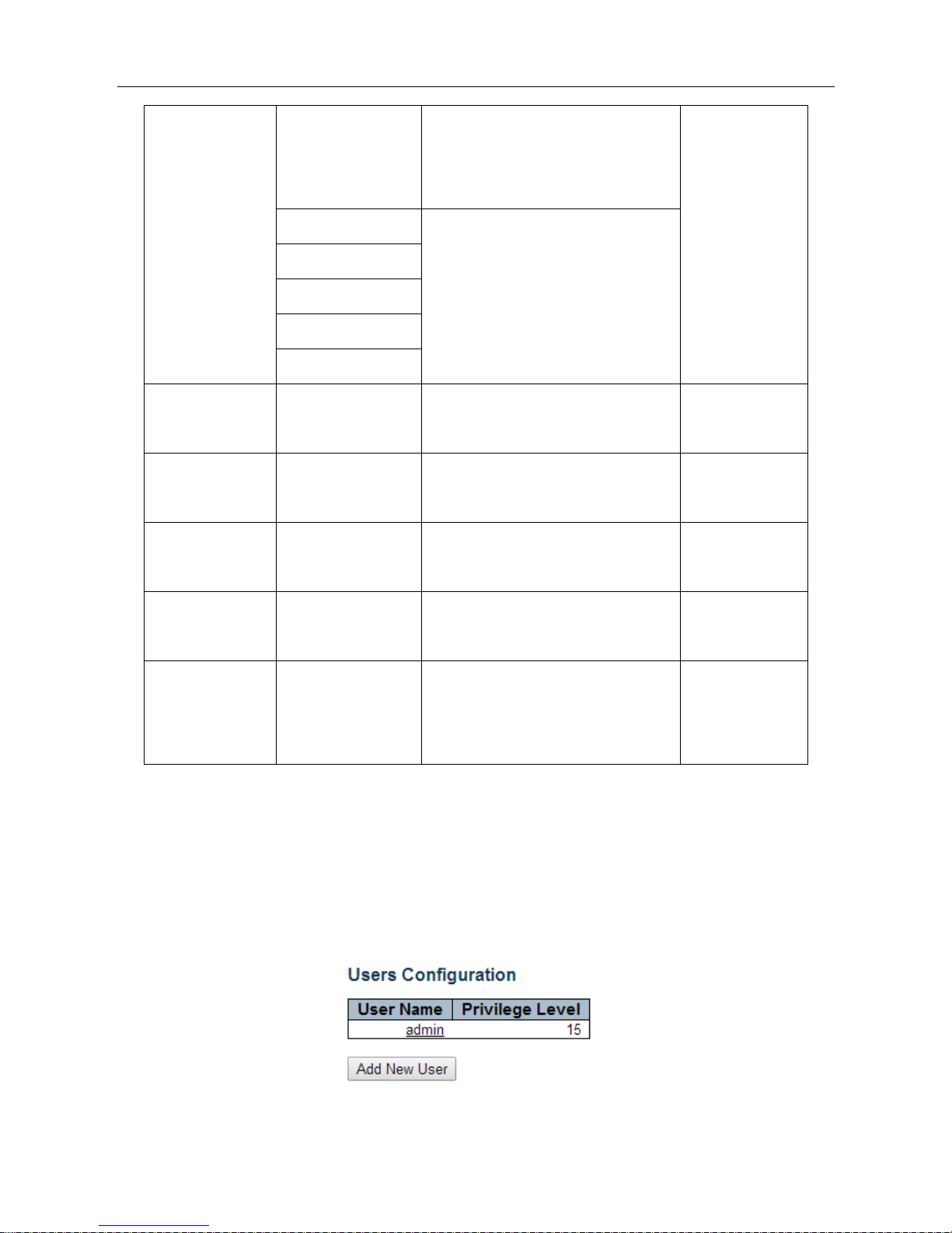
5.2.2.3 Security
A. System password configuration
Enter [Switch] → [User] navigation column, this page is used to add users, change user account password; important
to remember the new password, the password is lost login prevent equipment failure.
ESMGS8-P4 Web User’s Manual
13 / 104
Interface items introduction:
Interface items
Introduction
Add New User
Add new user
User Name
User name
Password
password
Password(again)
Confirm password
Privilege Level
Level(The higher the value, the greater the level)
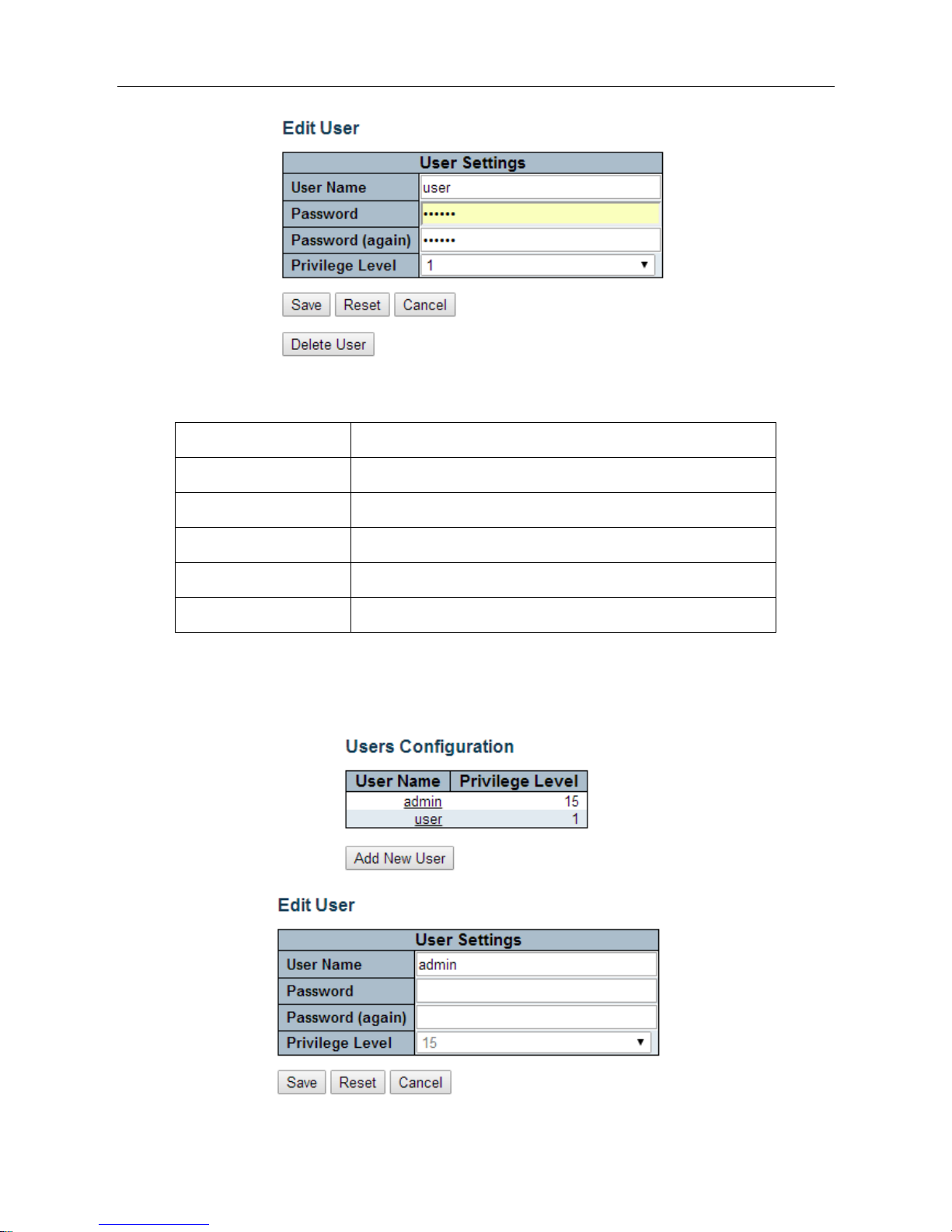
Modify the account password
In the User Interface, click the account that you want to modify;
Interface items introduction:
ESMGS8-P4 Web User’s Manual
14 / 104
Interface items
Introduction
Old Password
Enter the password currently used, if the old password is entered
incorrectly, the new password is not enabled
New Password
Enter the new password, the length of the bit characters <0-30>
characters
Confirm New Password
Re-enter the same new password, or can not be enabled
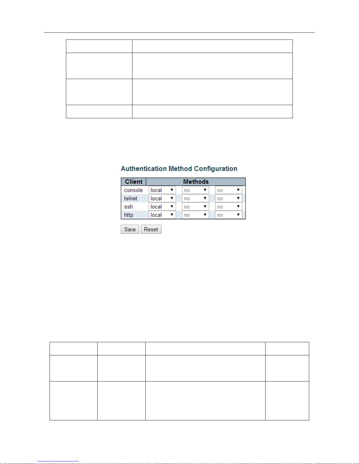
B. Login authentication mode setting
Enter [Switch] → [Auth Method] navigation column, this page is used to set the manner in which authentication
when users access the switch .
When you select the authentication mode is "none", no authentication enabled, you cannot login into the system.
When you select the authentication mode is "local", enable user name and password to log in the system's local user
database.
When you select the authentication mode is "radius", enable remote server for authentication.
Set relevant parameters, click [Save]to save changes.
Click [Reset] to undo any changes made locally and revert to previously saved values.
Interface items introduction:
Interface items
configuration
introduction
Factory setting
Client
Console/http
As client user in console / web / telnet / ssh mode
access system
Methods
none/local/radius
After users access the system the authentication
modes: non-authentication / local authentication /
remote server authentication, you can select local
local
ESMGS8-P4 Web User’s Manual
15 / 104
authentication and remote authentication server
certificate as the same time
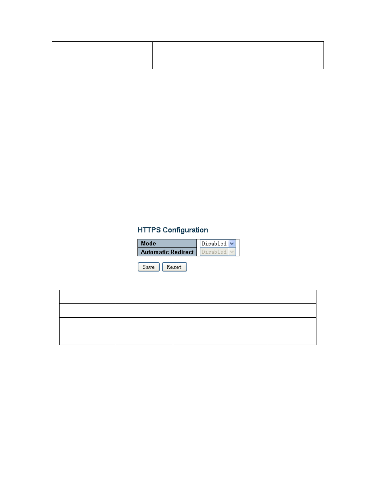
C. HTTPS Configuration
Enter 【Switch】→【HTTPS configuration】navigation column, This page is used to enable the system's web
connection is HTTP / HTTPS (secure HTTP). When users enable the HTTPS Meanwhile enable HTTPS automatic
redirection function, the system will automatically select web mode into the system.
When the user closes the HTTPS mode, the system will select HTTP mode into the system. It must enable HTTPS
mode to enable "automatic redirection" feature.
Select the relevant parameters, click [Save] to complete the HTTPS configuration; click [Reset] settings to the default
values.
Interface items
configuration
introduction
Factory setting
Mode
Disable/Enable
Off / On HTTPS access switch
Disable
Automatic
Redirect
Disable/Enable
Off / On automatic redirection
between HTTP / HTTPS
Disable
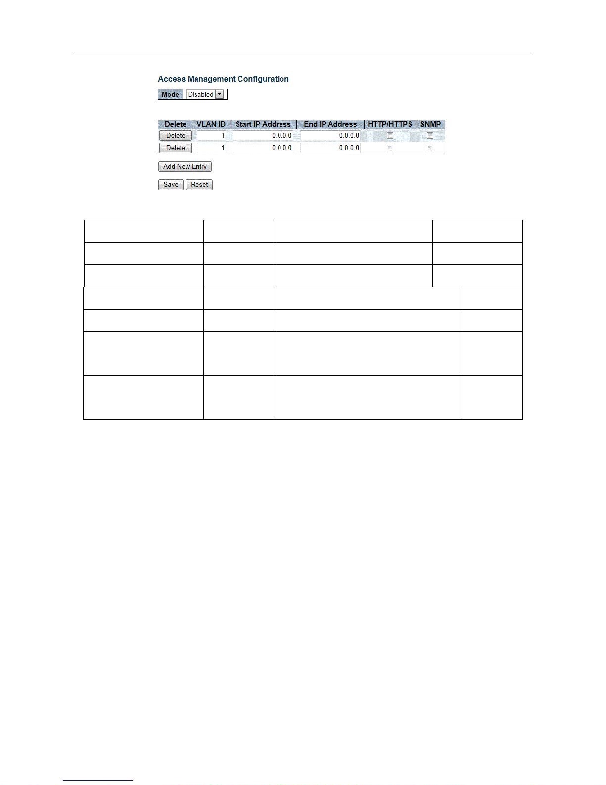
D. Access management configuration
Enter 【Switch】→【Access Management】navigation column,Page is used to regulate the access management.
Select Open access control management mode, click on the "Add New Entry" button, typing "Start IP Address
(beginning IP address)", "End IP Address (End IP address)", select "HTTP / HTTPS", "SNMP", at least select a
permissible service.
Click [Save] button to complete the access management configuration. Check delete selection on the corresponding
clause, click the check box to complete the deletion.
ESMGS8-P4 Web User’s Manual
16 / 104
Interface items introduction:
Interface items
Configuration
Introduction
Factory setting
Mode
Disable/Enable
off/one access control management
Disable
VLAN ID
1-4095
IP segment belongs VLAN
1
Start IP Address
IP Address
Access the start IP address
0.0.0.0
End IP Address
IP address
Access the end IP address
0.0.0.0
HTTP/HTTPS
Select / not
selected
Selected, The IP address can accessed
through HTTP/HTTPS
Not selected
SNMP
Select / not
selected
Selected, The IP address can accessed
through SNMP
Not selected
Add New Entry: Click to add a new interface.
Delete:
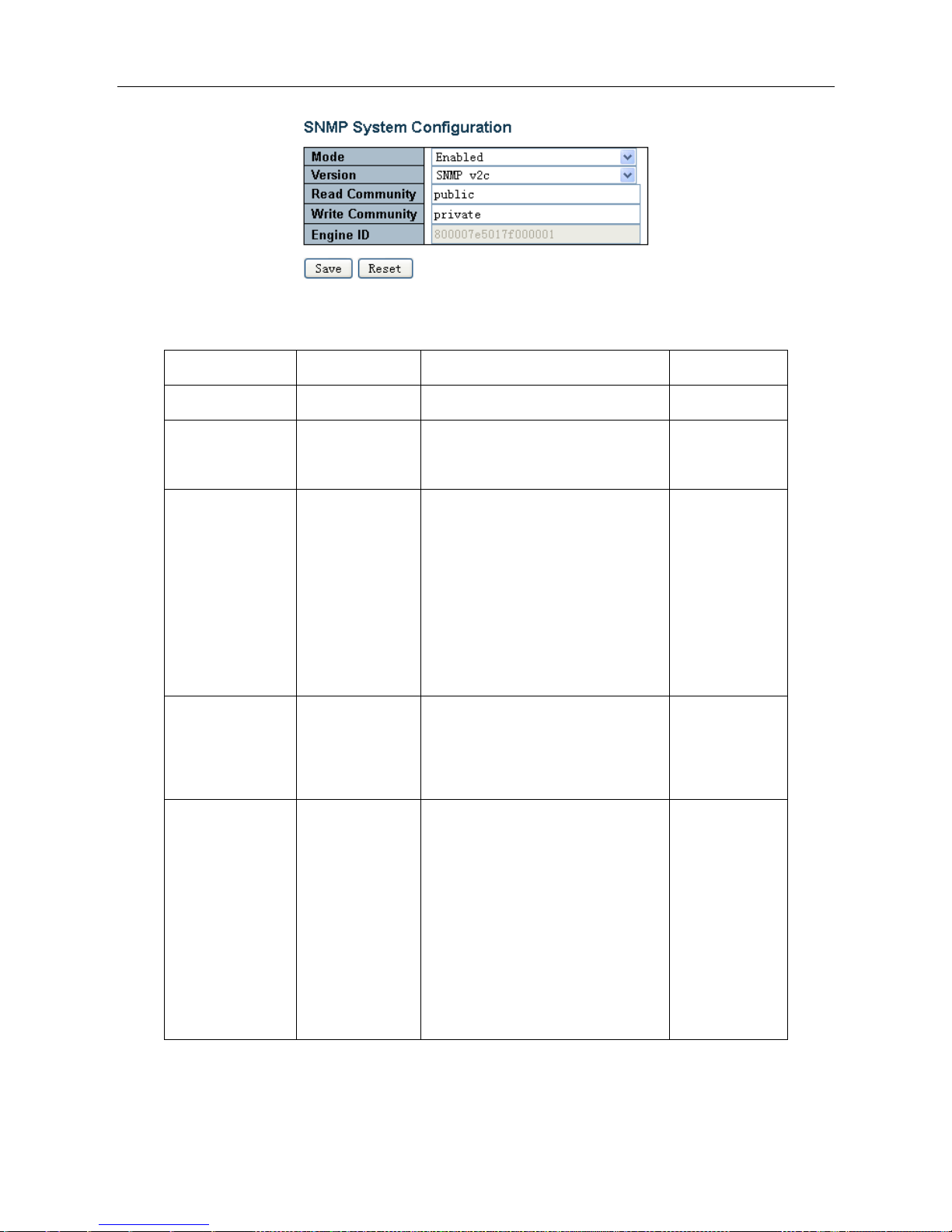
5.2.2.4 SNMP Configuration
A. SNMP system configuration
Enter 【SNMP configuration】→【System】navigation column,If your network is configured with the SNMP server,
the switch can configure SNMP parameters, connect the SNMP server. When selected SNMP v3 version needs to be
configured for specific functional parameters about SNMP v3 security certification, groups, views and so on.
ESMGS8-P4 Web User’s Manual
17 / 104
Interface items introduction:
Interface items
configuration
introduction
Factory setting
Mode
Disable/Enable
Indicates the SNMP mode operation.
Enable
Version
SNMP V1/SNMP
V2C/SNMP V3
Indicates the SNMP supported
version.
SNMP V2C
Read Community
0-255 string
Indicates the community read access
string to permit access to SNMP
agent.
The allowed string length is 0 to 255,
and the allowed content is the ASCII
characters from 33 to 126.
Public
Write
Community
0-255 string
Indicates the community write access
string to permit access to SNMP
agent.
private
Engine ID
16Decimal
Indicates the SNMPv3 engine ID. The
string must contain an even number(in
hexadecimal format) with number of
digits between 10 and 64, but all-zeros
and all-'F's are not allowed. Change of
the Engine ID will clear all original
local users.
800007e5017f000
001
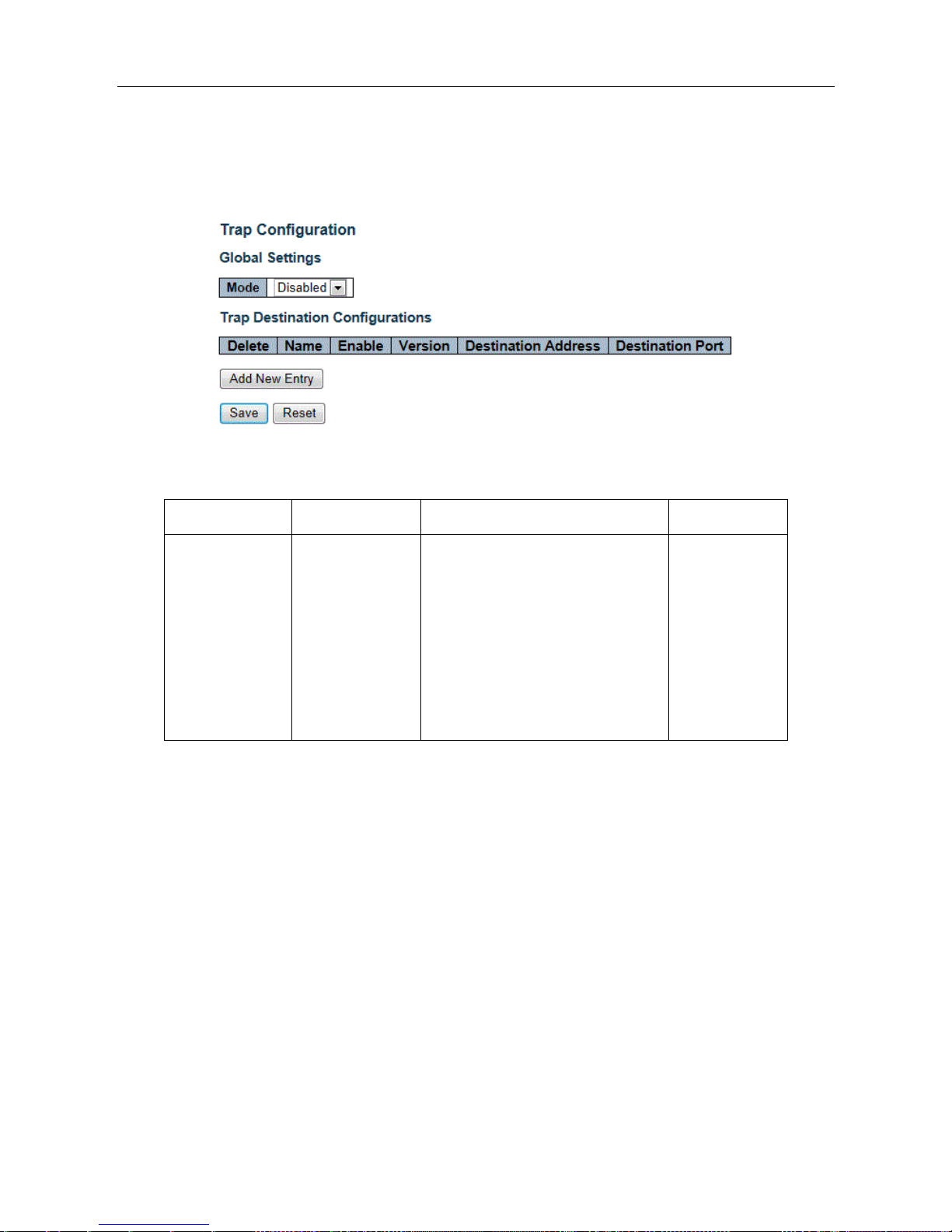
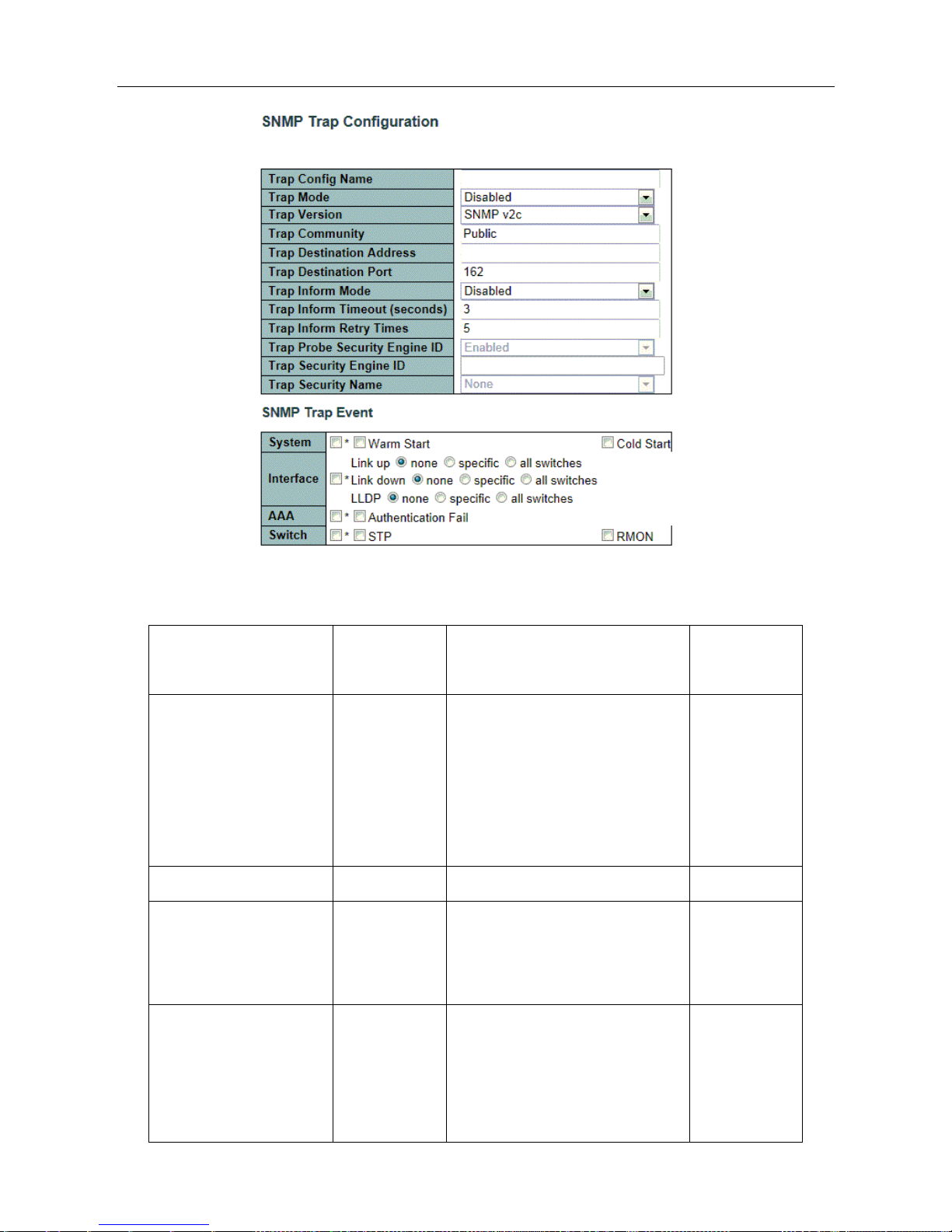
B. SNMP Trap Configuration
Enter 【SNMP configuration】→【Trap】,This page is used to configure the SNMP Trap function. The feature
set SNMP Trap Active upload function followed protocol version, community, destination IP address, port number,
ESMGS8-P4 Web User’s Manual
18 / 104
and whether to use the Trap Inform, if you use Trap Inform, the corresponding timeout, retransmission parameters,
and safety Engine ID. While providing local support for those events triggered Trap, such as: switch hot start, cold
start, port status, authentication fails.
Interface items introduction:
Interface items
Configuration
Introduction
Factory setting
Mode
Disable/Enable
Indicates the trap mode operation.
Possible modes are:
Enabled: Enable SNMP trap mode
operation.
Disabled: Disable SNMP trap mode
operation.
Disable
Add New Entry: add button, Click to expand Trap configuration view
ESMGS8-P4 Web User’s Manual
19 / 104
Interface items introduction:
Interface items
Configuration
Introduction
Factory
setting
Trap Config name
0~255 Byte
Indicates which trap Configuration's
name for configuring. The allowed
string length is 1 to 255, and the
allowed content is ASCII characters
from 33 to 126.
No
Trap Mode
Disable/Enable
Indicates the SNMP mode operation.
Disable
Trap Version
SNMP
V1/SNMP
V2C/SNMP V3
Indicates the SNMP supported
version.
SNMP V2C
Trap Community
Public/private
String
Indicates the community access
string when sending SNMP trap
packet. The allowed string length is 0
to 255, and the allowed content is
Public

ESMGS8-P4 Web User’s Manual
20 / 104
ASCII characters from 33 to 126.
Trap Destination Address
IP address
Indicates the SNMP trap destination
address. It allow a valid IP address in
dotted decimal notation ('x.y.z.w').
No
Trap Destination Port
Port address
Indicates the SNMP trap destination
port. SNMP Agent will send SNMP
message via this port, the port range
is 1~65535.
162
Trap Inform Mode
Disable/Enable
Indicates the SNMP trap inform
mode operation.
Disable
Trap Inform Timeout
0-2147 second
Indicates the SNMP trap inform
timeout.
The allowed range is 0 to 2147.
3
Trap Inform Retry Times
0-255 time
Indicates the SNMP trap inform retry
times.
The allowed range is 0 to 255.
5
Trap Probe Security
Engine ID
Disable/Enable
Indicates the SNMP trap probe
security engine ID mode of
operation.
Trap Security Engine ID
10-64
hexadecimal
digits, not
allowed all 0,
all 1
Indicates the SNMP trap security
engine ID.
ProbeFail
Trap Security Name
Indicates the SNMP trap security
name.
SNMPv3 traps and informs using
USM for authentication and privacy.
A unique security
name is needed when traps and
None
ESMGS8-P4 Web User’s Manual
21 / 104
informs are enabled.
Trap Event
Configure SNMP trap on this page.
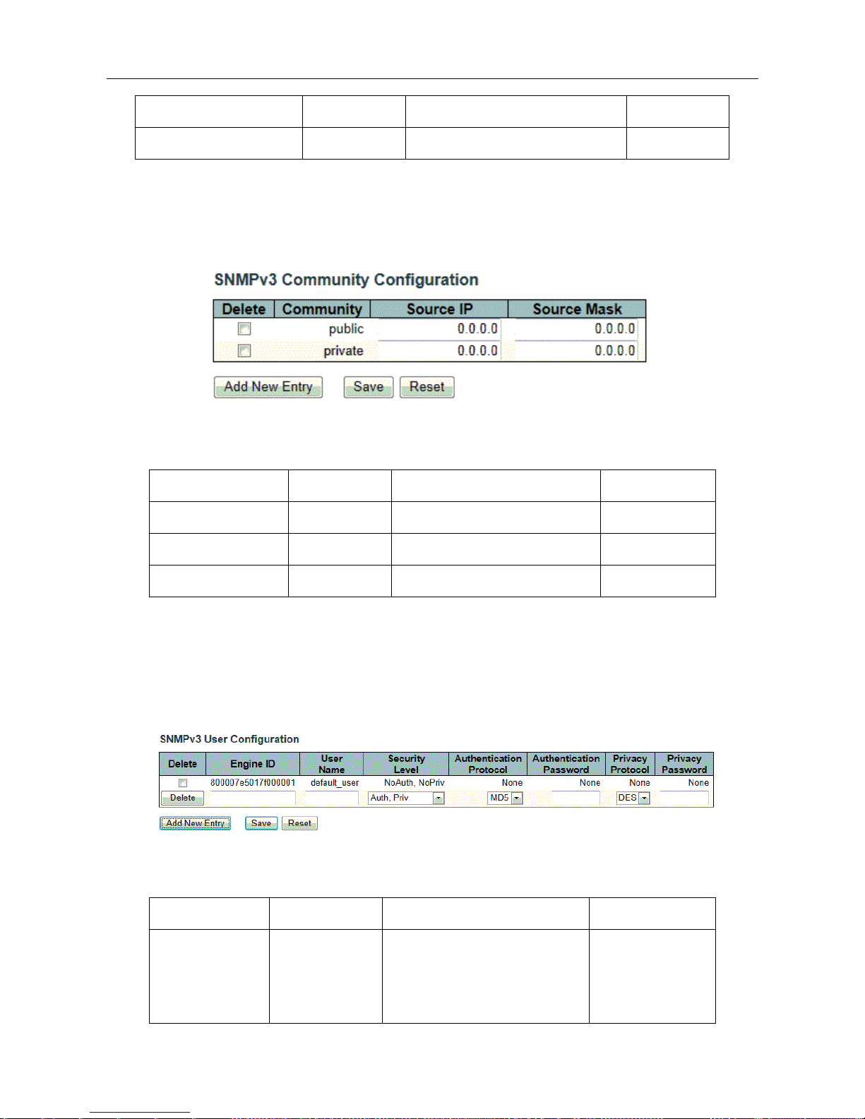
C. SNMP Community Configuration
Enter【SNMP Configuration】→【Community】navigation column,Configure SNMPv3 community table
on this page. This function is used for only one IP address to restrict the information requested or received.
Interface items introduction:
Interface items
Configuration
Introduction
Factory setting
Community
0~255 byte
Community (Authenticate string)
No
Source IP
IP address
Community Source IP address
0.0.0.0
Source Mask
Subnet Mask
Community Source Mask
0.0.0.0
D. SNMP Users Configuration
Enter【SNMP Configuration】→【Users】navigation column, Configure SNMPv3 user table on this page.
Configure Authentication security mode, security level, and data reported level of security, encryption mode
for particular user when access identity verification when accessing
Interface items Introduction:
Interface items
Configuration
Introduction
Factory setting
Engine ID
16Decimal
Engine IDAs Engine ID
authoritative SNMP it used to
identify SNMP entities,
800007e5017f0000
01
ESMGS8-P4 Web User’s Manual
22 / 104
authentication and encryption
User Name
0-32 byte
User name
0.0.0.0
Security Level
NoAuth,NoPriv
Security levels: no authentication,
no privacy
NoAuth,NoPriv
Auth,NoPriv
authentication, no Privacy
Auth,Priv
authentication, Privacy
Authentication
Protocol
MD5/SHA
Select the authentication
encryption algorithm
MD5
Authentication
Password
8-32 characters
Authentication Password
NO
Privacy Protocol
DES/AES
Choose packet encryption
algorithm
DES
Privacy Password
8-32 characters
Packet encryption password
NO
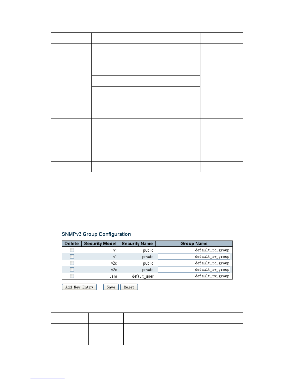
E. SNMP Group Configuration
Enter【SNMP configuration】→【Groups】navigation column, configure SNMPv3 group table on this page,
This function is used to set some of these groups and the security model, the authentication name. The Page Setup
group, as can select use group in Snmp-Access (Snmp Access Settings) page, out in option "Group Name" column,
the configuration options for the user to use Snmp access.
Interface items Introduction:
Interface items
Configuration
Introduction
Factory setting
Security Model
v1/v2c/usm
SNMP group safety mode
v1 group, v2c group,usm
group
ESMGS8-P4 Web User’s Manual
23 / 104
Security Name
Public/Private
SNMP group access
permission
public permission, private
permission, default user
permission
Group Name
0-255 byte
SNMP group name
Default_ro_group
Default_rw_group
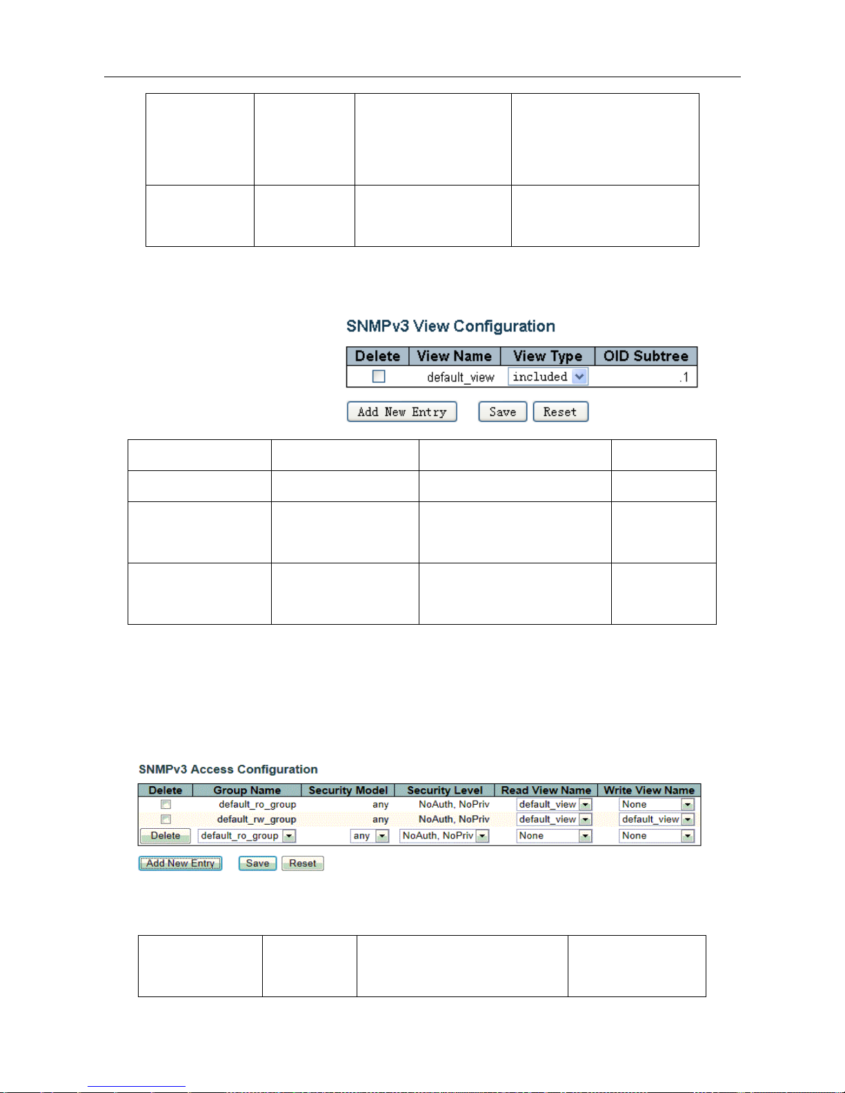
F. SNMP View Configuration
Enter 【SNMP configuration】→【Views】navigation column, Configure SNMPv3 view table on this page.
The main configuration items are: the
view name, OID subtree, include or
exclude the OID subtree.
Interface items Introduction:
Interface items
Configuration
Introduction
Factory setting
View Name
0-255 byte
View name
default_view
View Type
Included/excluded
View only included/exclude OID
subtree node
Included
OID Subtree
Use "," separated string
of numbers
OID Mark
.1
G. SNMP Access Configuration
Enter【SNMP configuration】→【Access】navigation column,Configure SNMPv3 access table on this page.
Configure when a group users access of the security mode , security levels, read-only view and read-write view. Click
[Save]to save changes. Click [Reset] to return to the default values.
Interface items Introduction:
Interface items
Configuratio
n
Introduction
Factory setting

ESMGS8-P4 Web User’s Manual
24 / 104
Group Name
0-255 byte
User group name to access
default_ro_group
default_rw_group
Security Model
any/v1/v2c/us
m
Select the security mode, any mode
/ v1 / v2c / usm for user group
any
Security Level
NoAuth ,
NoPriv
Select security level for user
group: No authentication and no
privacy
NoAuth,NoPriv
Auth,NoPriv
Authentication and no privacy.
Auth,Priv
Authentication and privacy.
Read View Name
None/view
configuration
Select the desired view name for
user
Default view
Write View Name
None/view
configuration
Select the desired write view name
for user
None
Default view
5.2.2.5 Network
A. NAS Configuration
This page allows you to configure the IEEE 802.1X and MAC-based authentication system and port settings.
The IEEE 802.1X standard defines a port-based access control procedure that prevents unauthorized access to a
network by requiring users to first submit credentials for authentication. The IEEE802.1X standard defines port-based
operation, but non-standard variants overcome security limitations as shall be explored below.MAC-based
authentication allows for authentication of more than one user on the same port, and doesn't require the user to have
special 802.1X supplicant software installed on his system. The switch uses the user's MAC address to authenticate
against the backend server. Intruders can create counterfeit MAC addresses, which makes MAC-based authentication
less secure than 802.1X authentication.
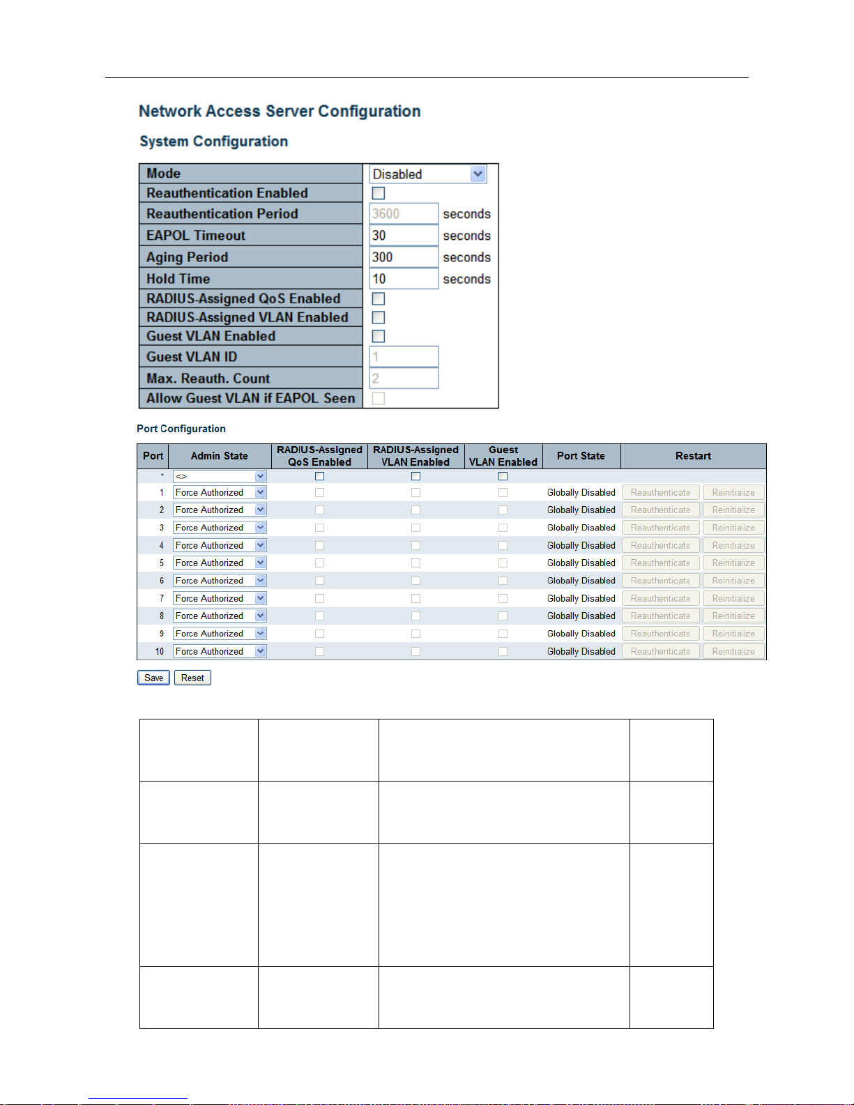
Enter【Network】→【NAS configuration】navigation column
ESMGS8-P4 Web User’s Manual
25 / 104
System configuration interface items introduction;
Interface items
Configuration
Introduction
Factory
setting
Mode
Disabled/Enabled
Indicates if NAS is globally enabled or
disabled on the switch stack.
Disabled
Reauthentication
Enabled
Check / uncheck
Once selected, after the authentication is
successful, a set time after the
Reauthentication Period, will be certified
again
uncheck
Reauthentication
Period
1-3600 second
Recertification interval
3600

ESMGS8-P4 Web User’s Manual
26 / 104
EAPOL Timeout
1-65535 second
Identity EAPOL defined time frame resend
request, and this time on the MAC-based
authentication is invalid
30
Aging Period
10-1000000
second
Certification aging time, after
authentication, within Aging Period of time
no longer detect the device, the
authentication will automatically lapse
300
Hold Time
10-1000000
second
After the authentication fails, the re-
certification intervals, during this time do
not accept the authentication request of the
terminal
10
Port configuration interface items introduction
Interface
items
Configuration
Introduction
Factory setting
Port
1-n(Number of
physical ports)
To configure the switch port number
port
1-n
Admin State
Force Authorized
In this mode, when a client is connected
to the port, the switch will automatically
send an EAPOL success frame, you can
access the network without
authentication
Force Authorized
Note: If set to a
non Force
Authorized port,
you can not open
the port Spanning
tree, and
Aggregation
functions
Force Unauthorized
In this mode, when a client is connected
to the port, the switch will automatically
send an EAPOL frame failure, any
client cant access the network
802.1X
Using 802.1X authentication mode
MAC-Based Auth.
Using MAC-Based authentication
mode
Port State
Globally Disabled
NAS all Disabled
Link Down
NAS all Enabled, but port cant

ESMGS8-P4 Web User’s Manual
27 / 104
connected
Authorized
Port operates in Force Authorized
mode, or work in only one request
mode, and the request authentication
success
Unauthorized
Port operates in Force Unauthorized
mode, or work in only one request
mode, and the request authentication
not success
X Auth/YUnauth
The port is a plurality of request mode,
X client successfully authenticates, Y
client authentication is unsuccessful
Restart
Reauthorized
Authorized buttons only when the
authentication mode in the open, while
the port state of 802.1X / MAC-Based
Auth. When it is enabled, click
Reauthorized immediately for
certification has passed recertification
Reinitialize
Reinitialize button only when the
authentication mode in the open, while
the port state of 802.1X / MAC-Based
Auth. When it is enabled, click
Reinitialize initialize the client
immediately forced to cut off the last
certification, recertification
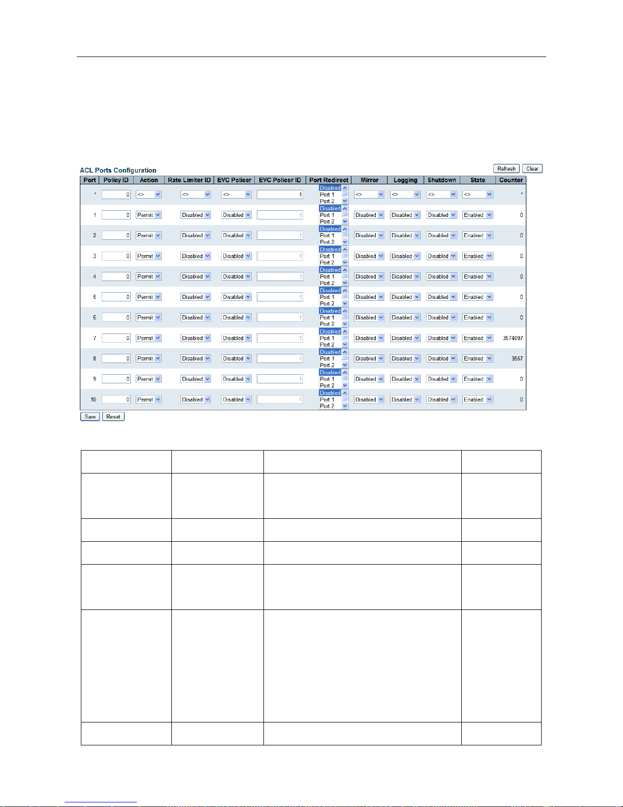
B. ACL(Access Control List )Configuration
ACL Port Configuration
Enter 【ACL configuration】→【Ports】navigation column, Configure the ACL parameters (ACE) of each
ESMGS8-P4 Web User’s Manual
28 / 104
switch port. port only can receive the frames matching ACE parameter. Also define eight per port policy number,
each policy is defined different content, you can configure the following parameters Series: Action , Permit / Deny
to specify the type of data packet forwarding, Rate Limiter ID , Port Redirect , 16 bandwidth control policies for
network security configuration page definitions; Logging (logging): Enable / Disable logging;
Interface items introduction:
Interface items
Configuration
Introduction
Factory setting
Port
1-n(Number of
physical ports)
number for Switch To configure the port
1-n
Policy ID
0-255
Select the policy to apply to this port
0
Action
Permit/Deny
Select filter out traffic is forwarded or blocked
Permit
Rate Limiter ID
Disabled/0-16
Select which rate limiter ID to apply on this
port
Disabled
Port Redirect
Disabled/port
Number
Select which port frames are redirected on.
The allowed values are Disabled or a specific
port number and it can't be set when action is
permitted. The default value is "Disabled".
Disabled
Mirror
Disabled/Enabled
Frames received on the port are mirrored or not
Disabled

ESMGS8-P4 Web User’s Manual
29 / 104
mirrored.
Logging
Disabled/Enabled
Frames received on the port are stored in the
System Log or not logged.
Disabled
Shutdown
Disabled/Enabled
If a frame is received on the port, the port will
be disabled or Enabled
State
Disabled/Enabled
When you select Enabled, when changing the
port you are using ACL user module, open
ports
When you select Disabled, when changing the
port you are using ACL User Module, shut
down the port
Enabled
Counter
Counts the number of frames that match this
ACE.
0
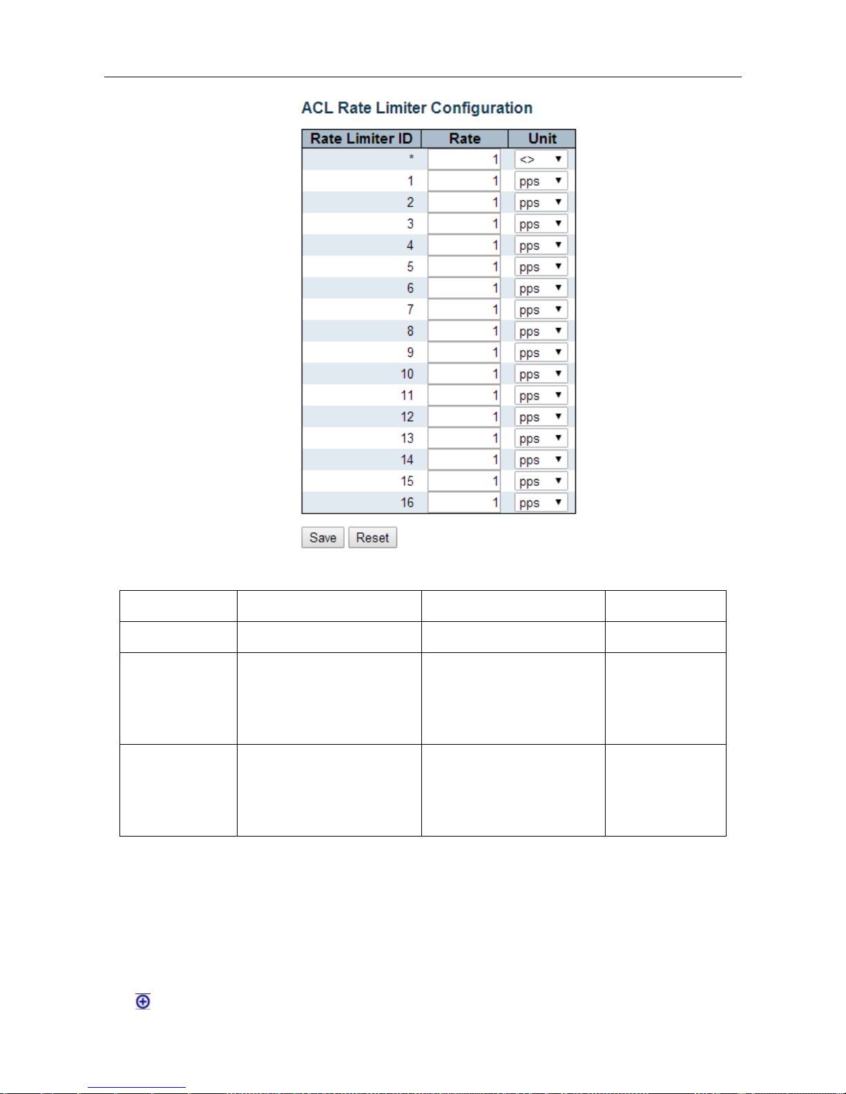
ACL Rate Limiter Configuration
Enter 【ACL configuration】→【Rate Limiters】navigation column, is the ACL rate limiter configuration of
port,The system supports 16 broadband strategy, speed range: 0-3276700 / PPS or 0,100,200,300 ... between
10000000kbps.
ESMGS8-P4 Web User’s Manual
30 / 104
Interface items introduction:
Interface items
Configuration
Introduction
Factory setting
Rate Limiter ID
1-16
ACL rate limiter ID in use
1-16
Rate
0-3276700/PPS
0,100,200,300…10000000kbp
s
Rate value configure
1
Unit
pps/kbps
Rate unit:
pps: packets / sec
Kbps: kilobytes / sec.
pps
Click [Save] button when the configuration is complete ; Click [Reset] to return to the default values.
ACL Access control List
Enter【ACL configuration】→【Access Control List】navigation column, Check system access control lists.
Click to add ACE term of list
 Loading...