

Page 1

Extended Ethernet
EE2CL
User Manual
Page 2

Extended Ethernet User Manual
TABLE OF CONTENTS
1 OVERVIEW ................................................................................. 3
1.1 I
1.2 T
NTRODUCTION
1.1.1 EE2CL ............................................................................................... 3
ECHNICAL SPECIFICATION
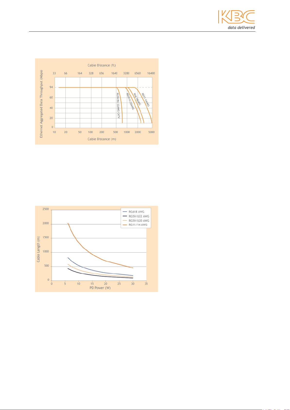
1.2.1 Data Throughput over Cable Length ...................................................... 5
1.2.2 Power Supplied over Cable Length
............................................................................................ 3
.............................................................................. 4
(1)
(PSE = 48V) ................................... 5
2 INSTALLATION ............................................................................. 6
2.1 P
2.2 C
2.3 I
2.4 C
2.5 E
2.6 P
2.7 LED S
ACKAGE CONTENTS
ONFIGURATIONS
2.2.1 Physical Connections ........................................................................... 8
NSTALLATION METHOD
2.3.1 Compact ............................................................................................ 9
2.3.2 Rack-mount ..................................................................................... 11
OAXIAL CABLE CONNECTION
THERNET CABLE CONNECTION
OWER CONNECTIONS
TATUS
............................................................................................. 13
...................................................................................... 6
......................................................................................... 7
................................................................................... 9
......................................................................... 12
....................................................................... 12
.................................................................................. 12
3 TROUBLESHOOTING .................................................................... 14
4 SYSTEM EXAMPLE ....................................................................... 15
5 DIMENSIONS ............................................................................. 16
6 WARRANTY .............................................................................. 17
6.1 W
6.2 C
6.3 FCC ....................................................................................................... 18
ARRANTY INFORMATION
LASS A
ITE ............................................................................................ 18
.............................................................................. 17
7 INSTRUCTION OF DISASSEMBLY ...................................................... 18
Manual-EE2CL_Series-Rev1304.docx
Copyright © KBC Networks Ltd. 2013 Page 2 of 19 www.kbcnetworks.com
Page 3

Extended Ethernet User Manual
1 Overview
1.1 Introduction
This manual covers the EE2CL series. These units make it possible to upgrade
installed analogue cameras to high-quality digital IP cameras without the
expense of replacing existing coaxial cabling. Units are available in an extended
temperature range, compact wall-mount format that fits inside most camera
housings and can also be mounted into a 19” rack unit.
1.1.1 EE2CL
The KBC EE2CL series is a 10/100, IEEE 802.3 af/at PoE compliant, Ethernet line
driver providing excellent repeatable performance for today’s CCTV systems. The
line driver provides connectivity for up to four, 10/100Mbps IEEE standard twisted
pair copper port over a 75 Ω coaxial cable interface allowing new IP technology to
pass over existing legacy cable up to a distance of 1.5km
Play’ and are automatically configured for straight forward installation. Maximum
data rates of up to 100Mbps are achievable.
(1)
. The units are ‘Plug and
1. Transmission distances are for indication purposes only. Actual achievable transmission distances on site will depend on cable
type installed, quality and age of installation
Manual-EE2CL_Series-Rev1304.docx
Copyright © KBC Networks Ltd. 2013 Page 3 of 19 www.kbcnetworks.com
Page 4

Extended Ethernet User Manual
(1)
1.2 Technical Specification
Standards
IEEE Standard IEEE 802.3 10BASE-T
IEEE 802.3u 100BASE-TX
IEEE 802.3x Full Duplex
IEEE 802.3af/at
RJ45 Port (Ethernet)
Data Format Ethernet
Data Rate 10/100Mbps half / full duplex auto negotiation
Coax
Transmission Distance
Cable Type RG59 or similar
Cable Impedance 75Ω
1.5km / 5000ft
Electromagnetic compatibility
Interference
Class A
Power
Input voltage
Output 48Vdc / 0.8A / Optional 0.8 – 1.3A
Power Consumption 25W
100 – 240Vac, 50 – 60Hz
Mechanical
Dimensions (Compact W x H x D)
Weight 0.12Kg / 4.2oz
75mm x 45mm x 45mm
2.95” x 1.57” x 1.57”
Environmental
Operating temperature -40°C ~ +74°C / -40° ~ +165°F
Storage temperature -40°C ~ +74°C / -40° ~ +165°F
Relative humidity 0% ~ 85% non-condensing
Mean Time Between Failure >100,000 hours
Connectors
10/100 Electrical 1 x RJ45
Coax 1 x BNC, 75Ω coaxial
Power Jack socket, 2.5mm
Manual-EE2CL_Series-Rev1304.docx
Copyright © KBC Networks Ltd. 2013 Page 4 of 19 www.kbcnetworks.com
Page 5
Extended Ethernet User Manual
1. Transmission distances supplied are for indication
purposes only. Actual achievable transmission distances on site will depend on cable type installed
, quality
1.2.1 Data Throughput over Cable Length
1.2.2 Power Supplied over Cable Length
(1)
(PSE = 48V)
and age of installation.
Manual-EE2CL_Series-Rev1304.docx
Copyright © KBC Networks Ltd. 2013 Page 5 of 19 www.kbcnetworks.com
Page 6

Extended Ethernet User Manual
2 Installation
2.1 Package Contents
EE2CL-1KT
• 2 x Extended Ethernet units
• 1 x 48Vdc, 1.25A PoE Power Supply Unit
• Quick Start Guide
EE2CL-2KT
• 3 x Extended Ethernet units
• 1 x 48Vdc, 1.25A PoE Power Supply Unit
• 1 x BNC-T Splitter Adaptor
• Quick Start Guide
EE2CL-3KT
• 4 x Extended Ethernet units
• 1 x 48Vdc, 1.25A PoE Power Supply Unit
• 1 x 1:4 BNC Splitter Adaptor
• Quick Start Guide
EE2CL-4KT
• 5 x Extended Ethernet units
• 1 x 48Vdc, 1.25A PoE Power Supply Unit
• 1 x 1:4 BNC Splitter Adaptor
• Quick Start Guide
Manual-EE2CL_Series-Rev1304.docx
Copyright © KBC Networks Ltd. 2013 Page 6 of 19 www.kbcnetworks.com
Page 7

Extended Ethernet User Manual
The following units are also available as individual units:
EE2CL-1 Extended Ethernet unit
GS60A-48-P1J 48Vdc, 1.25A PoE power supply unit
EE2CL-RK 19” high density rack system
EE-BNC4 1:4 BNC Splitter Adaptor
EE-BNC2 BNC T-Splitter
Please contact you dealer or distributor if a part is missing or damaged within 10 days of
receiving products.
2.2 Configurations
Products are available in either compact or wall-mount packages, with the following
configurations:
Product Type Compact
EE2CL
Manual-EE2CL_Series-Rev1304.docx
Copyright © KBC Networks Ltd. 2013 Page 7 of 19 www.kbcnetworks.com
Page 8

Extended Ethernet User Manual
2.2.1 Physical Connections
Extended Ethernet 200 Series
EE2CL
www.kbcnetworks.com
BNC PoE
Coax Data
Power
(no analog video)
Manual-EE2CL_Series-Rev1304.docx
Copyright © KBC Networks Ltd. 2013 Page 8 of 19 www.kbcnetworks.com
Page 9

Extended Ethernet User Manual
2.3 Installation Method
2.3.1 Compact
Basic configuration
• Remove all the packaging materials and labels.
• Choose a Master EE2CL unit; this can be any of the units purchased.
• Connect the 48Vdc power supply to the Master EE2CL unit.
• Check that the blue LEDs on both EE2CL units are lit.
Connecting the EE2CL to the camera
• Mount the EE2CL near to the IP camera.
• Connect an RJ45 cable between the camera and the RJ45 connector on the
EE2CL unit.
• Connect the coaxial cable to the BNC connector on the EE2CL unit.
• If multiple camera units connect to a single Master unit then the 1:4 BNC
Splitter Adaptor or BNC-T adapter will be required.
Note: Depending on power requirements and cable distances power for both the Master
and Slave EE2CL units and the IP cameras can be supplied from the PSU located at the
Master EE2CL unit. For high power or long distance systems, multiple PSU units will be
required; see Section 2.6.
Connecting the Master EE2CL unit at the Control Room
• Mount the Master EE2CL unit in the Control Room.
• Connect the coaxial cable to the BNC connector on the EE2CL unit.
• Connect the supplied 48Vdc PSU to the EE2CL unit
• Connect the RJ45 cable from the EE2CL unit to the Control Room
equipment.
• The green LEDs will light when a network link is established and flash to
show when data traffic is being passed.
See section 2.7 for LED status.
Note:
If two or more Master EE2CL units are connected to the same switch within a
network, the units will need to be ‘joined’ to each other. You will need a small paperclip partially straightened to join EE2CL units; this is provided with the unit.
Manual-EE2CL_Series-Rev1304.docx
Copyright © KBC Networks Ltd. 2013 Page 9 of 19 www.kbcnetworks.com
Page 10

Extended Ethernet User Manual
Joining EE2CL units
• Remove all the packaging materials and labels.
• Choose an EE2CL unit (unit ‘A’); this can be any of the units purchased.
• Using a coaxial jumper lead, connect the chosen EE2CL unit (unit ‘A’) to one
of the other units (unit ‘B’) by attaching one EE2CL unit to each end of the
coaxial cable.
• Connect the 48Vdc power supply to the EE2CL unit ‘A’.
• Check that the blue LEDs on both EE2CL units are lit.
• Wait 20 seconds. Check that the green BNC LEDs on both EE2CL are ‘off’.
Note: If either of the green BNC LEDs remains ‘on’ then that unit has already been
‘joined’ to another EE2CL unit in a different group and will need to be ‘un-joined’ before
being ‘joined’ to the new unit. See the ‘un-joining’ instructions below.
• On the EE2CL unit ‘A’ (which is connected to the PSU) use the straightened
paper-clip to depress the push button for 2 seconds. This button can be
found slightly above the PoE LED.
• The blue Power LED will flash.
• Depress the same push-button on the EE2CL unit ‘B’ for 2 seconds.
• Wait for 10 seconds. The two units will now try to establish an encrypted
communication.
• Once the blue Power LEDs return to a steady condition the units have been
joined.
• If more EE2CL units need to be ‘joined’, disconnect EE2CL unit ‘B’ from
EE2CL unit ‘A’. Connect the new ‘un-joined’ EE2CL unit ‘C’ to EE2CL unit ‘A’.
• Repeat the joining instructions until all units in the group are ‘joined’ to the
EE2CL unit ‘A’.
Un-joining EE2CL units
• Disconnect the EE2CL unit from the old network.
• Connect a 48vdc PSU to the unit.
• Wait until the green BNC LED lights.
• Using the straightened paper-clip press the small push-button located
behind and slightly above the RJ45 LED.
• Wait until the blue LED turns off.
• Release the paper-clip.
• The green BNC and RJ45 LEDs will flash and then turn off.
• The green BNC LED will then switch on for 10 seconds and then switch off.
• The units are now un-joined.
Manual-EE2CL_Series-Rev1304.docx
Copyright © KBC Networks Ltd. 2013 Page 10 of 19 www.kbcnetworks.com
Page 11

Extended Ethernet User Manual
2.3.2 Rack-mount
• Remove all packaging material.
• For each of the 1:4 BNC Splitter Adaptors, push the BNC connectors through
the holes in the front panel of the rack and secure into place. Ensure that
the BNC connectors are properly positioned so that they do not have contact
with the metal rack, before clamping into place.
• Position the PSUs into the internal PSU brackets, they do not need to be
secured in place, ensure that the slot in the front is lined up with the PSU
mains pins.
• Position the EE2CL units into the internal brackets and secure with the nuts
and bolts provided with the rack.
• Attach the 1:4 BNC Splitter Adaptor to the connector on the EE2CL unit.
• Connect the kettle lead through the front panel into the PSUs.
• Switch the power on.
See section 2.7 for LED status.
Manual-EE2CL_Series-Rev1304.docx
Copyright © KBC Networks Ltd. 2013 Page 11 of 19 www.kbcnetworks.com
Page 12

Extended Ethernet User Manual
2.4 Coaxial Cable Connection
Connect the unit’s BNC socket to the coaxial cable. When a physical link over coaxial
cable is established and the units are powered up, the green BNC LED will light to show
that the unit has detected another unit and then flash to indicate there is link activity.
See section 2.7 for complete details of LED status.
2.5 Ethernet Cable Connection
The RJ45 port is adaptive and supports auto MDI/MDI-X connection. It can be connected
by straight through or cross-over type Cat5 or Cat 6 cables. The green RJ45 LED will
light to indicate a link connection and flash to show when data traffic is being passed.
See section 2.7 for complete details of LED status.
2.6 Power Connections
This EE2CL unit must be powered by the +48Vdc, 1.25A PoE power supply, this is
supplied with the unit and is connected using a 2.1mm barrel connector.
Note: For higher power or longer distance applications please contact KBC Networks.
Depending on power requirements and cable distances, power for both the Master and
Slave EE2CL units and the IP cameras can be supplied from the PSU located at the
Master EE2CL unit.
Manual-EE2CL_Series-Rev1304.docx
Copyright © KBC Networks Ltd. 2013 Page 12 of 19 www.kbcnetworks.com
Page 13

Extended Ethernet User Manual
For long distance systems up to two PSU units can be used as shown below:
2.7 LED Status
LED Status Description
Power
BNC
PoE
ON
OFF
ON
FLASH
OFF
ON
FLASH
Power is supplied to the unit
No power to the unit
Another EE2CL unit has been detected
Link activity
No link established
Link active
Ethernet activity and joining function
OFF
No link established
Manual-EE2CL_Series-Rev1304.docx
Copyright © KBC Networks Ltd. 2013 Page 13 of 19 www.kbcnetworks.com
Page 14

Extended Ethernet User Manual
3 Troubleshooting
When the device is powered on, the blue Power LEDs will light to indicate the
presence of power. If the power LEDs flash then the power supply is cycling on and
off due to overload conditions please check to see whether there are any of the
following:
• Wiring faults
• Excessive loading
If the BNC LED does not light after a wire is connected between two EE2CL units
please check the following:
• Verify that the cable connecting the two units is not greater than 1500m in
length
If the PoE LED does not light after a cable is connected to the port please check the
following:
• Verify that the cable being used is Cat5, 5e or 6
• Check that the power to both the EE2CL and the connected device are
switched on
• Check that all cables are firmly seated
• Check that the power adaptors are all functioning
If there is no video being passed through the system, please check that you are
using a managed Ethernet switch. The EE2CL unit will block unknown multicast
packets and hence the video will be blocked. IGMP is required for a properly
configured multi-cast network.
Manual-EE2CL_Series-Rev1304.docx
Copyright © KBC Networks Ltd. 2013 Page 14 of 19 www.kbcnetworks.com
Page 15

Extended Ethernet User Manual
4 System Example
Figure 4.1 EE2CL Typical System Application
Manual-EE2CL_Series-Rev1304.docx
Copyright © KBC Networks Ltd. 2013 Page 15 of 19 www.kbcnetworks.com
Page 16

Extended Ethernet User Manual
5 Dimensions
75mm
35mm
Extended Ethernet 200 Series
EE2CL
www.kbcnetworks.com
103mm
BNC PoE
Coax Data
(no analog video)
Power
14mm
45mm
45mm
28mm
Manual-EE2CL_Series-Rev1304.docx
Copyright © KBC Networks Ltd. 2013 Page 16 of 19 www.kbcnetworks.com
Page 17

Extended Ethernet User Manual
6 Warranty
6.1 Warranty Information
KBC extends the following LIMITED WARRANTY to the original owner/purchaser of this
product as follows:
- Five years from the date of initial sale for Ethernet switches & Extended Ethernet
products.
- Two years from the date of initial sale for all wireless and other network products.
- Five years from the date of initial sale for all fiber products.
1) If, within the specified warranty period, this product, or any part or portion thereof,
shall prove upon examination by KBC, to be defective in material or workmanship,
KBC will repair or replace such part or portion at KBC’s option. The warranty period
on the repaired or replaced part or portion of this product shall be limited to the
unexpired term of the original warranty. The buyer shall be responsible for all
shipping and transportation of the product to KBC for any performance under this
warranty.
2) Conditions and Exceptions:
a) Any accident to this product, any misuse or abuse, alternation, use in modified
form, or any attempt to repair this product shall void this warranty. These
conditions to the warranty include, but are not limited to, incorrect power
connections, physical damage due to mechanical shock, exposure to moisture,
and circuit modification.
b) SHOULD THIS PRODUCT PROVE DEFECTIVE FOLLOWING PURCHASE, THE BUYER,
NOT THE MANUFACTURER, DISTRIBUTOR, OR RETAILER, ASSUMES THE ENTIRE
COST OF ALL SERVICING OR REPAIR, EXCEPT AS OTHERWISE PROVIDED BY THE
TERMS OF THIS WARRANTY.
c) FOR BREACH OF ANY WRITTEN OR IMPLIED WARRANTY ON THIS PRODUCT, THE
BUYER IS LIMITED TO THE FOLLOWING DAMAGES. (1) THE COST OF LABOR TO
REPAIR OR REPLACE DEFECTIVE PARTS OR PORTIONS OF THIS PRODUCT, AND
(2) THE COST OF THE REPAIRED OR REPLACE PARTS OR PORTIONS OF THIS
PRODUCT.
d) NO OTHER EXPRESSED OR IMPLIED WARRANTIES HAVE BEEN MADE OR WILL BE
MADE ON BEHALF OF KBC WITH RESPECT TO THE SALE, REPAIR, INSTALLATION,
OPERATION, OR REPLACEMENT OF THIS PRODUCT. KBC DISCLAIMS ANY
IMPLIED WARRANTY OF MERCHANTABILITY OF THIS PRODUCT OR ITS FITNESS
FOR ANY PURPOSE, AND THE BUYER AGREES THAT THIS PRODUCT IS SOLD “AS
IS” AND THAT THE ENTIRE RISK OF QUALITY AND PERFORMANCE OF THIS
PRODUCT IS WITH THE BUYER, EXCEPT AS OTHERWISE PROVIDED BY THE
TERMS OF THIS WARRANTY.
e) Some states/jurisdictions do not allow exclusions or limitations of incidental or
consequential damages, or limitations on how long an implied warranty lasts, so
the above exclusions or limitations may not apply to you.
f) If you do not wish to be bound by any of the provisions in this warranty, please
return the product(s) immediately.
3) Contact your dealer regarding return authorizations for out of warranty repairs and
any further product information.
This warranty does not apply in Australia.
Manual-EE2CL_Series-Rev1304.docx
Copyright © KBC Networks Ltd. 2013 Page 17 of 19 www.kbcnetworks.com
Page 18

Extended Ethernet User Manual
6.2 Class A ITE
This is a Class A product. In a domestic environment this product may cause radio
interference in which case the user may be required to take adequate measures.
6.3 FCC
This equipment has been tested and found to comply with the limits for a Class A digital
device, pursuant to Part 15 of the FCC Rules. These limits are designed to provide
reasonable protection against harmful interference when the equipment is operated in a
commercial environment. This equipment generates uses and can radiate radio
frequency energy and, if not installed and used in accordance with the instruction
manual, may cause harmful Interference to radio communications. Operation of this
equipment in a residential area is likely to cause harmful interference in which case the
user will be required to correct the interference at this own expense.
7 Instruction of Disassembly
Instruction of Disassembly of KBC Product
(For EU Directive 2002/95/EEC-WEEE)
Tools required:
• No. 1 Phillips screwdriver
• No. 2 Phillips screwdriver
Steps for disassembly:
1. Remove tightening screws of box cover.
2. Remove cover plate.
3. Remove tightening screws for printed circuit board (PCB).
4. Take out all PCBs.
Notice: When a product reaches the end of its life – return to KBC.
Manual-EE2CL_Series-Rev1304.docx
Copyright © KBC Networks Ltd. 2013 Page 18 of 19 www.kbcnetworks.com
Page 19

data delivered
KBC Networks
25691 Atlantic Ocean Drive
Suite 3B
Lake Forest, CA 92630
U.S.A
Americas
Phone: 1-949-297-4930
Fax: 1-949-297-4933
KBC Networks Ltd., EMEA
KBC Networks Ltd.
Barham Court
Teston, Maidstone
Kent, ME18 5BZ
United Kingdom
Phone: +44(0)1622 618787
Fax: +44(0)20 7100 8147
Email:
Web: www.kbcnetworks.com
info@kbcnetworks.com
 Loading...