

KBC BAH-1010AVS Instruction Manual
MACHINERY
DIVlSlON
5465
16
MIL.F
ROAD
STERLING
HEIGHTS,
MI
4831
4
PHONE:
(536)
731
-36CO
1-800-860-1
740
<g{jJ@*&$m;im#
MX:
----
?i
(586)
731
-3464 * 1
-800-862-1
740
MODEL BAH-I OIOAVS
BANDSAW
THANK YOU FOR PURCHASING WlTH KBC MACHINERY. ALL KBC
MACHINES ARE BACKED BY OUR
1
YEAR PARTS REPLACEMENT
WARRANTY. WHEN USED AS INTENDED, AND WlTH PROPER
MAINTENANCE
THIS MACHINE WILL PROVIDE YOU WlTH YEARS OF
TROUBLE-FREE SERVICE. IF YOU NEED PARTS SIMPLY
FILL OUT
THE PARTS REQUEST FORM, AND FAX OR E-MAIL YOUR REQUEST.
ALL OTHER QUESTIONS PLEASE CONTACT US
@
:
KBC
MACHINERY
6465 18
MILE ROAD
STERLING
HEIGHTS,MI
48314
PH
(800) 860-1740
FAX
(800) 862-1740
www.
KBCTOOLS.
COM

Instruction
Manual
Automatic Horizontal
I
NOTICE:
Please read this instruction manual carefully to obtain a
thorough knowledge of installation, operation and maintenance. Please
remember the following: Correctly operate the machine as described in the
manual to prevent accident. Do not operate the machine by guesswork. We
suggest you always keep manual at hand and refer to
it
whenever you are
I
I
not sure of how to perform any procedures for
AH-101OJAY.
I
Instruction Manual:
AH-lO1OJAY
Horizontal Bandsaw
Ver.
2
--
Date
:
1211 711998
FROM THE MANCJFACTURER
You have just purchased a machine manufactured by the COSEN Machinery
Industrial Co., Ltd. We'd like to take this chance to express our appreciation to you for
being our valued customer. Any comment
From you will help us to design a better
product or provide a
better service for you.
The band saw machine will provide low cost cutting accuracy for many years
ifthe
procedures for installation, operation, maintenance and troubleshooting are followed.
However, if there are questions, please contact our agent or our factory for the nearest
,
service or sales representative.
Enough, already.
I
hope you find
COSEN
as incredibly smart as I do.
If
you have
any suggestions for improvement, please tell us, we
will
appreciate your help.
"again"
Thank you so much for purchasing
COSEN
band saw machine.
President
\
R
COSEN
Machinery Indus ial Co., Ltd.
YC2
Richard
is
nynam:
Taadirgis
nygane
Bmenithm:
Andbeapofessw.
SAFETY
-
1. Know your band saw. Read the operator's manual carefully.
Learn
the operation, application and
limitation. Realize the specific potential hazards peculiar to this band saw.
-
2. Use recommended accessories. Improper accessories may be hazardous.
3.
Wear
proper apparel.
4. Keep unnecessary people away.
*
Do not overreach or stand on tool.
-
5.
Avoid dangerous environment. Do not use band saw in damp or wet locations. Keep work area
well illuminated.
-
6. Keep work
area
clean. Cluttered and slippery floors invite accidents.
7. Remove adjusting keys and wrenches from band saw before turning on power.
8. Avoid accidental starting. Make sure switch is off before plugging in power cord.
-
9. Do not force band saw. It is safer to operate with the cutting rate for which it was designed.
10.
Never hand hold the material with saw in horizontal position. Always use the vise, and clamp
-
secure1 y.
1 1.
Keep belt guard and wheel covers in place and in working order.
12. When a workpiece is too long or heavy, support it from the floor.
13.
Always remember to switch off the machine when the work is completed.
14. Disconnect power cord before adjusting,
servicing and changing blade.
15.
Check damaged parts. Before further use of the tool, a guard or other parts that is damaged should
-
be carefully checked. To assure that it will operate properly and perform its intended function.
16.
Moving parts should keep in an alignment and binding. Check for breakage, mounting and any
other conditions that may affect its operation. Any damaged part or guard should
be
properly
.
-
repaired or replaced.
17. Use a sharp blade and keep tool clean for best and safest performance.
-.
18. Safety is a combination of operator's common sense and alertness at
all
times when the saw is
functioning.
19. Maintaining the band saw in top condition is essential for safety.
SAFETY RULES
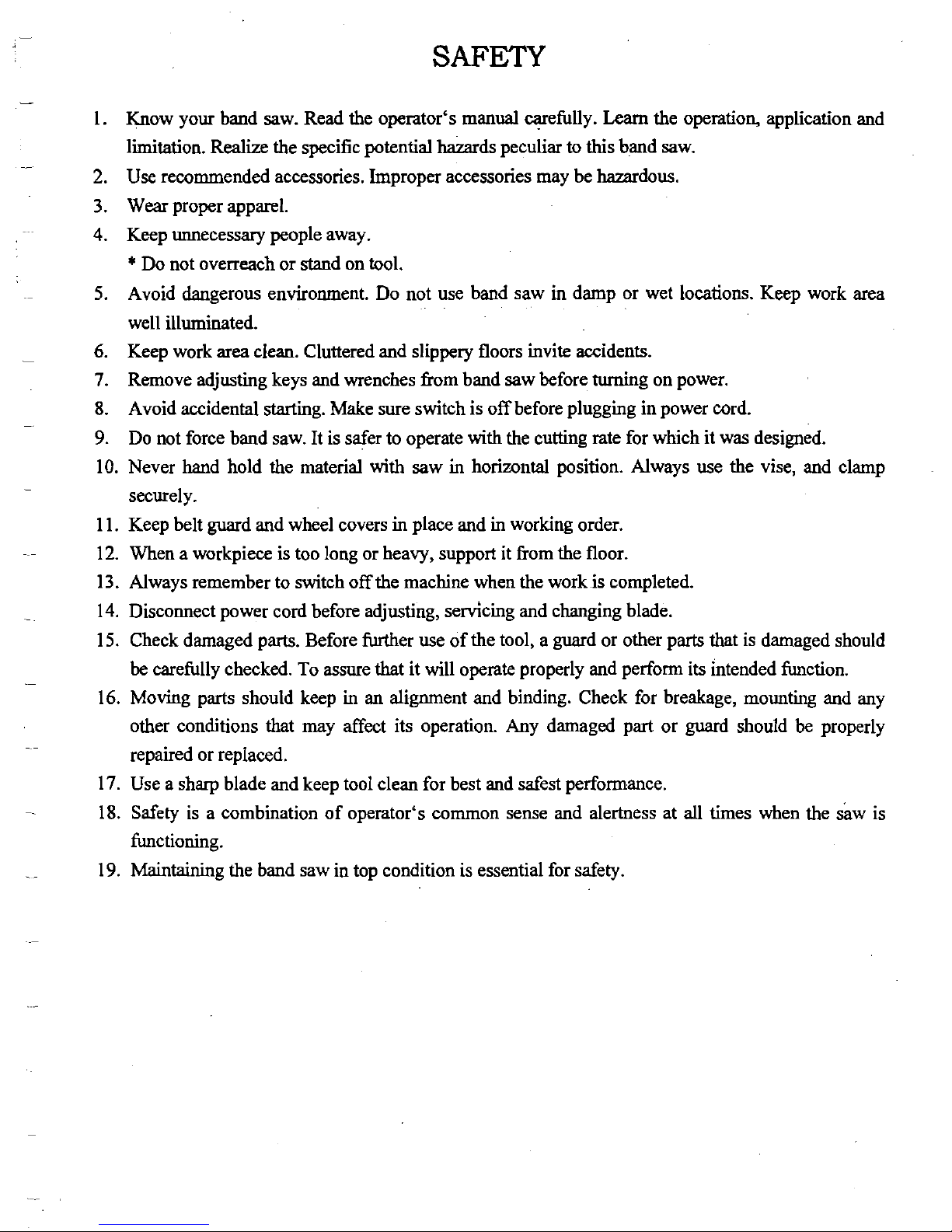
Never wear gloves loose clothing when operating the machine. They may cause danger
if
they are
caught
in
a running machine.
Be sure to
confi
that the area around the machine is cleared of people and obstacles every time
before starting the machine or operation.
I
Use a water-soluble cutting fluid on this machine. Oil-based cutting fluids may emit smoke or
catch
1
.
fue, depending on the condition of their use.
W
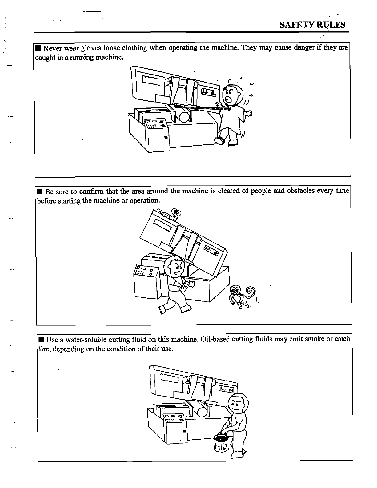
Never
try
to adjust the wire
brush
on the
saw
blade or remove chips when the saw blade
is
running.
It
is
dangerous if
hands
or clothing are caught by the
running
blade.
W
Never cut carbon or
any
other material that produces
and
disperses explosive dust on this machine.
Sparks
from
motors
and
other machine parts may ignite
and
explode the air-borne dust
The
machine
needs special measures for cutting explosive materials.
Stop
the
saw
blade before you clean the machine. It
is
dangerous
if
hands
or clothing are caught by
the
running
blade.
----
SAFETY
RWES
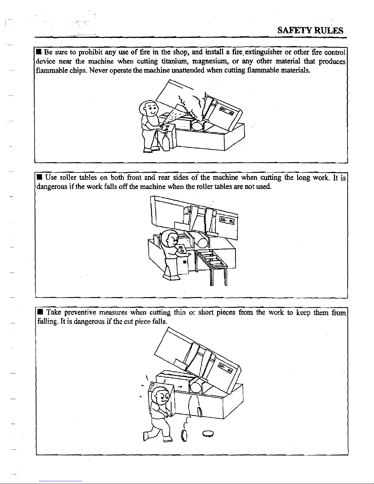
Be
sure
to prohibit
any
use
of fire
in
the shop, and
install
a
fire-extinguisher or other fire
control
device
near the machine when cutting
titanium,
magnesium, or
any
other material that produces
flammable chips. Never operate the machine unattended when cutting flammable materials.
Use
roller tables on both front and rear sides of the machine when cutting the long work. It is
dangerous if the work falls off the machine when the roller tables are
not
used.
Take preventive measures when cutting thin or short pieces from the work to keep them
from
falling. It is dangerous if
the
cut piece falls.
SAFETY
RULES
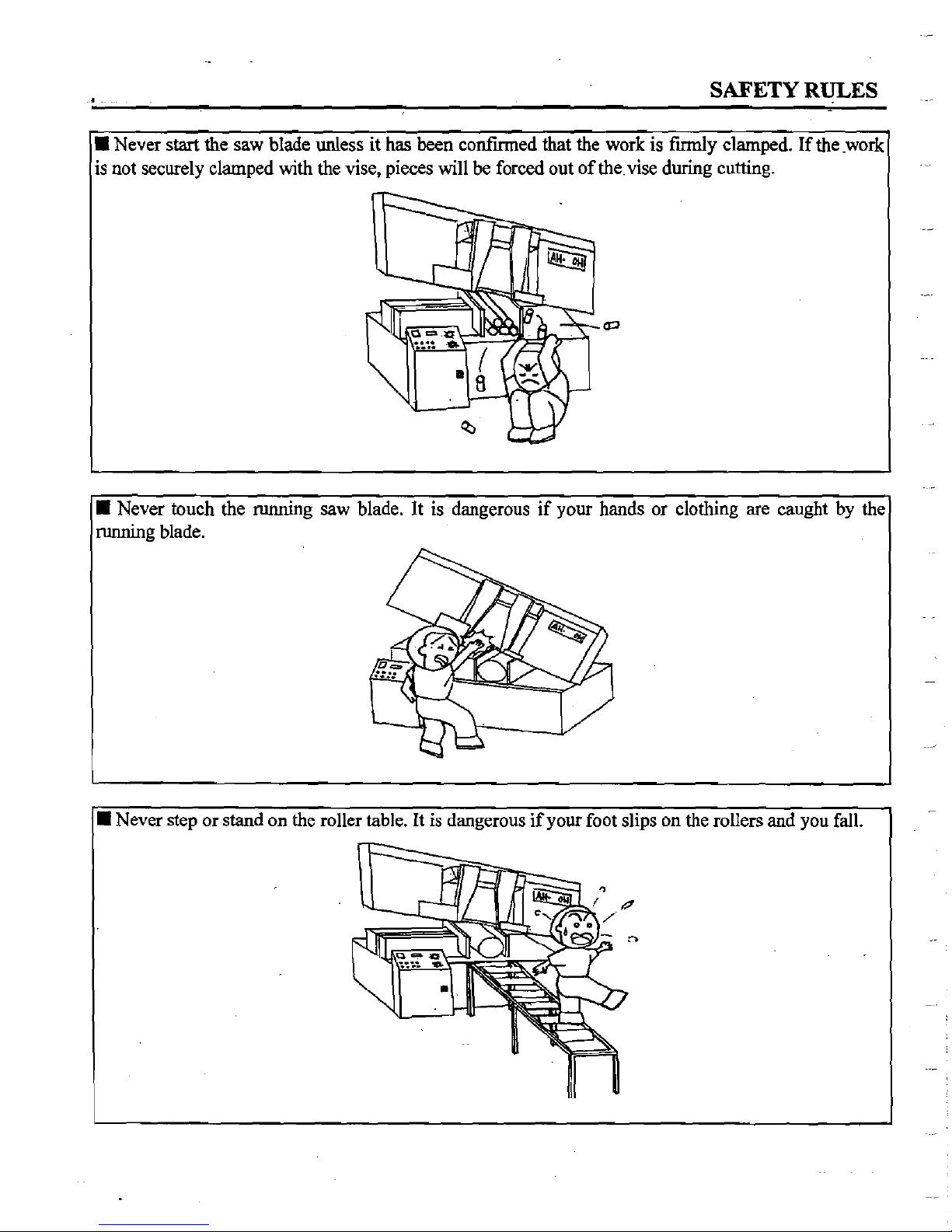
Never start the saw blade unless
it
has
been confied that the work
is
fumly clamped.
If
thework
is
not securely clamped with the vise, pieces will be forced out of the vise during cutting.
w
Never touch the running saw blade. It is dangerous if your hands or clothing are caught by the
running blade.
Never step or stand on the roller table. It is dangerous if your foot slips on the rollers and you
fall.
SAFETY RWES
0
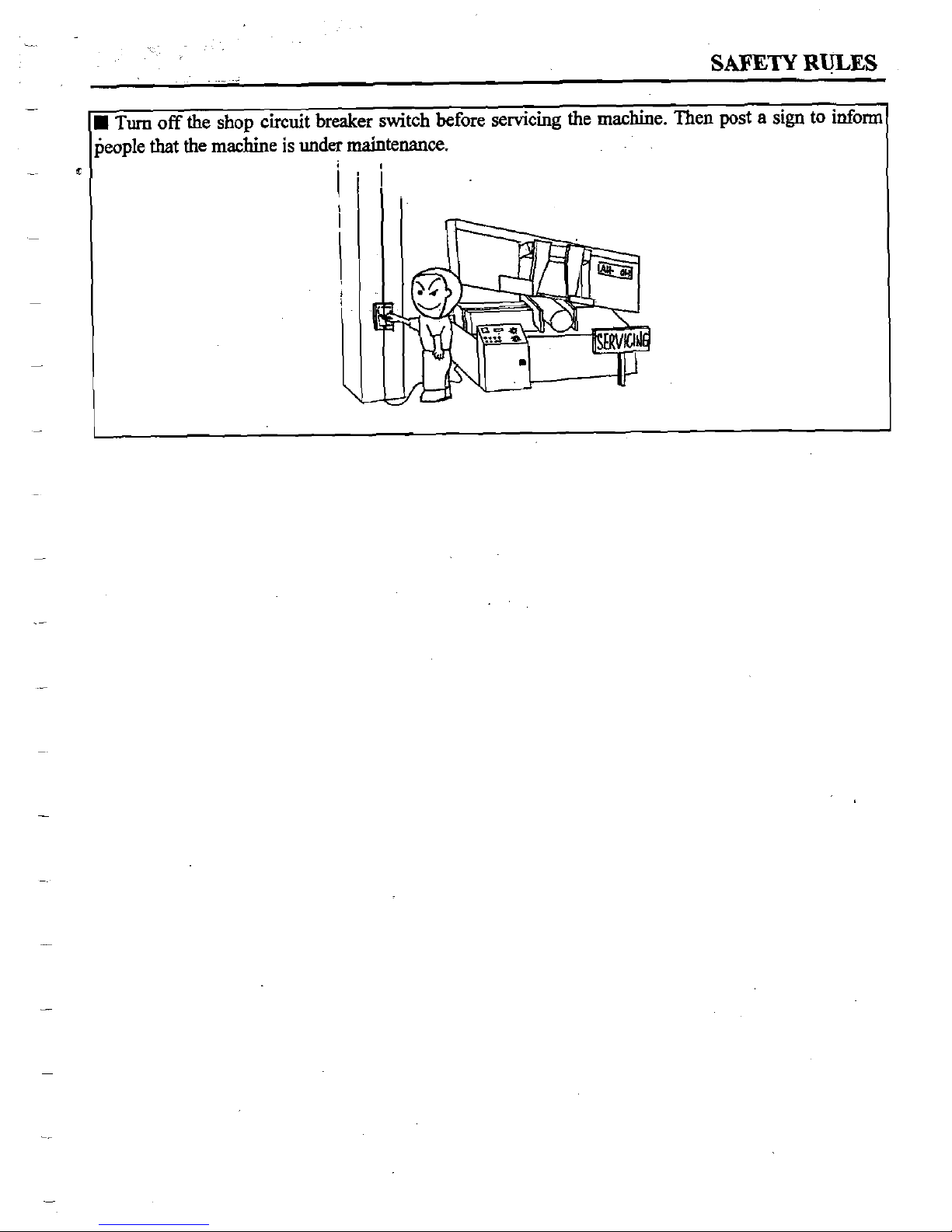
Turn
off
the
shop
circuit breaker switch before servicing the machine. Then
post
a
sign
to inform
people
that
the machine
is
under
maintenance.
Emotion
Foreward
Safety
Rules
Section
1
GENERAL INFORMATION
1-1 - 1-5
1.1
INTRODUCTION
1-1
1.2
EQUIPMENT DESCRIPTION
1-2
1.3
SPECIFICATIONS
1-3
1.4
IDENTIFICATION
AND
TERMINOLOGY OF
THE
MACHINE
1-4
1.5
SYFETY DEVICES
AND
SAFETY GUARDS
1-6
1.6
NOISE LEVEL
1-8
2.
MOVING AND INSTALLATION
2-1 - 2-5
2.1
INTRODUCTION
2- 1
2.2
MOVING OF THE MACHINE
2-1
2.3
INSTALLATION OF THE MACHINE
2-4
2.4
WORKING CONDITIONS
2-10
3.
OPERATING INSTRUCTION
3-1 -3-12
3.1
SAFETY PRECAUTIONS
3- 1
3.2
PREPARATION FOR USE
3-2
3.3
CONTROLPANEL
3-3
3.4
CHECKLIST BEFORE OPERATING
3-15
3.5
HOW TO LOAD THE WORKPIECE
3-15
3.6
TEST RUN THE MCHINE
3-16
3.7
HOW TO SELECT
AND
REPLACE THE SAW BLADE
3-18
3.8
PROCEDURES TO STOP AN OPERATING PROCESS
3-21
4.
ELECTRICAL SYSTEM
4-1 - 4-2
5.
HYDRAULIC SYSTEM
5-1 - 5-2
5.1
INTRODUCTION
5-
I
5.2
THE HYDRAULIC CIRCUIT
52
5.3
THE
LAYOUT OF
THE
HYDRAULIC SYSTEM
5-3
6.
BAND SAW CUTTING -A PRACTICAL GUIDE
6-1
-6-5
6.1
INTRODUCTION
6-
1
6.2
BAM) SAW BLADE SELECTION
6-1
6.3
SOME SAWING PRACTICES 6-3
7.
MAINTENANCE
7-1
-
7-3
7.1
MAINTENANCE SCHEDULE
7-
1
7.2
STORAGE CONDITIONS OF THE MACHINE 7-2
7.3
DISPOSAL OF
THE
MACHINE
7-2
8.
SYSTEMS TROUBLE SHOOTING
8-1
-8-4
8.1
INTRODUCTION
8-
I
8.2
GENERAL TROUBLES AND SOLUTIONS
8-2
8.3
MOTOR TROUBLES AND SOLUTIONS
8-3
8.4
BLADE TROUBLES
AND
SOLUTIONS
8-4
9.
PARTS LIST
9-1 - 9-11
CHART 1 SAW BOW
9-
I
CHART 2 BLADE GUIDE ARMS
9-4
CHART 3 BED ASSEMBLY
9-6
CHART 4 BASE ASSEMBL
9-8
CHART 5 HYDRAULIC SYSTEM
9-II
APPENDIX
A.
Specifications of the Machine
.
appendk-
I
B.
Foundation Diagram appendii-
I1
C.
Accessories of the Machine appendix-ID
D. Maintenance Schedule appendix-N
GENERAL
INFORMATION
Section
1
SECTION
1
GENERAL
INFORMATION
1.1
INTRODUCTION
COSEN is one of the bandsaw makers who have manufactured the machines for more
than
two decades and COSEN is devoted to the research and development of advanced technology to
improve the quality and safety of bandsaws.
Almost all of the countries lay emphasis on the safety design concept in order to envisage
the coming next century.
As
a
machinery industrial company, COSEN continues to follow this
central concept of excluding all sources of possible injury or damage to health
ffom bandsaw
operation.
~owevei, the customer's confidence depends not only on the quality of the products and
the reputation of the market but also the certification of a notified body, although COSEN believed that
the former two terms
had
been well achieved for her products.
Recently one thing
happened and it could
be
considered as a great milestone for COSEN
to get into the-state-of-the-art technology, that
was,
after the outside assistance of a notified body,
AMTRI
VERITAS
Limited, COSEN
had
obtained the
CE DESIGNATION,
a national standard
which was approved by ECS (European Committee for Standardization).
COSEN metal cutting
bandsaw is an ideal tool for the machine shop, metal fabricating
shop, school and limited
run
production work.
Your machine is designed to cut the metal materials and possesses the following advantages,
Machinery or each component can be handled safely.
Machinery or each component can be easily removed, replaced or operated
by
the user.
Machinery or each component has passed the strictly testing (Council Directive on the
approximation of the laws of the Member States relating to
Mach'iety)
This manual is divided into ten sections including shipping, handling, unpacking,
initial checkout, operation, and maintenance. Each section covers a specific aspect of the machine.
GENERAL
INFORMATION
Section
1
.
1.2
EQUIPMENT DESCRIPTION
Your machine is designed under the guideline of low cost and high performance. The features are
described below,
Straight cutting with easy set-up and high precision positioning.
-
Heavy duty motor, rigid reducer and variable drive assembly with excellent mechanical
design feature the increasing demand for production cutting.
Also applicable for structural steel processing, such as pipe, channel, H beam, angle and
bar stock with automatic roller feeding.
Amply-dimensioned machine base and saw frame allows easy operating.
Centralized Knee-type front control box (main electrical box).
-
The blade guidance mounted with bearings and carbide faced inserts maintains
the stability of machining and
reduces the vibrations of cutting. This produces high
degree of cutting accuracy and a long blade life.
.-
The cast iron dovetail slide guide and guide arms construct the unique characteristics
of rigidity and stability.
This machine is designed to prevent the operator from accidental access to moving
elements during operation by using safety
guards.
If the saw blade is broken during the cutting period, the machine will stop automatically.
The life of the machine is approximately
10
years if it is operated under normal
operating conditions and maintenance,
8
hours
X
5
days
X
52
weeks
X
10
years
=
20,800
hours
Lp-
c
GENERAL
INE'ORMATION
Section
1
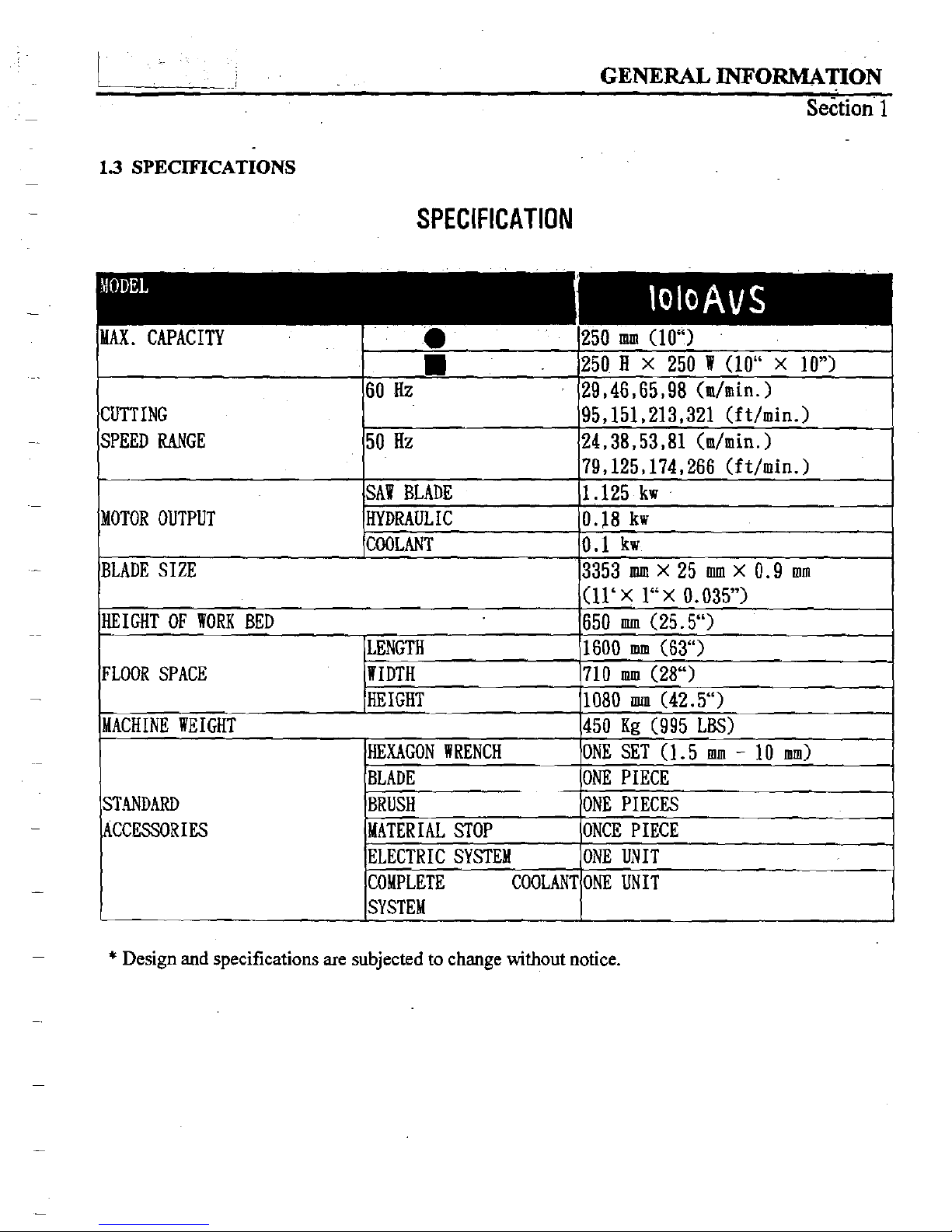
1.3
SPECIFICATIONS
SPECIFICATION
MAX.
CAPACITY 250
mn
(10")
250
B
X
250
W
(10"
X
10")
60
Hz
29,46,65,98
(&in.)
CUTTING
SPEED RANGE
ELECTRIC SYSTEM
COlPLETE COOLANT ONE UNIT
*
Design
and
specifications are subjected to change without notice.
1
-
A
GENERAL
INFORMATION
Section
1
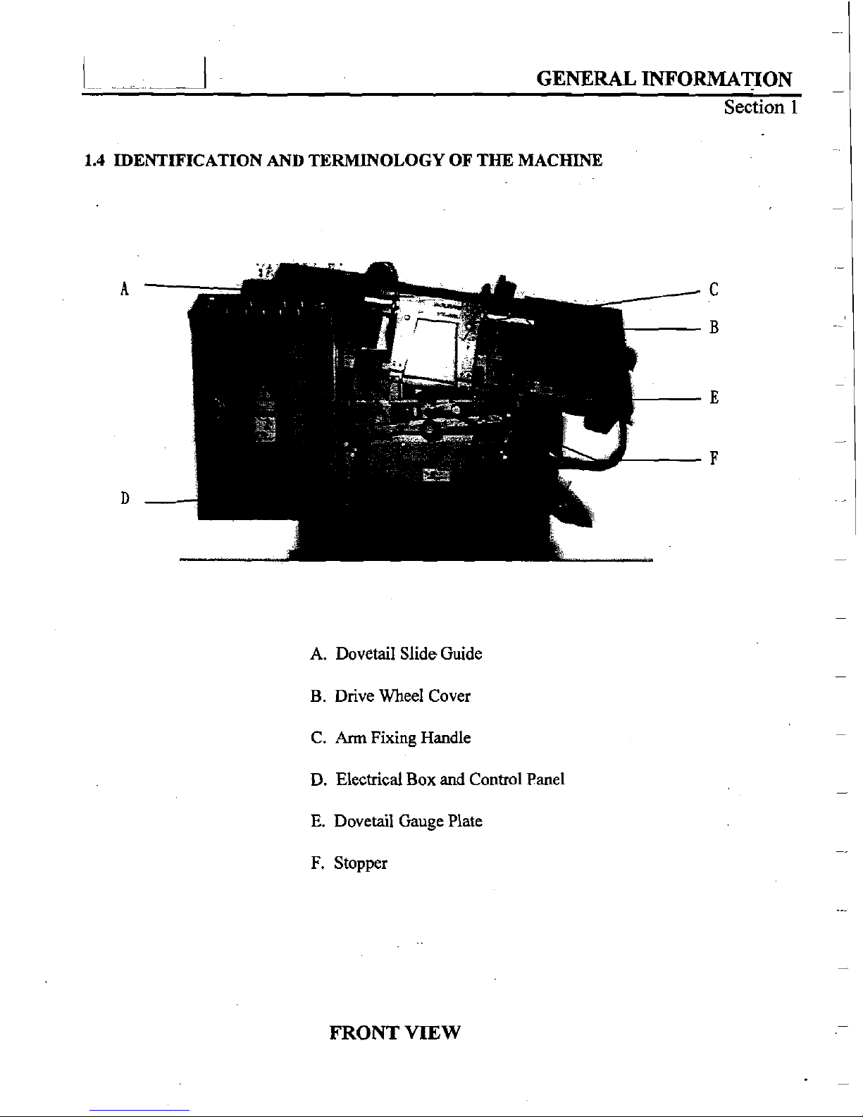
1.4
IDENTIFICATION AND TERMLNOLOGY OF THE
MACHINE
A.
Dovetail Slide Guide
B. Drive Wheel Cover
C.
Ann
Fixing
Handle
D.
Electrical Box
and
Control Panel
E. Dovetail Gauge Plate
F.
Stopper
FRONT
VIEW
1.
--
A
GENERAL
INFORMATION
Section
1
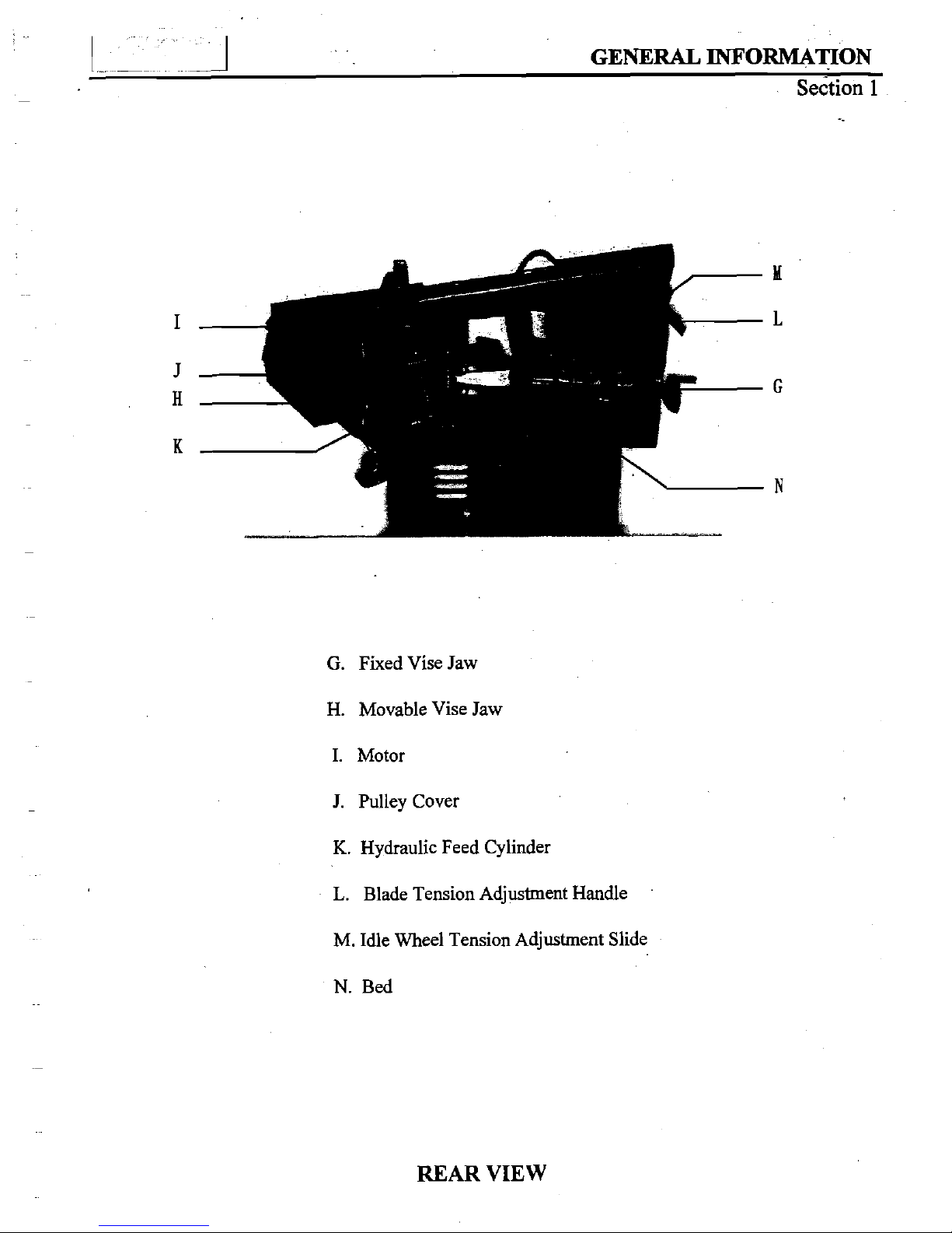
G.
Fixed Vise Jaw
H. Movable Vise Jaw
I. Motor
J.
Pulley Cover
K.
Hydraulic Feed Cylinder
L.
Blade Tension Adjustment Handle
M. Idle Wheel Tension Adjustment Slide
N.
Bed
REAR
VIEW
~
~ ~
I
GENERAL
INFORMATION
Section
1
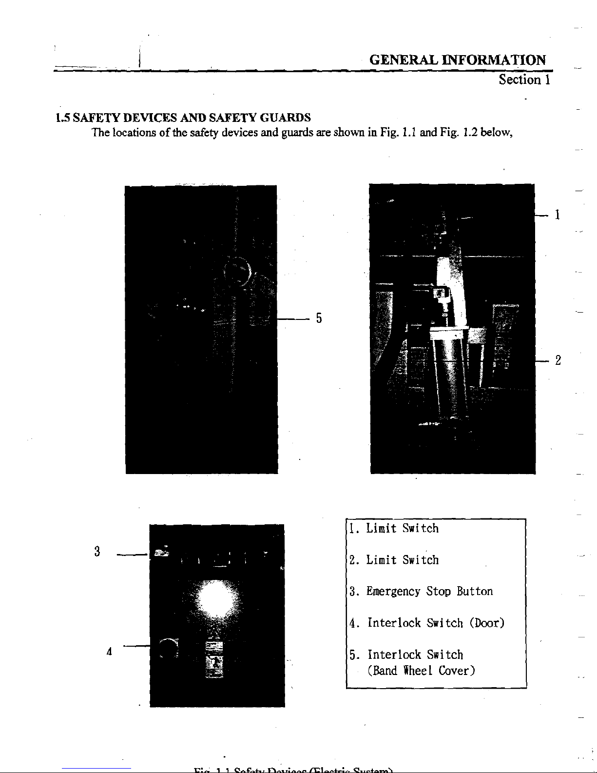
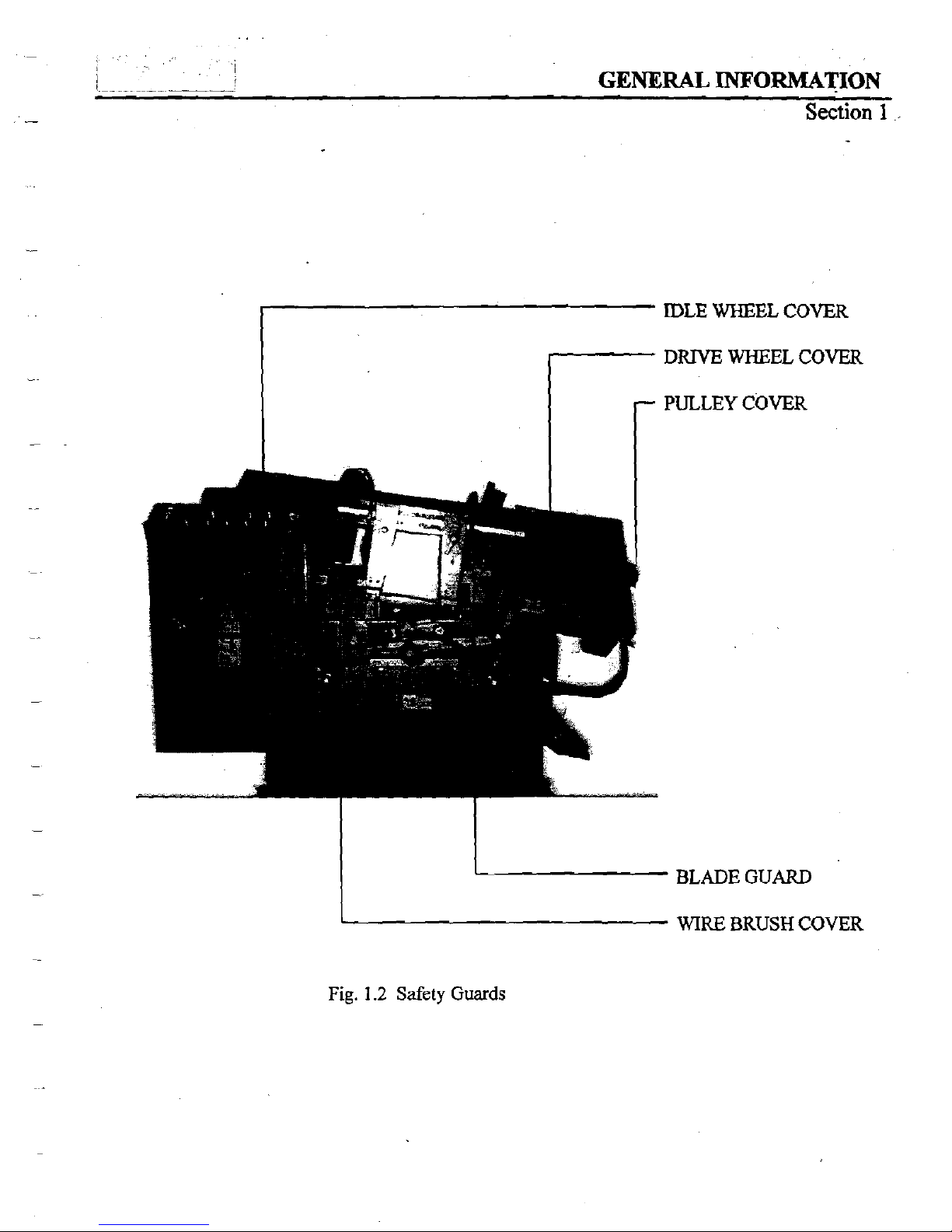
1.5
SAFETY DEVICES
AND
SAFETY GUARDS
The
locations of the
safety
devices and
guards
are
shown
in
Fig.
1.1
and
Fig.
1.2
below,
1.
Limit Switch
2.
Limit switch
3.
Emergency Stop Button
4.
Interlock Switch (Door)
5.
Interlock Switch
(Band
Wheel Cover)
I
(
-_
..
.
-
-
__
-
_
GENERAL
INFORMATION
Section
1
IDLE WHEEL
COVER
DRNE
WHEEL
COVER
r
PULLEY
COVER
BLADEGUARD
WIRE
BRUSH
COVER
Fig.
1.2
Safety
Guards
L
~
1
GENERAL
INFORMATION
--
Section
1
1.6
NOISE
LEVEL
Noise is a very important environmental concern at the work site.
Excessive exposure to high levels of noise may cause
injury
to the hearing, but the
sensitivity to
hearing
loss varies between individuals and must
be
taken into account in
specifying an allowable limit for noise exposure.
-
A level of
90
dBA
is widely accepted as a criterion for 8Wday exposure to steady-state
broad-band noise.
The unprotected ear should not be exposed to noise levels higher than 120 dBA.
The
noise of
the
machine comes from the following sources,
1.
Saw blade during cutting
2.
Wire brush unit
3.
Chip conveyor unit
4.
Speed reducer
5.
Hydraulic motor /
pump
6.
Belt transmissions variable speed motors
7.
Blade motor
8. Drive wheels
9.
Parts
not secured tightly causing mechanical vibration
The noise level of this machine has passed noise testing criterion (under 70
dBA).
Please refer to the system troubleshooting in section 10 if abnormal noise occurs.
!
...~~
~
I
MOVING
AND
INSTALLAPON
Section
2
SECTION
2
MOVING
AND
INSTALLATION
2.1
INTRODUCTION
Your machine is composed of three
main
systems, named
Mechanical System,
Hydraulic System,
and
Electrical Control System.
Please read the manual carefully to obtain a thorough knowledge of the machine and i&
moving & installation. Correctly operate the machine as described
in
the manual to prevent personal
injuries and machine damage.
Do not operate the machine by guesswork. Keep
this
manual at hand and refer to it
whenever you are not sure of how to perform any of the procedures.
2.2
MOVING OF
THE
MACHINE
As far
as
the moving of the machine is concerned, please follow the
carrying
and
cleaning
method to keep your machine in the best working condition. You
can
choose any one method
as
following to move your machine:
A.
CARRYING:
1.
Use crane to place
Cany the machine to
its
location by using a crane and a wire rope sling that can fully
withstand the weight of the machine( your machine weight about
640
Kg). Apply the wire rope sling to
the
liftiig hooks at the rear of the front vise slide and to the rear end of the machine. Slowly lift the
machine while takiig care so that the machine is not shocked and that the wire rope does not
Mere
with the saw-head.
1
-2
MOVING
AND
INSTALLATION
Section
2
n
J*
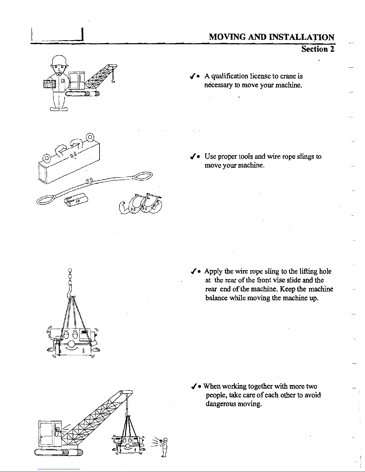
A
qualification license to crane is
necessary to move your machine.
J=
Use proper tools and
wire
rope slings to
move your machine.
J=
Apply the wire rope sling
to
the liftiig hole
at the
rear
of the fiont vise slide
and
the
rear
end
of the machine. Keep the machine
balance
while moving the
machine
up.
J=
When working together with more two
people,
take
care of each other to avoid
dangerous moving.
.~
.
'
,
.
.
~.~~
~
MOVING
AND
INSTALLATION
-
&-tion
2
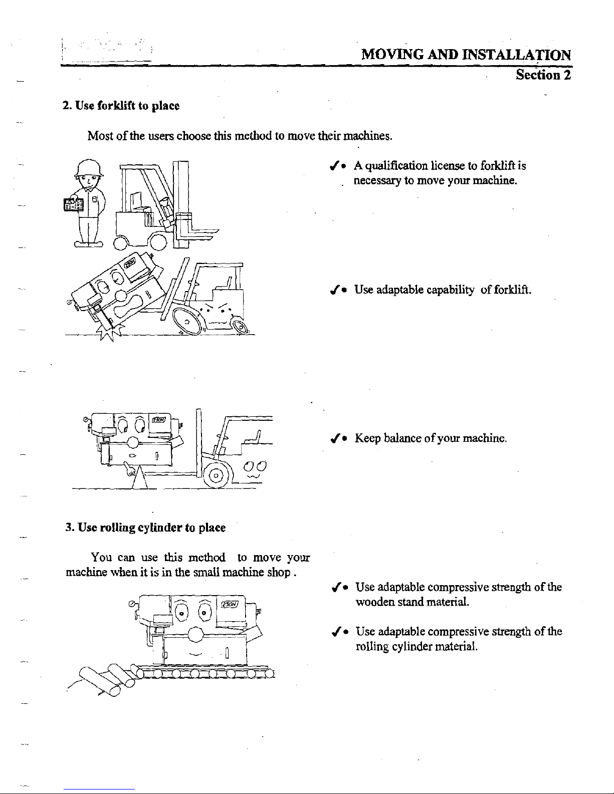
2.
Use forklift
to
place
Most of the users choose this method to move their machines.
J-
A
qualification license to forklift
is
necessary to move yout machine.
J*
Use adaptable capability of forklift.
J*
Keep balance of your machine.
3.
Use
rolling
cylinder
to
place
You can use
this
method
to
move your
machine when it is
in
the small machine shop
.
J-
Use ada~table com~ressive
strenath
of the
-
wooden stand material.
J
Use adaptable compressive strength of the
rolling cylinder material.
1
MOVING
AND
INSTALLATION
Section
2
B.
CLEANING
After the machine has been spotted on the designated position, remove the rust-preventive
grease with wiping cloth dampened with cleaning oil or kerosene. Apply machine oil to the machine
surfaces that are susceptible to
&sting.
u
Do not remove the rust-preventive grease with a scraper or the like. Do not wipe the painted
surfaces
with
solvent.
-
2.3
INSTALLATION OF THE MACHINE
2.3.1
Safety Precautions
Surroundings
J
Keep the machine away from the sun light.
J
Keep the temperature of the surroundings at
540".
J
Keep the humidity of the surrondings at
30%-95"
(without condensation) to
avoid dew on electric installation and machine.
J
Keep enough space between your machine and others machines to avoid the vibration
interfering to each other.
J
Do not install your machine on
an
uneven ground foundation.
-
J
Keep your machine away from the water or heavy dust.
Power Supply
J
Supply voltage:
90
%-
110
%
of nominal supply voltage.
J
Source frequency:
99
%-
101
%
of nominal fkquency.
J
Do not
use
the same power supply together
with
electric spark machining, electric welder.
to
avoid unstable voltage.
J
The independent and direct power supply is a suggestion.
J*
Use correct capacity of electric power supply.
-Limit the supply voltage variations to within
+
10%
J*
Earth
the machine properly with an independent wire.
2.3.2
Initial Inspection
1.
Check the model of your machine and the instruction manual.
2.
Check the equipment or tools being furnished.
3.
Check the outlook of your machine
to
make sure that your machine was shipped or
transportation in a good condition.
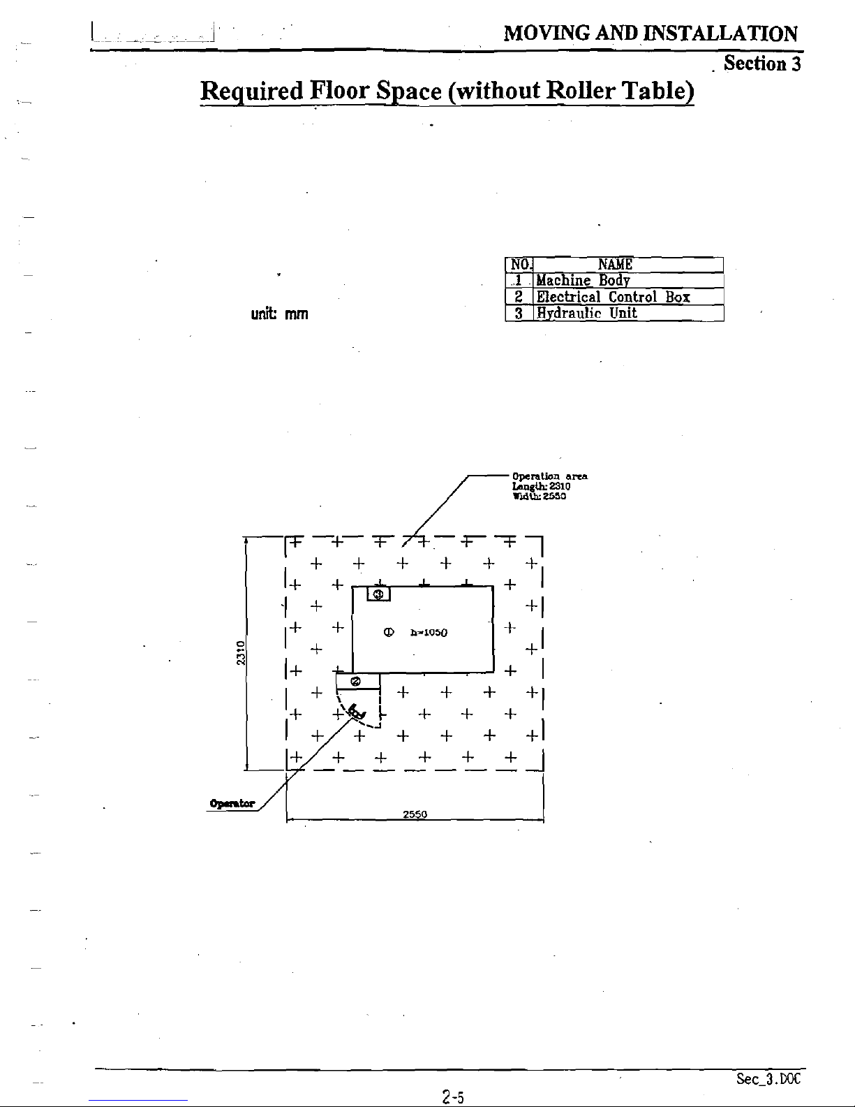
23.3
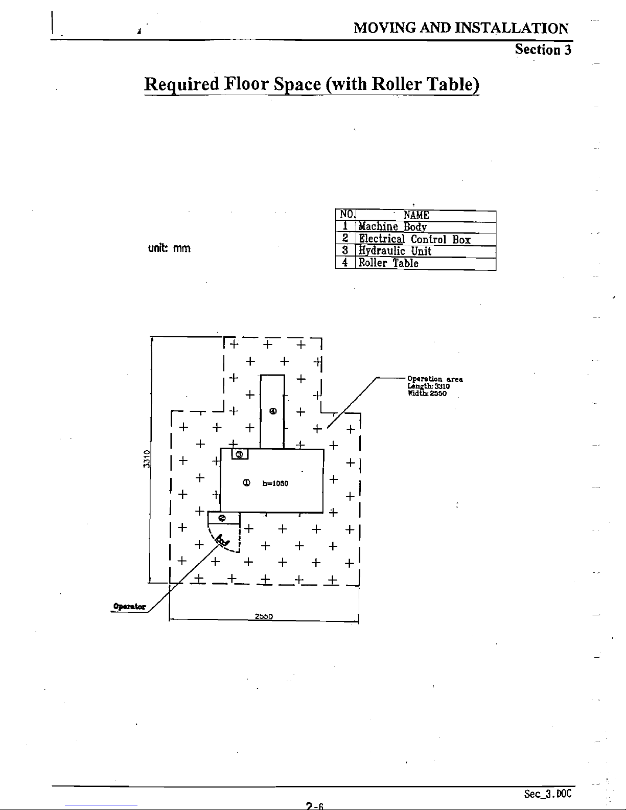
Space Required
Keep enough spaces for material
loading and unloading, operation, inspection and
maintenance of the machine as the following figures,
.
1
1
-
--
--J
MOVING
AM)
INSTALLATION
-
.
Section
3
Reauired Floor S~ace (without Roller Table)
unit:
mrn
/-
Operation
ama
LangUL.2310
Trd&
2550
1
A
MOVING
AND
INSTALLATION
Section
3
Reauired Floor S~ace (with Roller Table)
unit:
mrn
.
-
Sec
3.mc
 Loading...