


3U Chassis Transceiver
User Manual


3U Chassis Transceiver User Manual
Table of Contents
0. Product Type...................................................................................................1
1. Overview ..........................................................................................................1
1.1 Introduction...............................................................................................................1
1.2 Technical Specification.............................................................................................2
2. Package Contents..........................................................................................2
3. Transmitter Enclosure ..................................................................................3
3.1 Video Transmitter.....................................................................................................3
3.1.1 8 Bit Video Transmitter................................................................................3
3.1.2 10 Bit Video Transmitter..............................................................................4
3.2 Video Multiplexer Transmitter..................................................................................4
3.3 Video Transmitter with return Data.........................................................................6
3.3.1 8 Bit Video Transmitter with return Data....................................................6
3.3.2 10 Bit Video Transmitter with return Data .................................................7
3.4 Video Transmitter with Bi-directional Data.............................................................8
3.4.1 1 Fiber...........................................................................................................8
3.4.2 2 Fibers.......................................................................................................10
3.5 Video Transmitter with Bi-directional Data and Contact Closure........................11
3.6 Video Transmitter with Contact Closure...............................................................13
3.7 Bi-directional Data Transmitter..............................................................................14
4. Receiver Enclosure .....................................................................................15
4.1 Video Receiver.......................................................................................................15
4.1.1 8 Bit Video Receiver..................................................................................15
4.1.2 10 Bit Video Receiver................................................................................16
4.2 Video Multiplexer Receiver....................................................................................17
4.3 Video Receiver with return Data...........................................................................18
4.3.1 8 Bit Video Receiver with return Data......................................................18
4.3.2 10 Bit Video Receiver with return Data ...................................................19
4.4 Video Receiver with Bi-directional Data...............................................................20
4.4.1 1 Fiber.........................................................................................................20
4.4.2 2 Fibers.......................................................................................................22
4.5 Video Receiver with Bi-directional Data and Contact Closure...........................23
I

3U Chassis Transceiver User
Manual
4.6 Video Receiver with Contact Closure...................................................................25
4.7 Bi-directional Data Receiver..................................................................................26
5. Data Block Connection and DIP Switch Setting ....................................27
6. Caution...........................................................................................................28
7. Typical Application ......................................................................................28
8. FR3 Series – Chassis Card Cage..............................................................32
9. Warranty.........................................................................................................33
10. Instruction of Disassembly......................................................................34
II

RS422
0. Product Type
Configuration
Fiber 1 2 3 4
1310nm 1310nm/1550nm
SM MM
ST/PC SC/PC FC/PC
Video 1 2 3 4
BNC DB9 C3
8bit 10bit
Data
Return directional Bi-directional
RS232/RS422/RS485
Contact Closure Bi-directional
Forward directional
1. Overview
1.1 Introduction
The 3U chassis series transceiver is designed using advanced ASIC and high-speed DSP
technologies. This series employs multiplexing techniques to transmit and receive 1-4
channel of Video, 1-2 channel simplex or bi-directional Data over a single-mode or
multi-mode optical fiber in all digital signaling with no compression; making it ideal for
applications where input signal integrity and quality must be maintained and no loss should
be induced. Because the series utilizes all-digital, non-compression technology, it is able to
transmit signals without distortion; whereas the analog technology inherently noisy, low
quality, long term instability and susceptible to electromagnetically and environmental
interference. This series accepts a variety of video inputs, such as analog or digital video
recorder, DVD/VCD, digital camera, and CCTV . PAL, NTSC and SECAM standards are
supported. It supports standard RS232/RS422/2 wires RS485 or 4 wires RS485 data
pan-tilt-zoom control signaling. Plug-and-Play design ensures ease of installation and no
electrical or optical adjustment is required. LED indicators are provided for showing
operating status.
Manual-FD_BSeries-Rev1008.pdf Page 1 of 34 www.kbcnetworks.com
Copyright © KBC Networks Ltd.

The 3U chassis series is fully assembled using SMT components for stability and reliability.
1.2 Technical Specification
VIDEO
Signal Level 1.0V
Sampling Resolution 8 bit 10 bit
Differential Gain < 2% < 1%
Differential Phase < 2º < 1º
Signal to Noise Ratio (SNR) 62dB typical 67dB typical
Connector Type BNC / DB9/C3
DATA
Interface RS232/RS422/2 wires RS485 or 4 wires RS485
RS-232 Data Rate DC − 115.2kbps
RS-422/485 Data Rate DC − 250Kbps
RS-422/485 Distance 0 ~ 1200m
RS-422/485 Signaling
Transparent to all RS422/RS485 signaling;
Compatible to 2 wires RS485 or 4 wires RS485.
Connector Type Terminal
CONTACT CLOSURE
Contact Max. voltage/current 25V/0.8A(DC), 110V/0.4A(AC)
Connector Type Terminal
OPTICAL SM MM
Wavelength 1310nm 1550nm 1310nm 1550nm
Optical Out Power ≥ -13 dB ≥ -10 dB ≥ -13 dB ≥ -10 dB
Optical Sensitivity
≤ -30 dB ≤ -25 dB ≤ -26 dB ≤ -22 dB
Effective power budget ≤ 15 dB ≤ 12 dB
Fiber Type 9/125μm 62.5/125μm
Distance 0 ~ 25km 0 ~ 2km
GENERAL
Operating Temperature -40 ~ 70˚C / -40 ~ +158ºF
typical, 1.5V
P-P
max.,75Ω
P-P
Relative Humidity 0 ~ 95% non-condensing
Input Voltage +5VDC, 1A
Mean Time Between Failure (MTBF) > 100,000hrs
Enclosure Color Silver
Housing Standard 3U 19” chassis card
2. Package Contents
One Transmitter
One Receiver
LED label for 3U Chassis Card
One User Manual
Manual-FD_BSeries-Rev1008.pdf Page 2 of 34 www.kbcnetworks.com
Copyright © KBC Networks Ltd.
Please contact dealer or distributor if part is missing or damaged.
3. Transmitter Enclosure
3.1 Video Transmitter
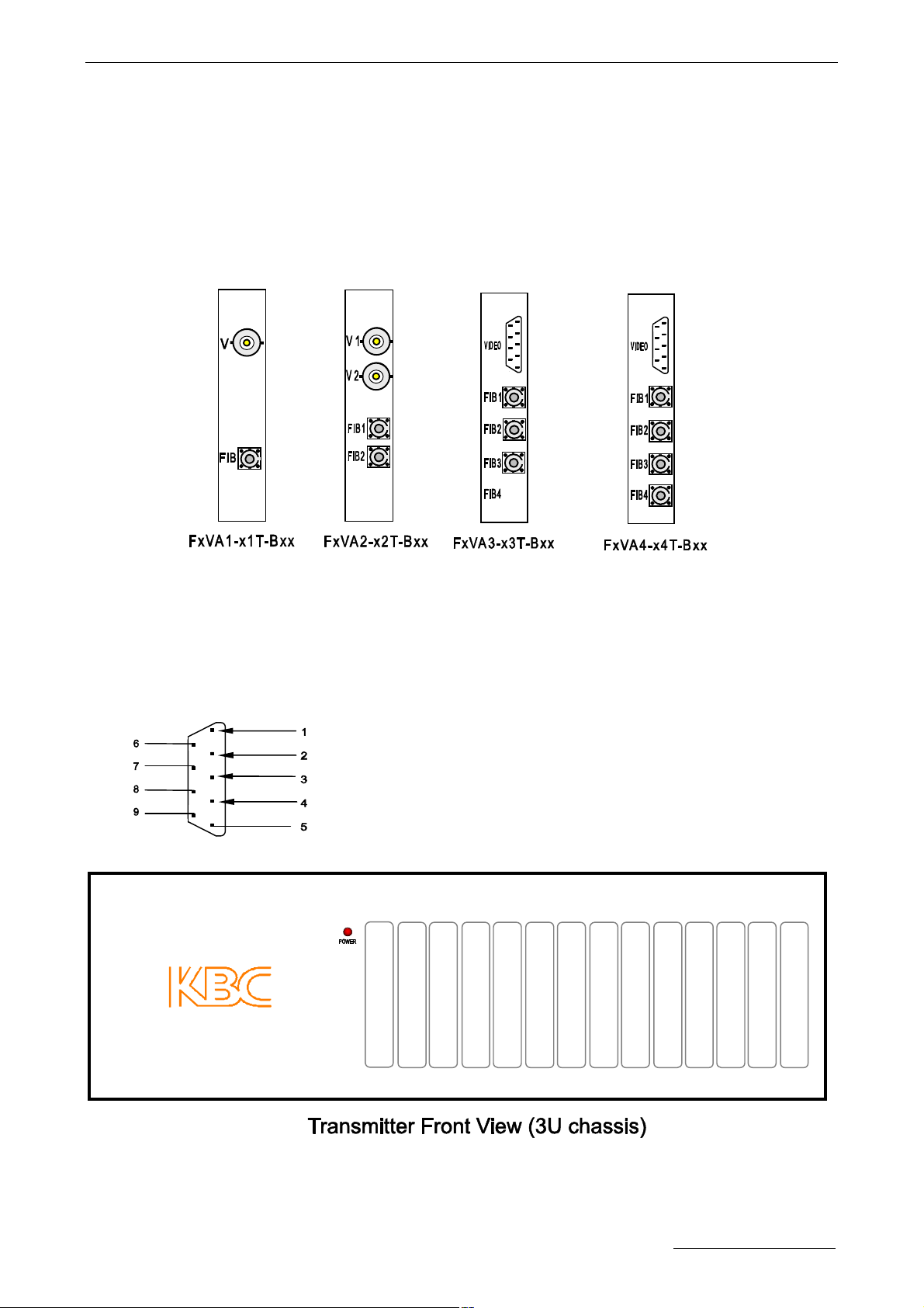
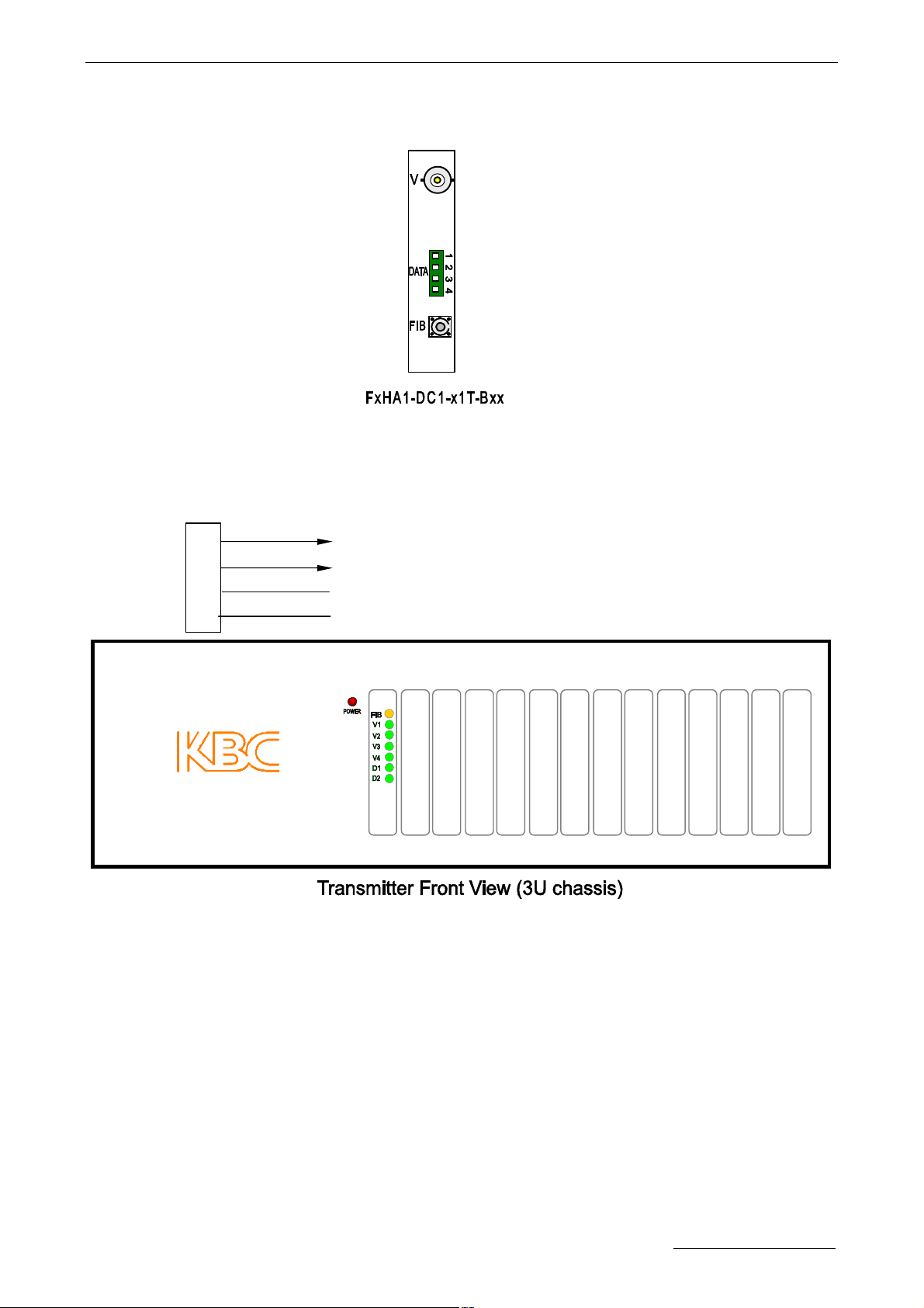
3.1.1 8 Bit Video Transmitter
Connectors:
FIB,FIB1-FIB4: Fiber Optic.
V,V1-V2: Video Input, BNC.
Video: Video Input, DB9. DB9 Pins assignment as below:
VIDEO1 Channel 1 Video, input
VIDEO2 Channel 2 Video, input
VIDEO3 Channel 3 Video, input
VIDEO4 Channel 4 Video, input
GND Common Ground of Channel 1~4 Video
.
LEDs Definition:
POWER: Power Supply. On if power input is OK.
Manual-FD_BSeries-Rev1008.pdf Page 3 of 34 www.kbcnetworks.com
Copyright © KBC Networks Ltd.
Off if no power present.
No other LED labels for Video Transmitter Cards.
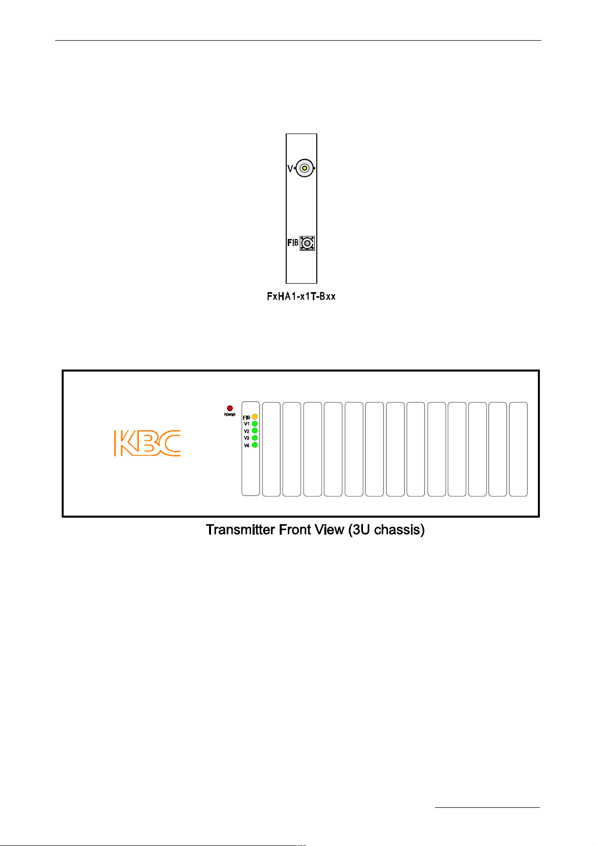
3.1.2 10 Bit Video Transmitter
Connectors:
FIB: Fiber Optic.
V: Video Input, BNC.
.
LEDs Definition:
POWER: Power Supply. On if power input is OK.
Off if no power present.
FIB: Fiber Optic Not used.
V1: ; Video. On if video input is OK.
Off if no video present.
V2-V4: Video. Not used.
3.2 Video Multiplexer Transmitter
Manual-FD_BSeries-Rev1008.pdf Page 4 of 34 www.kbcnetworks.com
Copyright © KBC Networks Ltd.
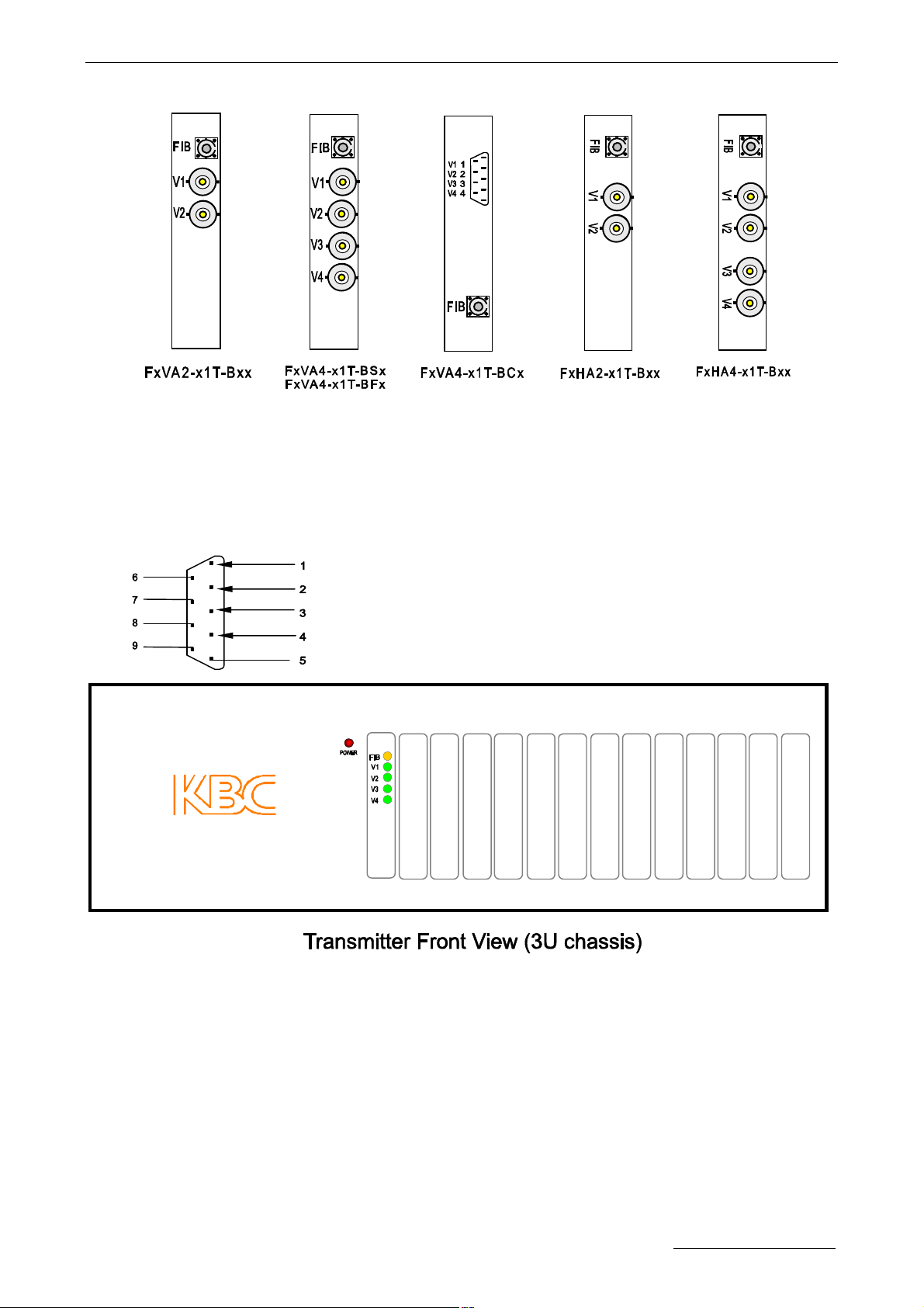
Connectors:
FIB: Fiber Optic.
V1-V4: Video Input, BNC.
V1-V4: Video Input, DB9. DB9 Pins assignment as below:
VIDEO1 Channel 1 Video, Input
VIDEO2 Channel 2 Video, Input
VIDEO3 Channel 3 Video, Input
VIDEO4 Channel 4 Video, Input
GND Common Ground of Channel 1~4 Video
LEDs Definition:
POWER: Power Supply. On if power input is OK.
Off if no power present.
FIB: Fiber Optic. Not used.
V1-V4: ; Video. On if video input is OK.
Off if no video present.
Manual-FD_BSeries-Rev1008.pdf Page 5 of 34 www.kbcnetworks.com
Copyright © KBC Networks Ltd.
3.3 Video Transmitter with return Data
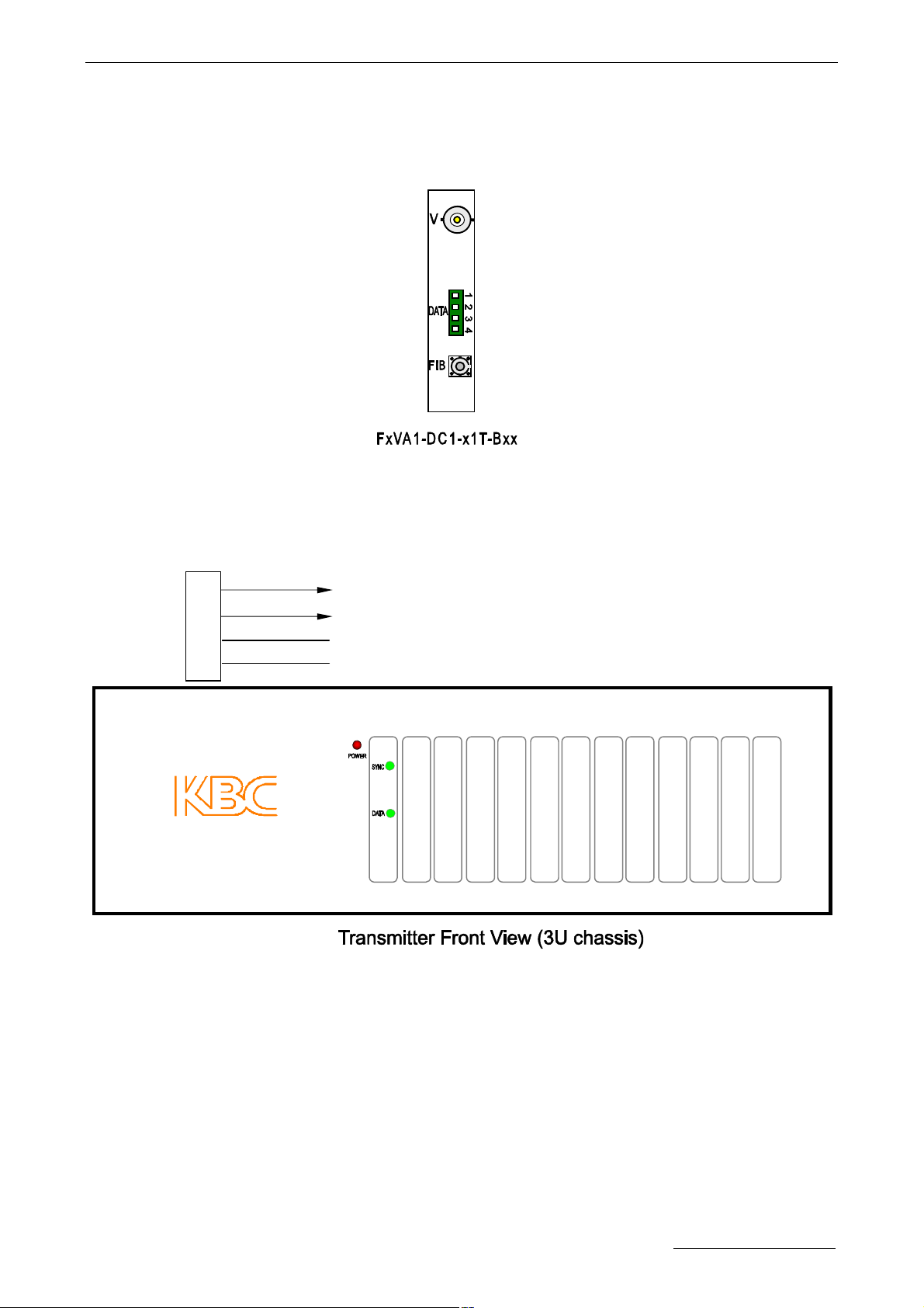
3.3.1 8 Bit Video Transmitter with return Data
Connectors:
FIB: Fiber Optic.
V: Video Input, BNC.
DATA: RS422 Data, Terminal. Terminal pins assignment as below:
RXD+ Data receive signal “+”, output
1
2
RXD− Data receive signal “−”, output
NC
3
4
NC
LEDs Definition:
POWER: Power Supply. On if power input is OK.
Off if no power present.
SYNC: Fiber Link and Video. Flash if the link is not OK.
Off if the link is OK but the video is not OK.
On if the link and the video are OK.
DATA: Data Receive. Flash if data being received.
Off if no data being received.
Manual-FD_BSeries-Rev1008.pdf Page 6 of 34 www.kbcnetworks.com
Copyright © KBC Networks Ltd.
3.3.2 10 Bit Video Transmitter with return Data
Connectors:
FIB: Fiber Optic.
V: Video Input, BNC.
DATA: RS422 Data, Terminal. Terminal pins assignment as below:
RXD+ Data receive signal “+”, output
1
2
RXD− Data receive signal “−”, output
NC
3
4
NC
LEDs Definition:
POWER: Power Supply. On if power input is OK.
Off if no power present.
FIB: Fiber Link. Off if link continuity is good.
On if no link continuity.
V1: ; Video. On if video input is OK.
Off if no video present.
D1: Data Receive. Flash if data being received.
Off if no data being received.
The other LEDs are not used.
Manual-FD_BSeries-Rev1008.pdf Page 7 of 34 www.kbcnetworks.com
Copyright © KBC Networks Ltd.
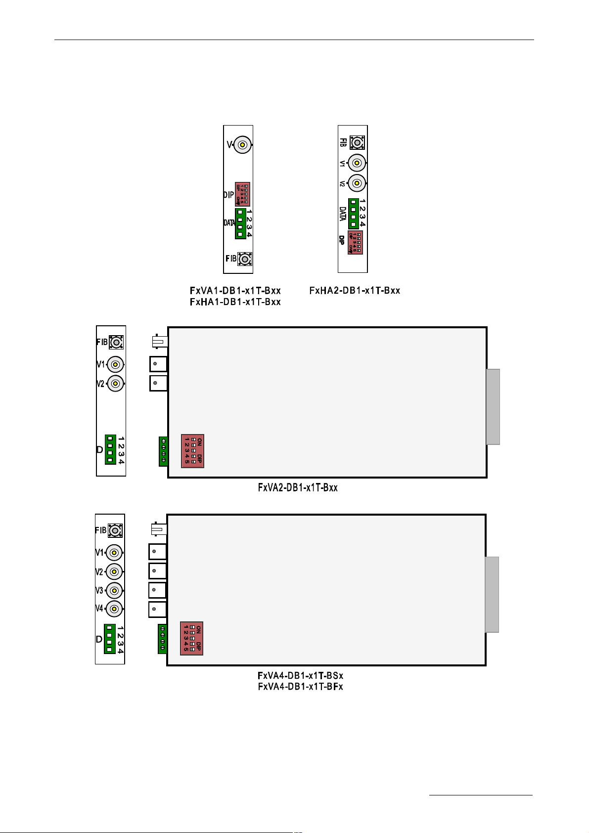
3.4 Video Transmitter with Bi-directional Data
3.4.1 1 Fiber
Manual-FD_BSeries-Rev1008.pdf Page 8 of 34 www.kbcnetworks.com
Copyright © KBC Networks Ltd.

Connectors:
FIB: Fiber Optic.
V,V1-V4: Video Input, BNC or DB9. DB9 pins assignment as below:
VIDEO1 Channel 1 Video, input
VIDEO2 Channel 2 Video, input
VIDEO3 Channel 3 Video, input
VIDEO4 Channel 4 Video, input
GND Common Ground of Channel 1~4 Video
DATA: RS232/RS422/2 wires RS485 or 4 wires RS485 compatible. Terminal pins
assignment and DIP Switch setting refer to Table 1 and Table2 in section 5. Data
Block Connections and DIP Switch Setting.
LEDs Definition:
POWER: Power Supply. On if power input is OK.
Off if no power present.
FIB: Fiber Link. Off if link continuity is good.
On if no link continuity.
V1- V4: ; Channel 1-4 Video. On if video input is OK.
Off if no video present.
D1: RS232/RS422/ 4 wires RS485 Transmit Data, : Flash if data being transmitted.
Off if no data being transmitted.
2 wires RS485 Transmit/ Receive Data, Flash if there is activity.
Manual-FD_BSeries-Rev1008.pdf Page 9 of 34 www.kbcnetworks.com
Copyright © KBC Networks Ltd.

D2: RS232/RS422/ 4 wires RS485 Receive Data, Flash if data being received.
Off if no data being received.
2 wires RS485 Transmit/ Receive Data, Not used.
3.4.2 2 Fibers
Connectors:
FIBa: Channel 1 Fiber Optic.
FIBb: Channel 2 Fiber Optic.
Va: Channel 1 Video input, C3.
Vb: Channel 2 Video input, C3.
Da: Channel1 Data, RS232/RS422/2 wires RS485 or 4 wires RS485 compatible.
Terminal pins assignment and DIP Switch setting refer to Table 1 and Table2
in section 5. Data Block Connections and DIP Switch Setting.
Db: Channel2 Data, RS232/RS422/2 wires RS485 or 4 wires RS485 compatible.
Terminal pins assignment and DIP Switch setting refer to Table 1 and Table2
in section 5. Data Block Connections and DIP Switch Setting.
LEDs Definition:
POWER: Power Supply. On if power input is OK.
Off if no power present.
Manual-FD_BSeries-Rev1008.pdf Page 10 of 34 www.kbcnetworks.com
Copyright © KBC Networks Ltd.

SYNC1: Fiber Link 1 and Video 1. Flash if the link is not OK.
Off if the link is OK but the video is not OK.
On if the link and the video are OK.
SYNC2: Fiber Link 2 and Video 2. Flash if the link is not OK.
Off if the link is OK but the video is not OK.
On if the link and the video are OK.
D1a: Channel1, RS232/RS422/ 4 wires RS485 Transmit Data. :
Flash if data being transmitted.
Off if no data being transmitted.
Channel1, 2 wires RS485 Transmit/ Receive Data.
Flash if there is activity.
D1b: Channel1, RS232/RS422/ 4 wires RS485 Receive Data.
Flash if data being received.
Off if no data being received.
Channel1,2 wires RS485 Transmit/ Receive Data.
Not used.
D2a: Channel2, RS232/RS422/ 4 wires RS485 Transmit Data. :
Flash if data being transmitted.
Off if no data being transmitted.
Channel2, 2 wires RS485 Transmit/ Receive Data.
Flash if there is activity.
D2b: Channel2, RS232/RS422/ 4 wires RS485 Receive Data.
Flash if data being received.
Off if no data being received.
Channel2, 2 wires RS485 Transmit/ Receive Data.
Not used.
3.5 Video Transmitter with Bi-directional Data and Contact Closure
Connectors:
FIB: Fiber Optic.
V: Video input ,BNC.
DATA: RS232/RS422/2 wires RS485 or 4 wires RS485 compatible. Terminal pins
DIP Switch
Manual-FD_BSeries-Rev1008.pdf Page 11 of 34 www.kbcnetworks.com
Copyright © KBC Networks Ltd.

4
assignment and DIP Switch setting refer to Table 1 and Table2 in section 5.
Data Block Connections and DIP Switch Setting.
C1: Contact Closure, input.
C2: Contact Closure, output. The Contact Closure state, Open or Close, of the
contact closure on the transmitter end follows the state of the contact closure
on the receiver end. i.e. if the contact on the receiver end is Close, the contact
on the transmitter end is made to be Close. If the contact on the receiver end is
Open, the contact on the transmitter end is made to be Open.
Terminal pins assignment as below:
Contact Closure input “A”
1
Contact Closure input “B”
2
Contact Closure output “A”
3
Contact Closure output “B”
LEDs Definition:
POWER: Power Supply. On if power input is OK.
Off if no power present.
FIB: Fiber Link. Off if link continuity is good.
On if no link continuity.
V1: ; Video. On if video input is OK.
Off if no video present.
V2-V4: Video. Not used.
D1: RS232/RS422/ 4 wires RS485 Transmit Data. : Flash if data being transmitted.
Off if no data being transmitted.
2 wires RS485 Transmit/ Receive Data. Flash if there is activity.
D2: RS232/RS422/ 4 wires RS485 Receive Data. Flash if data being received.
Off if no data being received.
2 wires RS485 Transmit/ Receive Data. Not used.
Manual-FD_BSeries-Rev1008.pdf Page 12 of 34 www.kbcnetworks.com
Copyright © KBC Networks Ltd.

4
3.6 Video Transmitter with Contact Closure
Connectors:
FIB : Fiber Optic.
V: Video input ,BNC.
C1: Contact Closure ,Input.
C2: Reserved.
Terminal pins assignment:
Contact Closure input “A”
1
Contact Closure input “B”
2
3
NC
NC
LEDs Definition:
POWER: Power Supply. On if power input is OK.
Off if no power present.
FIB: Fiber Link. Not used.
V1: ; Video. On if video input is OK.
Off if no video present.
D1: Contact Closure. On if the contact closure is closed.
Off if the contact closure is open.
The other LEDs are not used.
Manual-FD_BSeries-Rev1008.pdf Page 13 of 34 www.kbcnetworks.com
Copyright © KBC Networks Ltd.

3.7 Bi-directional Data Transmitter
Connectors:
FIB: Fiber Optic.
DATA: RS232/RS422/2 wires RS485 or 4 wires RS485 compatible, Terminal. Terminal
pins assignment and DIP Switch setting refer to Table 1 and Table2 in section 5.
Data Block Connections and DIP Switch Setting.
LEDs Definition:
POWER: Power Supply. On if power input is OK.
Off if no power present.
FIB: Fiber Link. Off if link continuity is good.
On if no link continuity.
V1-V4: Video. Not used.
D1: RS232/RS422/ 4 wires RS485 Transmit Data. : Flash if data being transmitted.
2 wires RS485 Transmit/ Receive Data. Flash if there is activity.
D2: RS232/RS422/ 4 wires RS485 Receive Data. Flash if data being received.
2 wires RS485 Transmit/ Receive Data. Not used.
Manual-FD_BSeries-Rev1008.pdf Page 14 of 34 www.kbcnetworks.com
Copyright © KBC Networks Ltd.
Off if no data being transmitted.
Off if no data being received.

4. Receiver Enclosure
4.1 Video Receiver
4.1.1 8 Bit Video Receiver
Connectors:
FIB,FIB1-FIB4: Fiber Optic.
V,V1-V2: Video Output, BNC.
Video: Video Output, DB9. DB9 Pins assignment as below:
VIDEO1 Channel 1 Video, output
VIDEO2 Channel 2 Video, output
VIDEO3 Channel 3 Video, output
VIDEO4 Channel 4 Video, output
GND Common Ground of Channel 1~4 Video
LEDs Definition:
POWER: Power Supply. On if power input is OK.
Off if no power present.
SYNC1: Fiber Link 1 and Video 1. Flash if the link is not OK.
Off if the link is OK but the video is not OK.
Manual-FD_BSeries-Rev1008.pdf Page 15 of 34 www.kbcnetworks.com
Copyright © KBC Networks Ltd.

On if the link and the video are OK.
SYNC2: Fiber Link 2 and Video 2. Flash if the link is not OK.
Off if the link is OK but the video is not OK.
On if the link and the video are OK.
SYNC3: Fiber Link 3 and Video 3. Flash if the link is not OK.
Off if the link is OK but the video is not OK.
On if the link and the video are OK.
SYNC4: Fiber Link 4 and Video 4. Flash if the link is not OK.
Off if the link is OK but the video is not OK.
On if the link and the video are OK.
4.1.2 10 Bit Video Receiver
Connectors:
FIB: Fiber Optic.
V: Video Output, BNC.
.
LEDs Definition:
POWER: Power Supply. On if power input is OK.
Off if no power present.
FIB: Fiber Link. Off if link continuity is good.
Manual-FD_BSeries-Rev1008.pdf Page 16 of 34 www.kbcnetworks.com
Copyright © KBC Networks Ltd.

On if no link continuity.
V1: ; Video. On if video output is OK.
Off if no video present.
V2-V4: Video. Not used.
4.2 Video Multiplexer Receiver
Connectors:
FIB: Fiber Optic.
V1-V4: Video Output, BNC.
V1-V4: Video Output, DB9 . DB9 Pins assignment as below:
VIDEO1 Channel 1 Video, output
VIDEO2 Channel 2 Video, output
VIDEO3 Channel 3 Video, output
VIDEO4 Channel 4 Video, output
GND Common Ground of Channel 1~4 Video.
LEDs Definition:
POWER: Power Supply. On if power input is OK.
Off if no power present.
FIB: Fiber Link. Off if link continuity is good.
Manual-FD_BSeries-Rev1008.pdf Page 17 of 34 www.kbcnetworks.com
Copyright © KBC Networks Ltd.

On if no link continuity.
V1-V4: ; Video. On if video output is OK.
Off if no video present.
4.3 Video Receiver with return Data
4.3.1 8 Bit Video Receiver with return Data
Connectors:
FIB: Fiber Optic.
V: Video Output, BNC.
DATA: RS422 Data, Terminal. Terminal pins assignment as below:
TXD+ Data transmit signal “+”, input
1
2
TXD− Data transmit signal “−”, input
3
NC
4
NC
LEDs Definition:
POWER: Power Supply. On if power input is OK.
Off if no power present.
SYNC: Fiber Link and Video. Flash if the link is not OK.
Off if the link is OK but the video is not OK.
Manual-FD_BSeries-Rev1008.pdf Page 18 of 34 www.kbcnetworks.com
Copyright © KBC Networks Ltd.

On if the link and the video are OK.
DATA: Data Transmit. Flash if data being transmitted.
Off if no data being transmitted.
4.3.2 10 Bit Video Receiver with return Data
Connectors:
FIB: Fiber Optic.
V: Video Output, BNC.
DATA: RS422 Data, Terminal. Terminal pins assignment as below:
TXD+ Data transmit signal “+”, input
1
2
TXD− Data transmit signal “−”, input
3
NC
4
NC
LEDs Definition:
POWER: Power Supply. On if power input is OK.
Off if no power present.
FIB: Fiber Link. Off if link continuity is good.
On if no link continuity.
Manual-FD_BSeries-Rev1008.pdf Page 19 of 34 www.kbcnetworks.com
Copyright © KBC Networks Ltd.

V1: Video. On if video output is OK.
Off if no video present.
D1: Data Transmit. Flash if data being transmitted.
Off if no data being transmitted.
The other LEDs are not used.
4.4 Video Receiver with Bi-directional Data
4.4.1 1 Fiber
Manual-FD_BSeries-Rev1008.pdf Page 20 of 34 www.kbcnetworks.com
Copyright © KBC Networks Ltd.

Connectors:
FIB: Fiber Optic.
V,V1-V4: Video Output, BNC or DB9. DB9 pins assignment as below.
VIDEO1 Channel 1 Video, output
VIDEO2 Channel 2 Video, output
VIDEO3 Channel 3 Video, output
VIDEO4 Channel 4 Video, output
GND Common Ground of Channel 1~4 Video
DATA: RS232/RS422/2 wires RS485 or 4 wires RS485 compatible, Terminal pins
assignment and DIP Switch setup refer to Table 1 and Table2. in section 5.
Data Interface and DIP Setup.
LEDs Definition:
POWER: Power Supply. On if power input is OK.
Off if no power present.
FIB: Fiber Link. Off if link continuity is good.
On if no link continuity.
V1- V4: ; Channel 1-4 Video. On if video output is OK.
Off if no video present.
D1: RS232/RS422/ 4 wires RS485 Transmit Data, : Flash if data being transmitted.
Manual-FD_BSeries-Rev1008.pdf Page 21 of 34 www.kbcnetworks.com
Copyright © KBC Networks Ltd.

Off if no data being transmitted.
2 wires RS485 Transmit/ Receive Data. Flash if there is activity.
D2: RS232/RS422/ 4 wires RS485 Receive Data. Flash if data being received.
Off if no data being received.
2 wires RS485 Transmit/ Receive Data. Not used.
4.4.2 2 Fibers
Connectors:
FIBa: Channel 1 Fiber Optic.
FIBb: Channel 2 Fiber Optic.
Va: Channel 1 Video output ,C3.
Vb: Channel 2 Video output ,C3.
Da: Channel1 Data, RS232/RS422/2 wires RS485 or 4 wires RS485 compatible.
Terminal pins assignment and DIP Switch setting refer to Table 1 and Table2 in
section 5. Data Block Connections and DIP Switch Setting.
Db: Channel2 Data, RS232/RS422/2 wires RS485 or 4 wires RS485 compatible.
Terminal pins assignment and DIP Switch setting refer to Table 1 and Table2 in
section 5. Data Block Connections and DIP Switch Setting.
LEDs Definition:
POWER: Power Supply. On if power input is OK.
Manual-FD_BSeries-Rev1008.pdf Page 22 of 34 www.kbcnetworks.com
Copyright © KBC Networks Ltd.

Off if no power present.
SYNC1: Fiber Link 1 and Video 1. Flash if the link is not OK.
Off if the link is OK but the video is not OK.
On if the link and the video are OK.
SYNC2: Fiber Link 2 and Video 2. Flash if the link is not OK.
Off if the link is OK but the video is not OK.
On if the link and the video are OK.
D1a: Channel1, RS232/RS422/ 4 wires RS485 Transmit Data. :
Flash if data being transmitted.
Off if no data being transmitted.
Channel1, 2 wires RS485 Transmit/ Receive Data.
Flash if there is activity.
D1b: Channel1, RS232/RS422/ 4 wires RS485 Receive Data.
Flash if data being received.
Off if no data being received.
Channel1,2 wires RS485 Transmit/ Receive Data.
Not used.
D2a: Channel2, RS232/RS422/ 4 wires RS485 Transmit Data. :
Flash if data being transmitted.
Off if no data being transmitted.
Channel2, 2 wires RS485 Transmit/ Receive Data.
Flash if there is activity.
D2b: Channel2, RS232/RS422/ 4 wires RS485 Receive Data.
Flash if data being received.
Off if no data being received.
Channel2, 2 wires RS485 Transmit/ Receive Data.
Not used.
4.5 Video Receiver with Bi-directional Data and Contact Closure
DIP Switch
Connectors:
Manual-FD_BSeries-Rev1008.pdf Page 23 of 34 www.kbcnetworks.com
Copyright © KBC Networks Ltd.

4
FIB: Fiber Optic.
V: Video Output, BNC.
DATA: RS232/RS422/2 wires RS485 or 4 wires RS485 compatible. Terminal pins
assignment and DIP Switch setting refer to Table 1 and Table2 in section 5.
Data Block Connections and DIP Switch Setting.
C1: Contact Closure, input.
C2: Contact Closure, output. The Contact Closure state, Open or Close, of the
contact closure on the receiver end follows the state of the contact closure on
the transmitter end. I.e. if the contact on the transmitter end are Close, the
contact on the receiver end is made to be Close. If the contact on the
transmitter end is Open, the contact on the receiver end is made to be Open.
Terminal pins assignment as below:
Contact Closure input “A”
1
Contact Closure input “B”
2
Contact Closure output “A”
3
Contact Closure output “B”
LEDs Definition:
POWER: Power Supply. On if power input is OK.
Off if no power present.
FIB: Fiber Link. Off if link continuity is good.
On if no link continuity.
V1: ; Video. On if video output is OK.
Off if no video present.
V2-V4: Video. Not used.
D1: RS232/RS422/ 4 wires RS485 Transmit Data. : Flash if data being transmitted.
Off if no data being transmitted.
2 wires RS485 Transmit/ Receive Data. Flash if there is activity.
D2: RS232/RS422/ 4 wires RS485 Receive Data. Flash if data being received.
Off if no data being received.
2 wires RS485 Transmit/ Receive Data. Not used.
Manual-FD_BSeries-Rev1008.pdf Page 24 of 34 www.kbcnetworks.com
Copyright © KBC Networks Ltd.

4
4.6 Video Receiver with Contact Closure
Connectors:
FIB: Fiber Optic.
V: Video Output ,BNC.
C1: Reserved.
C2: Contact Closure output. The Contact Closure state, Open or Close, of
the contact closure on the receiver end follows the state of the contact
closure on the transmitter end. I.e. if the contact on the transmitter end are
Close, the contact on the receiver end is made to be Close. If the contact on
the transmitter end is Open, the contact on the receiver end is made to be
Open.
Terminal pins assignment:
NC
1
NC
2
Contact Closure output “A”
3
Contact Closure output “B”
LEDs Definition:
POWER: Power Supply. On if power input is OK.
Off if no power present.
FIB: Fiber Link. Off if link continuity is good.
On if no link continuity.
Manual-FD_BSeries-Rev1008.pdf Page 25 of 34 www.kbcnetworks.com
Copyright © KBC Networks Ltd.

V1: ; Video. On if video output is OK.
Off if no video present.
D1: Contact Closure. On if the contact closure is closed.
Off if the contact closure is open.
The other LEDs are not used.
4.7 Bi-directional Data Receiver
Connectors:
FIB: Fiber Optic.
DATA: RS232/RS422/2 wires RS485 or 4 wires RS485 compatible, Terminal. Terminal
pins assignment and DIP Switch setting refer to Table 1 and Table2 in section 5.
Data Block Connections and DIP Switch Setting.
LEDs Definition:
POWER: Power Supply. On if power input is OK.
Off if no power present.
FIB: Fiber Link. Off if link continuity is good.
On if no link continuity.
V1-V4: Video. Not used.
D1: RS232/RS422/ 4 wires RS485 Transmit Data. : Flash if data being transmitted.
Manual-FD_BSeries-Rev1008.pdf Page 26 of 34 www.kbcnetworks.com
Copyright © KBC Networks Ltd.

wires RS485 output
Off if no data being transmitted.
2 wires RS485 Transmit/ Receive Data. Flash if there is activity.
D2: RS232/RS422/ 4 wires RS485 Receive Data. Flash if data being received.
Off if no data being received.
2 wires RS485 Transmit/ Receive Data. Not used.
5. Data Block Connection and DIP Switch Setting
Table 1:
Pin Name
Data
RS232
RS422
4 wires
RS485
2 wires
RS485
Data transmit signal;
input
Data transmit signal
“+”, input
Data transmit signal
“+”, input
(not connected)
Table 2:
DIP Switch pin name RS-232
D1( RS422/4 wires RS485 input terminator
120Ω )
D2( 2 wires RS485, RS422 or 4 wires RS485
output terminator 120Ω )
D3( 2 wires RS485 or 4
Pull-up/Pull-down resistance )
D4( RS232/RS422/2 wires RS485 or 4 wires
RS485 select )
D5( RS232/RS422/2 wires RS485 or 4 wires
RS485 select )
1 2 3 4
TXD
Data receive signal;
output
TXD+
Data transmit signal
“−”, input
485 TX+
Data transmit signal
“−”, input
NC
(not connected)
RXD
TXD-
485TX-
NC
GND
GND of RS232 data
RXD+
Data receive signal
“+”, output
485RX+
Data receive signal
“+”, output
485+
Data signal “+”
RS-422
OFF
OFF
OFF OFF
OFF OFF ON ON
ON OFF OFF ON
ON/OFF ② ON/OFF ②
ON/OFF ② ON/OFF ② ON/OFF ②
ON/OFF ① ON/OFF ①
(not connected)
Data receive signal
“−”, output
Data receive signal
“−”, output
Data signal “−”
4wire
RS-485
NC
RXD-
485RX-
485-
2wire
RS-485
OFF
① The 2 wires RS485 OR 4 wires RS485 output bus pull-up and pull-down resistance usually should be
switched on. But if there are several fiber transmitters or receivers, 2 wires RS485 or 4 wires RS485
output interfaces are connected together, only one of the 2 wires RS485 or 4 wires RS485 output
Pull-up and Pull-down resistance should be switched on, the others should be switched off.
② The terminators can be switched on or off according to the RS485 bus connection. When the fiber
transmitter or receiver is placed at the end point of bus, the terminators are usually switched on, but
not be must, so the same as RS422.
Manual-FD_BSeries-Rev1008.pdf Page 27 of 34 www.kbcnetworks.com
Copyright © KBC Networks Ltd.

+ -
12V DC
+ -
Typeical
Application 1
6. Caution
• Switch off all power supply before installation.
• Ensure fiber is properly aligned to the Fiber connector.
• Do NOT stare at the fiber core.
7. Typical Application
Transmitter(3U)
Camera4 Camera1
Camera2
Camera1
12V DC
POWER
FIB1
FIB2
FIB3
FIB4
VIDEO1
VIDEO2
VIDEO3
VIDEO4
Camera3
POWER
FIB1
FIB2
Camera2
Camera1
VIDEO1
VIDEO2
Camera
Recevier(3U)
Manual-FD_BSeries-Rev1008.pdf Page 28 of 34 www.kbcnetworks.com
Copyright © KBC Networks Ltd.
Matrix Switcher

Camera4
Camera1
Camera4
Camera1
Camera1
Camera2
Camera1
Camera4
Transmitter (3U)
Recevier (3U)
Matrix Switcher
Type Application 2
Manual-FD_BSeries-Rev1008.pdf Page 29 of 34 www.kbcnetworks.com
Copyright © KBC Networks Ltd.

+
12V DC
POWER
-
FIB
DATA
VIDEO
Type Application 3
Manual-FD_BSeries-Rev1008.pdf Page 30 of 34 www.kbcnetworks.com
Copyright © KBC Networks Ltd.

Type Application 4
Manual-FD_BSeries-Rev1008.pdf Page 31 of 34 www.kbcnetworks.com
Copyright © KBC Networks Ltd.

Output:+5VDC, 2
6A
Output:+5VDC,
20A
Output:+5VDC,
26A
8. FR3 Series – Chassis Card Cage
PRODUCT DESCRIPTION
The KBC FR3xx series is a standard 19 inch rack
mounted card cage that accommodates 3U chassis card
products. Different models, such as transmitters and
receivers, may be co-located in the same rack. All
modules located within the rack are hot-swappable so
that it is not necessary to power down the rack when
removing or replacing modules. Rear card insertion
provides an attractive appearance to the front panel.
US Power Plug UK Power Plug
Euro Power Plug Australian Power Plug
100-120VAC Input 100-240VAC Input
200-240VAC Input
SPECIFICATONS
Input:100~240VAC, 2.5A, 50/60Hz
Output:+5VDC, 16A
Input:100~120VAC, 3.15A, 50/60Hz
Output:+5VDC, 20A
Input Voltage
Input:100~120VAC, 3.0A, 50/60Hz
Input:200~240VAC, 1.5A, 50/60Hz
Input:200~240VAC, 2.0A, 50/60Hz
Slots 14 one-inch slots accommodating up to 14 single width modules.
Dimensions (L×W×H) 482.8mm×313.6mm×133mm
MTBF > 100,000 Hours
Operation Temperature -40º ~+70ºC, ambient
Storage Temperature -40º ~+75ºC, ambient
Relative Humidity 0~95% (non-condensing)
Manual-FD_BSeries-Rev1008.pdf Page 32 of 34 www.kbcnetworks.com
Copyright © KBC Networks Ltd.

9. Warranty
n Repair
¨ Please contact your local distributors when product is defective. Please apply RA in
advance and prepay shipping cost when returning the defective product to us. We
will pay the cost for sending it back to you.
¨ Please attach a statement clearly describing the problem.
n We will repair defective product under warranty free of charge to our customer.
n 5 years warranty for product only.
n Any unauthorized modification of hardware and software voids the warranty.
n Warranty does not cover mishandling and/or abuse of the product.
Products comply with the following Safety Label for International Fiber Communication
Equipment.
NOTE: This equipment has been tested and found to comply with the limits for a Class A
digital device, pursuant to Part 15 of the FCC Rules. These limits are designed to provide
reasonable protection against harmful interference when the equipment is operated in a
commercial environment. This equipment generates, uses and can radiate radio
frequency energy and, if not installed and used in accordance with the instruction
manual, may cause harmful Interference to radio communications. Operation of this
equipment in a residential area is likely to cause harmful interference in which case the
user will be required to correct the interference at this own expense.
Warning
This is a class A product. In a domestic environment this product may cause radio
interference in which case the user may be required to take adequate measures.
Manual-FD_BSeries-Rev1008.pdf Page 33 of 34 www.kbcnetworks.com
Copyright © KBC Networks Ltd.

10. Instruction of Disassembly
Instruction of Disassembly of KBC Product
(For EU Directive 2002/95/EEC━WEEE)
Tools Required:
1) 5 mm flat tip screwdriver
2) Φ3 cross tip screwdriver
3) Φ5 cross tip screwdriver
4) Size small snip nose pliers
5) 15 mm spanner
Steps for Disassembly:
1) Remove tightening screws of box cover (1 or 4-8 screws in general).
2) Remove lock nut for BNC with spanner.
3) Remove cover plate.
4) Remove tightening screws for printed circuit board (PCB).
5) In case the assembly has more than one PCB then continue removing the remain
tightening screws until none left.
6) Use snip nose pliers to loose the nut of flange and then remove optic cable
connector (jump wire).
7) Snip off power conducting cable and remove power switch /jack/etc..
8) Take out all PCBs.
9) Disassembly of product completed.
Notice:When a product reaches the end of it’s life—return to KBC
Manual-FD_BSeries-Rev1008.pdf Page 34 of 34 www.kbcnetworks.com
Copyright © KBC Networks Ltd.

Version 3.0

Headquarters:
KBC Networks, Ltd.
25691 Atlantic Ocean Drive,
Suite B3
Lake Forest, CA 92630
U.S.A.
Main: 1-949-297-4930
Fax: 1-949-297-4933
KBC Networks Ltd., EMEA
Carlton Suite, Barham Court
Teston, Maidstone
Kent ME18 5BZ
United Kingdom
Office: +44(0)1622618787
Fax: +44(0)2071008147
Email: info@kbcnetworks.com
Web: www.kbcnetworks.com
 Loading...