

Kay Elemetrics 1520A Service manual
Issue
A
1972
OPERA
TIONS
MAINTENANCE
Swept
Frequency
Model
and
MANUAL
Generator
1520A
Toll-Free
KAY
Kay Elemetrics Corp.
2 Bridgewater Lane
Lincoln Park, NJ 07035-1488
Telephone
: 1-800-289-5297 (In
Tel:
(973) 628-6200
Fax: (973) 628-6363
USA
USA
and
Canada
only)
lq SSUE
..A
1972
1520
! .
!
.
i
i.
,
!- .
J:
SWEPT
GENERATOR
FREQUENCY
··;W
/lj/
.
,
;
i
,
I
I
i
,"
i
;
---
t
1520
SWEPT
FREOUENCY
GENERATOR
1-
' -
1 _
J _
PARAGRAPH
1. I I
'.2
1.3
2.1
2.2
2.3
2.4
NTRODUCT
SPECIFICATIONS.
'
INsTALLATION
INTRODUCTION
FUNCTION
FUNCTION
-oPERATIGN
SECTION
ION
. . • . . . . .
.••.••••
OF
CONTROLs
OF
CONNECTORS
.'
•.
,. . '
SECTION
OPERATOR'S
TABLE OF
GENERAL
SECTiON
I I
•...
AND
SWITCHES
•..
•....
1'1
CHECK-OUT
MANUAL
CONTENTS
INFORMATION
. ..
OPERATION
.
•....•
'
.•.
.....
..•••••••.•
-. '
•.••.
~
••........
PROCEDURE
-
.•,.•...
',
•.•..
•
.~'.
. . •
PAGE
• J
• • I
.2
3
3
6
6 _
! ,
J _
j
~
3.
3.2
I
INTRODUCTION
PROCEDURE
..••.•
.......•.....
--
.•••.
'
...•
..
16
16
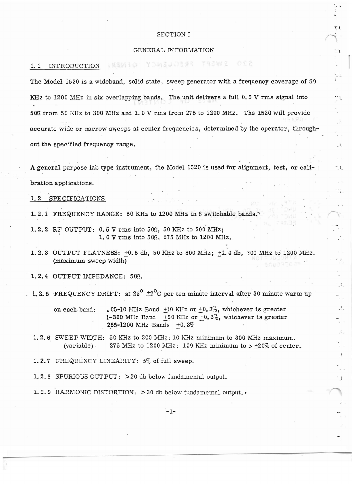
1. 1 INTRODUCTION
The
KHz
500
Model
to
from
1200
50
1520
isawideband,
MHz
in
KHz to
300
stx
overlapping
MHz
SECTION I
GENERAL INFOR11ATION
solid
and
1.0
state,
bands.
V
rms
sweep
The
from
unit
generator
deliversafull
275 to
1200
withafrequency
0.5
V
rms
MHz.
The
1520
coverage
signal
will
provide
of
into
50
"'
,
, '-
accurate
out
the
A
general
bration
1.
2.
1.2.1
1.
2~
2
1.2.3
1.2.4
1.2.
5
wide
or
narrow
specified
purpose
frequency
lab
applications.
SPECIFICATIONS
FREQUENCY
RF
OUTPUT:
OUTPUT
(maximum
OL"TPUT
FREQUENCY
R..L\NGE:
FLATNESS:
sweep
IMPEDANCE:
DRIFT:
sweeps
type
0.5
V
1. 0 V
width)
at
center
range.
instrument,
50 KHz to
rms
into
rms
into
.::0.5
db,
500.
0
at
25
frequencies,determined
the
Model
1200
500,
50
500,
275
50 KHzto800
!2°C
per
1520
:MHzin6
KHz
to 360 lVIHz;
~'1Hz
to
ten
minute
1'lliz;
is
used
switchable
1200
11Hz. ,
,::1.0
interval
by
for
alignment,
bands,>
db,
mer
the
operator,
:00
MHzto1200
30
minute
test,
tbrough-
or
warm
cali-
1Ylliz.
up
, 1_
-.\.
~
. . ! ,
; .
1.2.6
1.
2. 7
1.
2.8
1. 2. 9
on
e
ach
band:.
SWEEP
VlIDTH:
(variable)
FREQUE~CY
05-10 MHz
1-300
2.55-1200
50
, 275
LINEARITY:
SPURIOUS OL'"TPUT:
HARl\10XIC
DISTORTION: =>30 db
Band
MHz
Band
lv1Hz
KHz
to
300
?vIHzto1200
See
:>20
db
.=10
KHz
.=:50
KHz
Bands
:'11Hz;10KHz
of
below
,::0.3%
1IHz
; 10')
full
sweep.
fundamental
below
-1-
or
,:,0.3%,
or
!o.
3%,
minimum
KHz
minimum
output.
fundamental
whichever
whichever
to
300
to » .::20
output
.•
is
MHz
greater
is
greater
maximum,
t
i0
of
.! ,
center.
' J
! ,

1.
2.10
RF
ATTENUATION:
0 to 70
dbin10 db
steps;
0 to 10 db ve
Fnier
,
1. 2. 11
1.
2.12
1.
2.13
1.
2.14
ATTENUATION
SWEEP
RATE:
HORIZONTAL
EXTERNAL
1200
MHz.
front
panel
' t . 2. 15 INTER.:-rAL
1.,2. 16
1.2.17
;BLA~KING:
,
ELECTRICALREQUIRE::\IENT.S:
ACCURACY: +1 db.
0.5
to 6
Hz,
OUTPUT:
l\1ARKER
Input
voltage
INPUT:
- 20
control.
~L\RKERS:
Harmonic
'Variable
Marker
,
Marker
Sw
itchable
,
.untts
variable;6to
5
volts
peak-to-peak
Provision
mv
minimum.
birdies
birdies
Accuracy:
Amplitude:
vertical
..
115
60 ·Hz,
for
at
from1,00
.005%
output
V.!10%,
variable;
sawtoothatthe
two,
at
any
Amplitude
1,
10,
continuously
and
100
KHz to 100
for
Harmonic;
approximately
returned
to
60 Hz., 65
Line
Triggered;
sweep
frequency
repetition
from
variable
MHz.
MHz.
.02%
for
0.1V,peak-to-peak.
zero
reference
'Wapproximately.
100
Var
level.
CWo
rate.
KHz to
via
iable
,
..-.
1. 3 L'N'STALLATION
,
1.
3.1
UNPACKING ,
,'
Upon
occured
receipt
'in
shipment.
connectors,
1. 3. 2
INITIAL
The
urn t
L"'iSTALLATION
may
, '
temperature,
however
amount
of
it
air
should
of
the
Model
and
dial
faces.
be
instnlledinany
humidity,
notbeobstructed.
flow to
prevent
'Pay
or
1520,
visually
particular
environment
vibration.
overheating
inspectitfor
attention
'Adequat e
Rack
mounted
.
-2-
any
damage
to
the
conditionofthe'cabinet,
thatisreasonably
ventilation
models
is
alsorequ
that
free
from
provided
ire
may
extremes
by
the
an
have
sw
itche
cabinet,
adequate
s ,
in
,
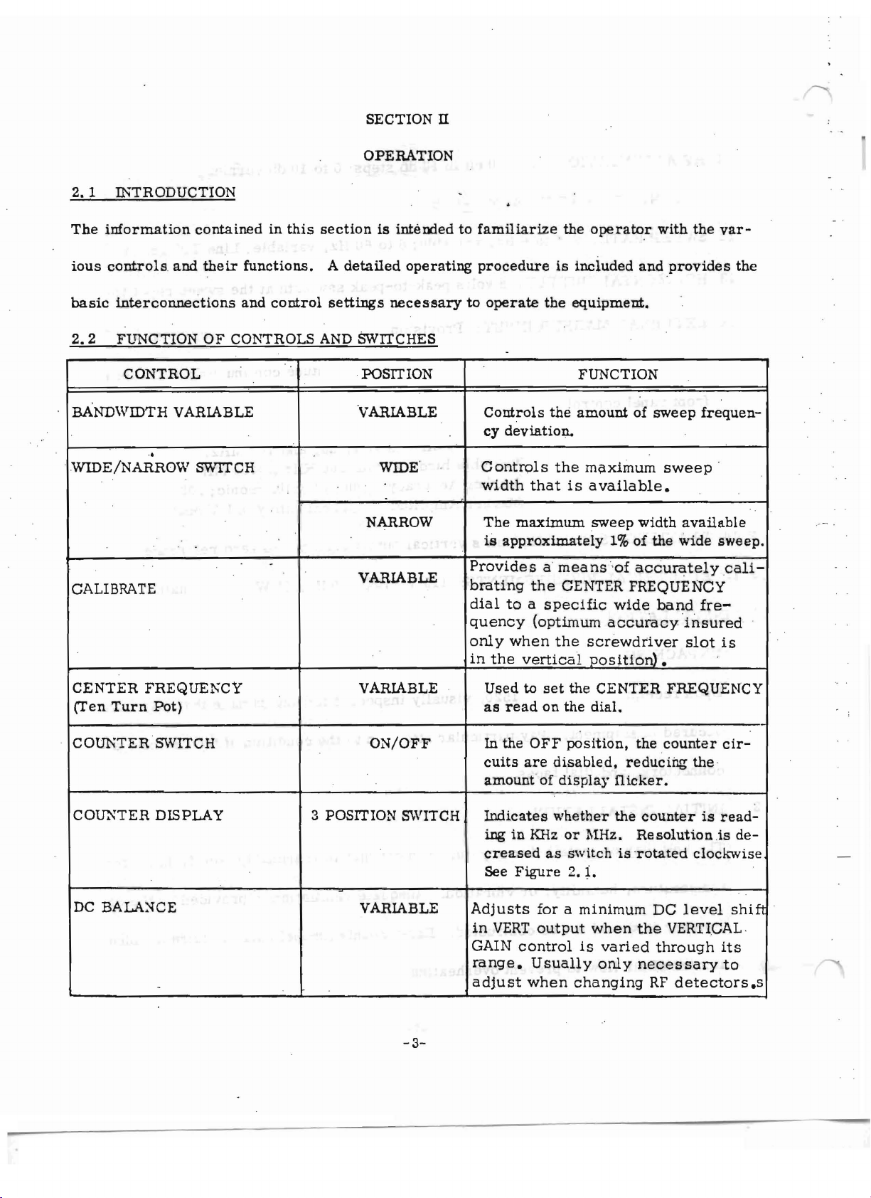
2. 1 INTRODUCTION
The
information
ious
controls
containedinthis
and
their
functions.
SECTION n
OPERATION
sectionisInterdedtofamiliarize
A
detailed
operating
procedure
the
is
included
operator
with
and
the
provides
var
-
the
basic
2.2
interconnections
FUNCTION
OF
CONTROLS AND SWITCHES
CONTROL
BANDWIDTH VARIABLE
.,
WIDE/NARROW
SWITCH
CALIBRATE
CENTER
(T'en
FREQUE};CY
Turn
Pot)
and
control
.
settings
necessary
POSITION
'VARIABLE
WIDE
'
NARROW
VARIABLE
VARIABLE Used to
to
operate
-
Controls
cy
deviation.
Controls
width
The
maximum
is
approximately
Provides
brating
dial
toaspecific
quency
only
when
in
the
as
read
the
equipment.
FUNCTION
the
amountofsweep
the
maximum
that
is
available.
sweep
1%of
a
means
the
CENTER FREQUENCY
'of
accurately
wide
(optimum
the
vertical
set
on
the
accuracy
screwdriver
position).
the
CENTER
dial.
sweep
width
the
available
wide
band
'i nsured
slot
FREQUENCY
frequen-
'
sweep.
cali-
fre-
is
COID-;TER SWITCH
COIDiTER DISPLAY
DC
BALA~CE
-
ON/OFF
3 POSITION SWITCH
VARIABLE
-3-
In the
cuits
amoun
OFF
are
t' of
Indicates
ing
in KHzorMHz.
creased
See
Figure
Adjusts
in
VERT
GAIN
range.
adjust
control
Usually
when
position,
disabled,
display
whether
as
switchis'r otated
reducing
nicker.
the
2. r,
foraminimum
output
when
is
varied
only
changing
the
counter
cir-
the
counterisread-
Resolution.is
clockwise
DC
level
the
VERTIGAL,
through
necessary
RF
derector
shift
its
to
de-
s ss
1.
t
J
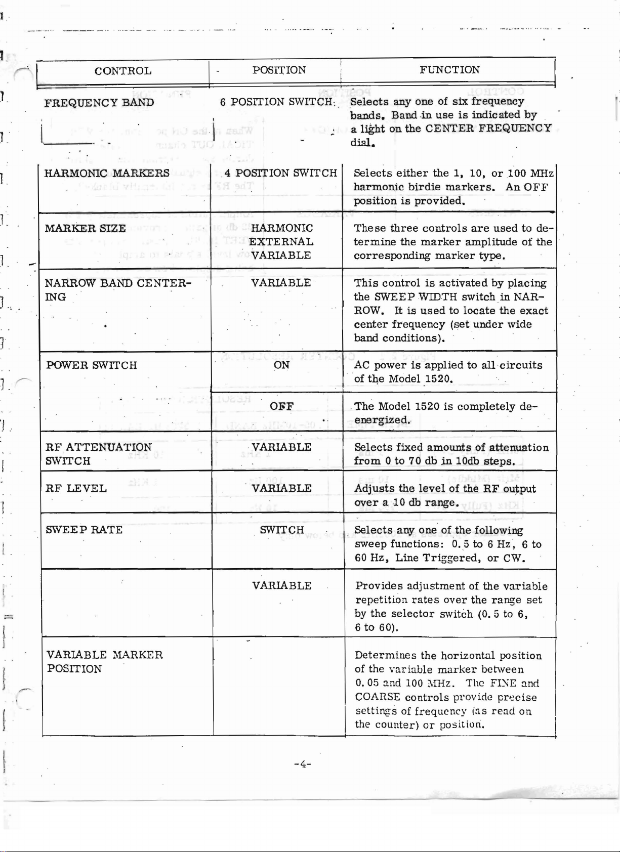
CONTROL
FREQUENCY
BAND
POSITION
6 POSITION SWITCH:
I
!
Selects
bands.
a
dial.
l~t
anyone
Band
on
the
FUNCTION
of
six
frequency
-in
useisindicated
CENTER
by
FREQUENCY
1.
L
1
1.
1.
L
'./
HARMONIC MARKERS
MARKER
SIZE
--
NARROW BAND
ING
..
.
POWER
r":
RF
SWITCH
SWITCH
ATTENUATION
CENTER-
,
_ .. -
.4 POSITION SWITCH
HARMONIC
EXTERNAL
VARIABLE
VARIABLE
ON AC
O~F
..
VARIABLE
Selects
harmonic
positionisprovided.
These
termine
corresponding
This
the
ROW• Itisused
center
band
of
.
The
ene
Selects
from0to
either
three
the
control
SWEE P WIDTH
frequency
conditions).
powerisapplied
the
Model 1520.
Model 1520iscompletely
rgized,
fixed
the
birdie
70 dbin10db
markers.
controls
marker
marker
is
activated
amounts
1,
10,
or
.100 MHz
AnOFF
are
usedtode-
amplitudeofthe
type.
by
placing
switchinNAR-
to
locate
(set
to
the
under
all
circuits
of
attenuation
steps.
wide
exact
de-
I
RF
LEVEL
SWEEP
RATE SWITCH
VARIABLE
VARIABLE
Adjusts
over
.
Selects
sweep
60
Hz,
Provides
repetition
by
the
6to60).
the
alO
db
anyone
functions:
Line
adjustment
rates
selector
levelofthe
range.
of
the
O.
,5 to 6
Triggered,
of
over
switch
RF
output
following
Hz,
or
CWo
the
variable
the
range
(0.5
to 6,
6 to
set
-
VARIABLE MARKER
POSITION
l
J
1
J
-4-
Determines
of
the
0.05
and
COARSE
settings
the
I
counter)
the
horizontal
variable
100 :\IHz. The FI);'E
controls
of
marker
pr
frequency
or
position.
ov ide
ins
position
between
precise
read
and
on
I
.. ..
;:'.
,
-.
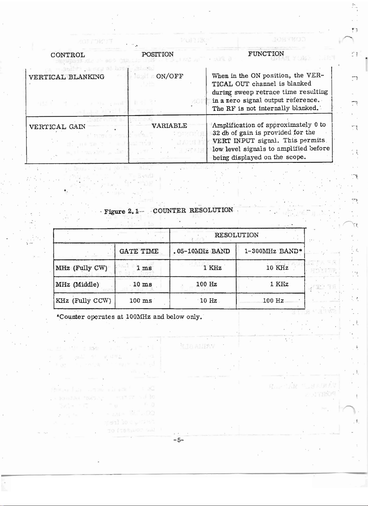
CONTROL
VERTICAL
VERTICAL
BL..-\N~G
CL<\IN
'.
-Figure
POSITION
ON/OFF
VARIABLE
2.1-···.'COUNTER
..
..
RE
SOLU'l'ION.
FUNCTION
When.inthe
TICAL OUT
durtng
in
The
Amplification
32
VERT
low
being
sweep
a
zero
RFisnot
db
of
gainisprovided
L.'iPUT
level
displayed
signal
signals
ON
position,
channel
retrace
output
internally
of
approximately
signal.
to
on
the
the
is
blanked
time
resulting
reference.
blanked
for
This
permits
amplified
scope.
VER-
•.
0 to
the
"before
I
I
I
I
I
..
-.~
'.
:MHz
(Fully
MHz (Middle)
KHz
(Fully
~Counter
operates
CW)
CCW)
GATE
I·
. 10
rooms
at
100~lliz
TIME
Ims
ms
and
RESOLUTION
•
05-10~IHzB.AND
.
1 KHz
100
Hz
10 Hz 100
below
only.
'
1-
.3001'llizBA..'lD* I
10 KHz
1KHz
Hz
I
l.
-5-
-
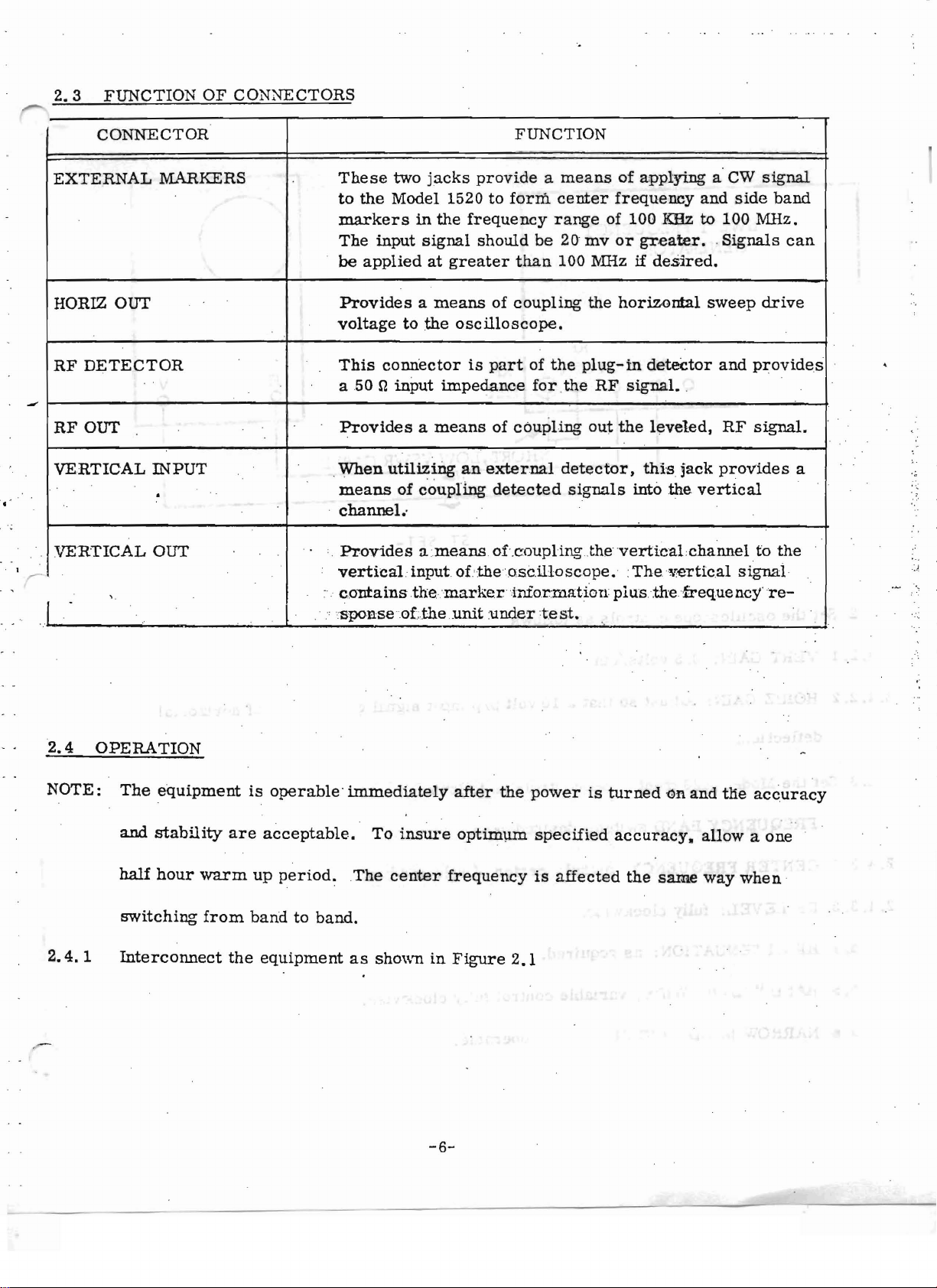
2.3
FUNCTION
CONNECTOR
OF
CONNECTORS
FUNCTION
EXTERNAL
HORIZ OUT
RF
DETECTOR
RFOUT
VERTICAL
VERTICAL
.
"
I
MARKERS
INPUT
.
OUT
These
to
markers
The
be
Providesameans
voltagetothe
This
a50
Providesameansofcoupling
,
When
means
channel
' .
:
Providesameans
verttcal.input
"
contains
.
,·:
sponse o
two
jacks
the
Model 1520 to
in
input
signal
appliedatgreater
connector
n
input
utiliziriganexternal
of
coupling
..
.th
e.m
f.:
the .urutunder
provideameans
the
frequency
should
oscilloscope.
is
impedance
of.theosctll.o
ar kentnrozmattorr
of
partofthe
detected
of.coupling.fhevertfcal
form
center
range
be
20
than
100
coupling
for.the
detector,
:t e
st.
of applying a' CW
frequency
of 100
mv
or
greater.
rvIHzifdesrred.
the
horizontal
plug-in
RF
out
signals
scope.:The
detector
signal.
the
leveled,
this
into
plusthefreque
and
side
KHz
to
100 MHz.
.
Signals
sweep
and
.
RF
jack
provides
the
vertical
.channeltothe
vertical
stgnal
ncy're-
signal
band
can
drive
provides
signal.
a
.~.
.)
2.4
NOTE:
2.4.1
OPERATION
The
equipment
and
stability
half
hour
switching
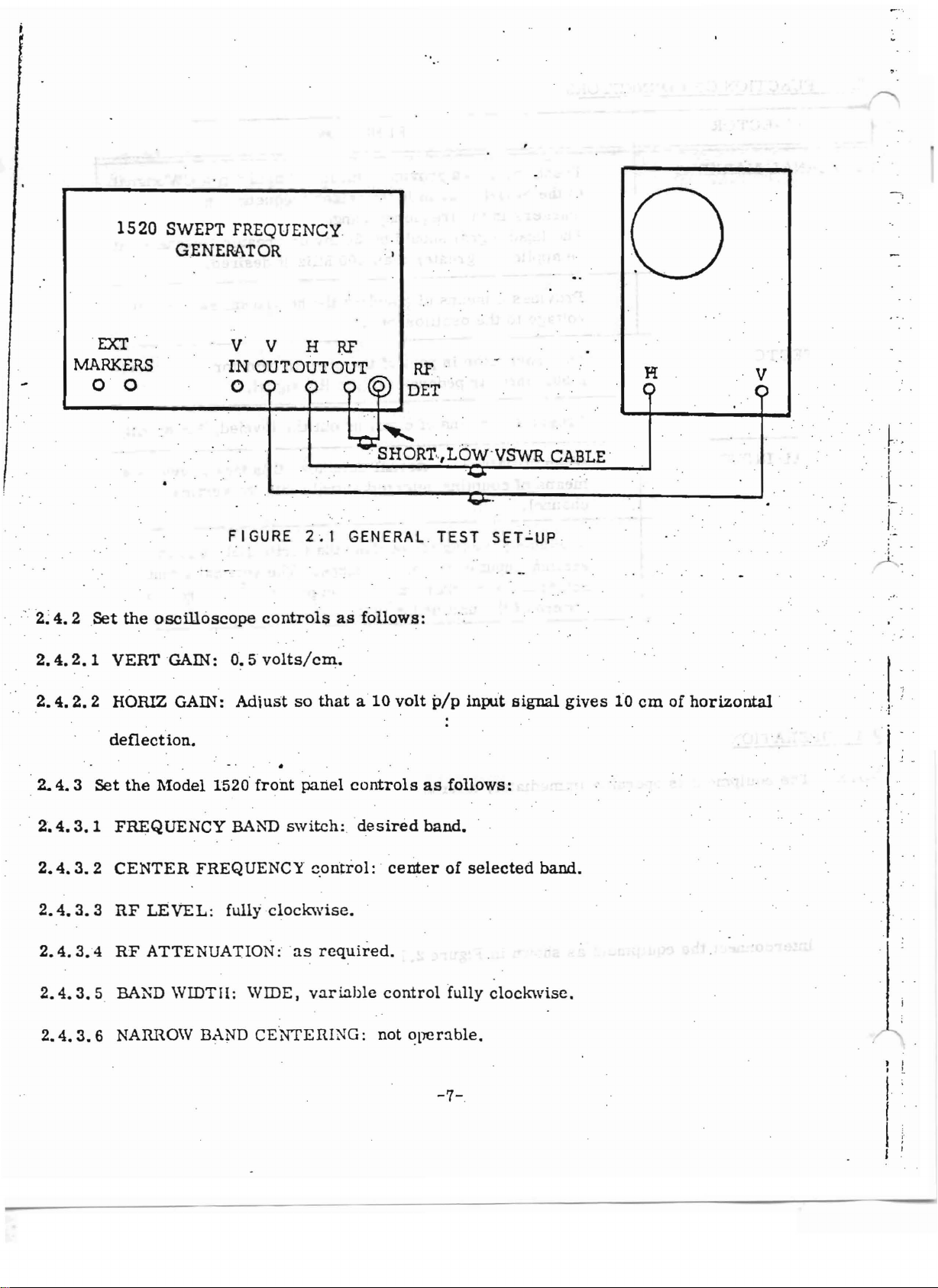
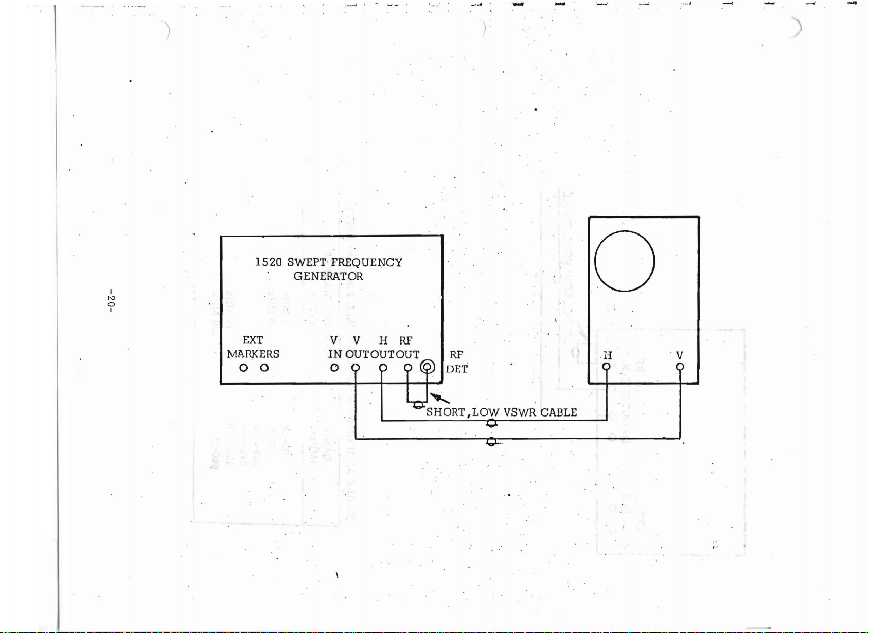
Interconnect
are
warm
from
the
is
operable'immediately
. . . . . . ..
acceptable.
up
period~The
bandtoband.
equipment
To
insure
center
as
showninFigure
after
optimum
frequency
-6-
the
2.1
power
specified
is
affected
is
turned
accuracy.
the
on
same
and
allow
way
the
accuracy
a one
when
'
1520 SWEPT FREQUENCY.
GENERATOR
, I
o
I
'2~
4. 2
2.4.2.1
2.4.2.2
2..
EXT
MARKERS
o 0
Set
,
4. 3
Set
the
oscilloscope
VERT
HORIZ GAIN:
deflection.
the
GAlli:
Model
v V
IN
OUT OUT OUT
00
FIGURE
controls
0.5
'volts/cm.
Adiust
, .
1520'
front
HI:U'
~
2~1
so
panel
0
-~?)
DET
'-..
"SHORT." LOW·V
GENERAL,TEST
as
follows:
that
a 10
volt
controls
RF
pip inpUt
as
follows:
....
.
SET~UP
SwR
signal
CABLE'
gives
H
o
10
emofhorizontal
V
,'J
. t-
~
.
,I',
, '
..
J'
, 'I
2.4.3.1
2.4.3.2
2.4.3.3
2.4.3
2.4.3.5.
2.4.3.6
FREQUENCY
CENTER
RF
LEVEL:
..4
RP
ATTENUATION: 'as
BAND WIDTH: WIDE,
NARROW BAND CE'NTEfiING: not
BAl\'D
FREQUENCY
fullyclockwtse.
switch
control:'center
required.
variable
;
desired
control
operable.
band.
of
fully
-7-
' ,
selected
clockwise.
,
band.

1
2.4.3.7
J
1
1
2.4.3.8
2.4.
2.4.3.10
2.4~3. 11
2.4.3
2.4.3.13
2.4.4
SWEEP
VERTICAL
3. 9 DC
VERTICAL
COUNTER
. 12 HARMONIC
l\1ARKER
With
center
shouldbe
RATE:
BALANCE:
the
controls
as
indicated
observed
6to60
GAIN:
set
BLANKING: ON.
O~/OFF:
1'YIARKER:
SIZE:
set
on
if
Hz
mid-range.
at
factory
OFF.
All
three
as
above,
the
CENTER
the
VERTICAL
position,
OFF.
contrcl
variable
to
match
sfully
the
indicated
FREQUENCY
GAIN
RF
detector;
CCW.
frequency
control
fully
dial.
clockwise.
or
band
· A
is
properly
mid-range.
will
be
frequency
adjusted.
swept
response
with
the
curve
J
2.4.5
The
desired
frequency
band
is
selected
asfollows:
J.
! -
.2.4.5.1
rr>
. .
2.4.
5.2A1low
.2. 4. 5. 3
2.4.6CENTER
2.4.6.
2.4.6.2
2.4.6.3
2.4.6.3.1.Determine
1
.
Place
The
The
Below
marker
The
band
the
FREQUENCY
the
unittostabilize.
selected
FREQUENCY
frequency
roo
MHz,
to
indicate
cal
.ibrat
operation
NALorharmonic
band
will
may
be
higher
the
ionofthe
is
as
the
dynamic
BAND
be
Indicated
selection:
read
center
center
CENTER
follows:
center
marker
selector
.
directly
frequency
frequency.
FREQUENCY
frequency
on
the
in
the
byalight
from
scope
the
accuracy
trace
d~~ired
in
the
dial.
dial
of
the
while
range.
CENTER
is
obtained
fo~
greater
swept
reducing
RE: by
.'
FREQUENCY
by
using
accuracy
cen~ering
the
the
or
an
bandwidth
dial.
variable
na
IT
0\.,"
EXTER-
(use
2.4.6.3
.2
the
VARIABLE BANDWIDTH
Adjust
the
bandwidth
control)
controls[0r rna;..xirnurn
to a
-8-
minimum.
bandwidth.
2. 4.
6~3.
3
Adjust
at
the
at
any
the
horizontal
center
of
bandwidth.
the
)
controls
display.
of
(The
the
oscilloscope
~cope
is
now
so
'astoplace
calibrated
to
read
the
marker
center
exactly
frequency
,.'
~
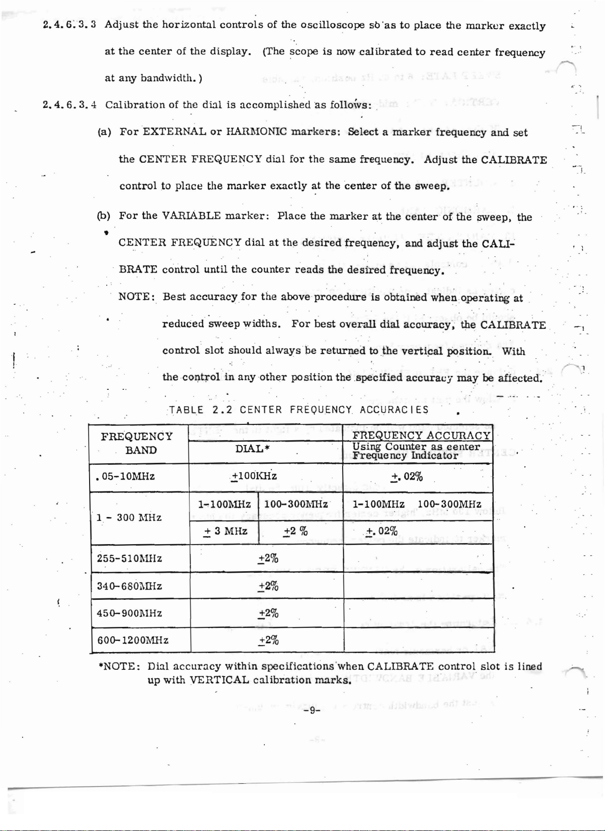
2.4.6.3.4
, .
Calibration
(a)
For
the
control
(b)
For
•
CENTER
, BRATE
NOTE:
of
the
dialisuccompl
'EXTERNAL
CENTER
to
place
the
VARIABLE
FREQUENCY
control
Best
. .. . . . .
reduced
control
the
,co
or
HARMONIC
FREQUENCY
the
marker
marker:
dialatthe
until
the
accuracyfor
sweep
slot
I).
tr ol in
widths.
shouid
.
~
any
counter
dial
exactly
Place
the
always
other
ished
markers:
for
desired
reads
above
For
be
position
'as foflows; ,
Selectamarker
the
at
the
same
the
marker
frequency.
center
frequency.
the
desired
procedure
best
overall
returned
the
.specified
of
at
the
frequency.
is
obtained
dial
to
jhe
Adjust
the
sweep.
center
and
accuracy,
vertical
accuracy
frequency
-of
adjust
' ,
whenoperattng
posttton,
and
the
CALIBRATE ,
the
sweep.
the
CALI
the
CALIBRATE ,
may
be
set
the
.,
at
"
' With
affected,
,-
. - .
-I
' 1
. : .
~
FRE
'QUENCY
BAND
.05-10r.,,1Hz
"
1-
300
:MHz
255-510MHz
34o-680l\lliz
45O-900MHz
60o-1200l\1Hz
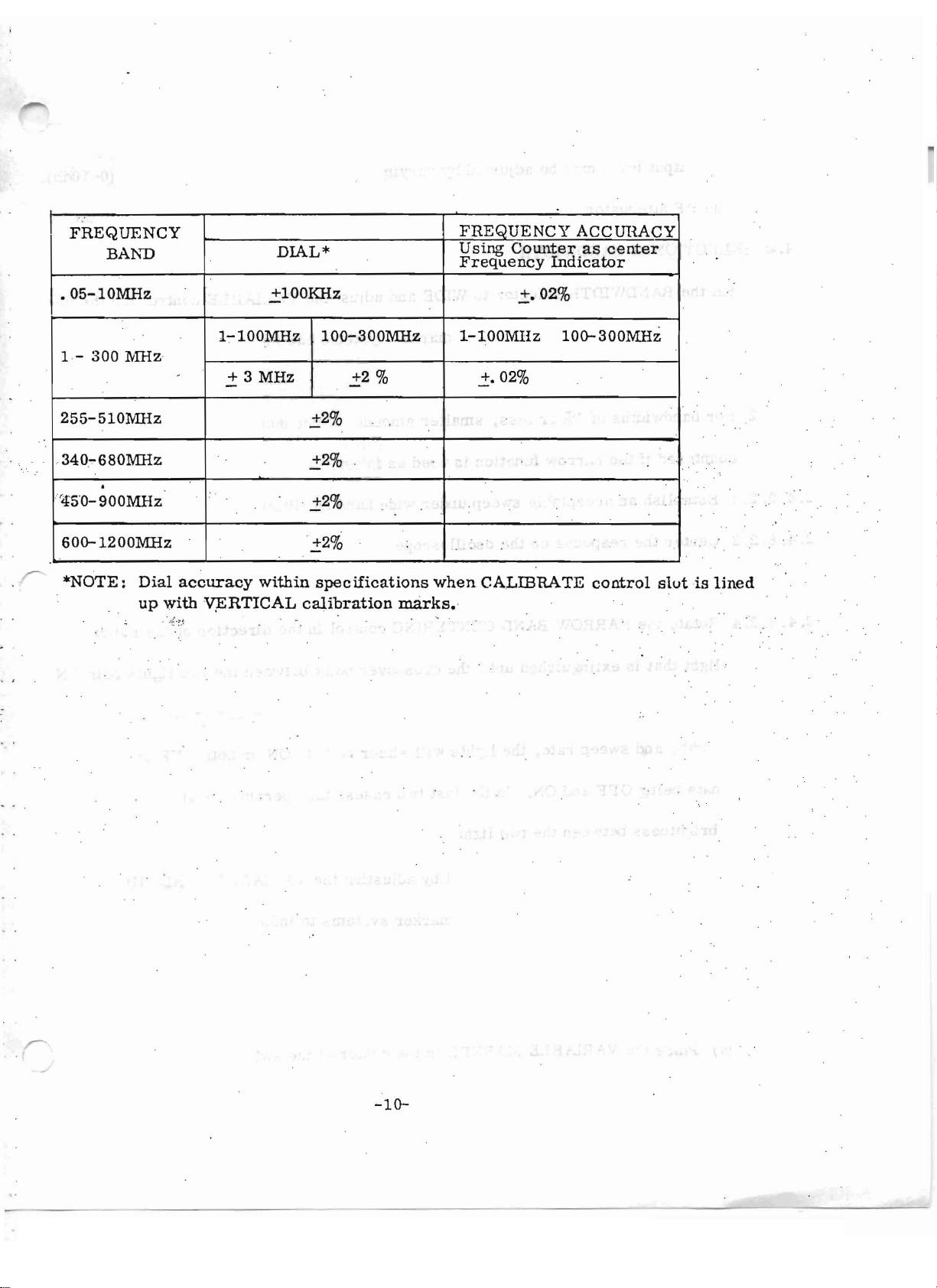
·NOTE:
Dial
up
TABLE
accuracy
with
2.2
CENTER
DIAL*
'-iooxne
-
l..,lOO~1Hz
+ 3
MHz
within
VERTICAL
FR~OUENCY
1
00-
300~n-lz
..:!:2
..:!:2%
01
+2
_ 10
..:!:2%
..:!:2%
spec
iftcat
calibration
%
ionawhen
marks,
ACCURACIES
FREQUENCY
Using
Frequency
'
l-lOOMHz
i·
CALIBRATE
Counter
.:t.
02
%
,
ACCURACY
as
Indicator
02
%
10Q-300MHz
control
center
'
slot
is
lined
-9-
--
FREQUENCY
BA~"'D
DIAL
FREQUENCY
*
Using
Frequency
Counter
ACCmMCY
as
Indicator
center
.OS-10MHz
1-
255-S10l\tIHz
--
340..,.
'4S"O-900MHz
60o-1200:MHz
/"""'
*NOTE:
300
l\Urz
680MHz
.
Dial
up
-
accuracy
with
v;ERTICAL
+100KHz
1-100MHz
+ 3
MHz
-
within
100-300lVIHz
.:!:2
%
.:!:2%
2
.:t
%
.:!:2%
2
2:
%
specifications
calibration
when
marks,
.:t.
l-lOOMHz
.:!:.02%
CALffiRA
02
%
10o-300MHz
TE
control
slutislined
-10-
2.4.7
SWEPI'
RF
LEVEL
adjustment:
2.4.7.1.The
2.4.
8 SE
LECTION
2.4.
8. 1
Set
.
sired
width.
2.4.8.2
J!'or
cqunter
..
2.4.8.2.
2.4.
2.4~8. 2. 3
1
8.2.2
output
the
bandwidths
E~ablish
Center
Select
level
-of BANDWIDTH:
BANDWIDTH
width.
Anyone
of 1%orless,
edifthe
the
the
narrow
an
acceptable
response
NARROW
may
be
adjusted
selector
of
to WIDE
the
-threemarker
smaller
functionisused
sweep
on
the
oscilloscope.
sweep
function.
by
varying
under
the
RF
level
and
adjust
systems
the
VARIABLE
can
be
amountsofresidual
as
follows:
wide
band
conditions.
through
used
FM
its
control
to
establish
and
range
drift
(O-lOdb).
for
the
an
will
de-
exact
be e n-'
--
I
2.4.8.2.4
..
2.4.8.2.5
2.4.8.3
2.4.8.3.1
Rotate
light
..isreached.
width,
nate
brightness
The
trol
the
NARROW
thatisextingurshed
At
and
sweep
being
OFF
between
desired
while
bandwidth
using
. " .
Establishanarrow
For
frequencies
(a)
Place
the
VARIABLE
BANDCENTERING~ontrol
until
the
.crossover
the
crossover
rate,
and
ON.
the
may
anyofthe
bandwidth
from
50 KHz to 100 11Hz,
the
two
:MARKER
In
three
point,
lights
the
lights
be
set
will
last
•
by
marker
and
either
two
adjusting
sweepata known
in
the
dependingonthe
cases,
systems
center
in
point
be
both
the
the
center
proceed
of
the
between
VARIABLE
to
the
direction
the
center
ONorboth
operator
indicate
frequency.
as
follows
swept
of
the
two
lights
frequency,
OFF
should
the
tune
BANPWIDTH
frequency.
:
display.
indicator
bein
or
will
for
ON
band-
alter-
equal
con-
.
(b)
Turn
the
VARIABLE
BA~D\VIDTH
control
-11-
fully
counterclockwise
. .
(c)
Adjust
cy
(d)
OPrIONAL
the
reading
NARROW
on
the
counter.
METHOD:
SWEEP
Adjust
CENTERING
(See
section
the
center
control
for
on VARIABLE
frequency
control
the
desired
MARKER
for
center
operation.
the
crossover
frequen-
)
I ,
f
2.4.8.3.2
2.4.9
2.4.9.1
pointofthe
dial
may
provide
(e)
Adjust
,ofanyofthe
For
frequencies
(a)
Set
. . . ' , . . . . '
SWEEP
The
est
the
with
RATE
variable
rate
that
step's
indicator
now
be
the
same
the
VARIABLE BANDWIDTH
three
above
CENTER
~2.4.8~
ADJUSTMENT
ranges
produces
lights
used
for
noting
center
frequency
marker
100
MHz
FREQUENCY
2.4
and
2.4.
,
(0.5to6 Hz
the
least,distortton
(see
section
the
initial
for
wide
control
typesisuseful
proceed
dial
for
as
any de
8. 2. 5.
and
6 to 60 Hz)
of
2.4.8.2.4).
center
sweeps.
for
the
for
insuring
follows:
sired
are
normally
the
r-esponse
The
frequency
desired
accuracy
center
curve.
CENTER
andisalso
bandwidth.
..
frequency
selected
The
FREQUENCY
arid
for
faster
set
The
proceed
the
rates
up
use
.fa at-
to
I ,
I ,
2.4.9.2
will
produce
. . . .
depends
circuits
When
may
,
bobble,
operating
become
(a) Switch to NARROW BANDWIDTH
(b)
If
the
line
the
least
flicker.
on
the
response
will
ringifswept
at
very
noticeable
proceed
. , ,
as
timeofthe
narrow
asaback
follows:
too
fast.
At
any
given
unit
bandwidths,
and
forth
(setupas
bobbleisstill
frequency
objectionable,
related
F~l
will
switchtothe
disappear.
sweep
under
residual
bobble of
rate',the
test
and
the
FM
picked
the
signal;
for
section
2.4.8.2.4).
LINE TRIGGERED
amountofdistortion
detector;
, .
up:by
:
To
-12-
some
the
reduce
range.
high
system
this
All
Q
,
F'M
2.4.
10 DC BALANCE
2•.
4.10.1
Turn
NOTE:
the
With
the
COUNTER
remain
The
to
COUNTER
counting.
If
the
LlliE
able
to
operate
distortion.
. .
ADJUSTMENT
three
MARKER SIZE
the
rightofthe
switch
TRIGGERED
in
oneofthe
ON/OFF
variable
should,
function
controls
switchinthe
~arker
therefore
should
variable
fully
ranges
counterclockwise.·
ON
(no
be
OFF
produce
which
position,
counting
except
distortion,
produces
residual
error
when
itisadvis-
the
FM.
will
be
actually
minimum
will
noted).
j
I
2.4.10.2
2.4.10.3
2.4.10.4
2.4.10.5
2.4.10.6
2.4.11
2.4.
11.1Set
Disconnect
tween
to
Set
level
vary
does
the
the
VERTICAL
the
on
the
not
Eliminate
Repeat
VERTICAL
the
the
RF
signal
detector
and
lliFUT
oscilloscope's
the
trace.
VERTICAL
deflect
any
this
GAI~
osc
vertically.
deflectionofthe
procedure
ADJUSTIvIENT
illoscope'svertical
from
the
jack)
vertical
GAlli
any
the
Model
..
gain
control
trace
time
gain
detector
1520
to .10
through
the
detector
forO.5 V/
(detector
mv/div
by
adjusting
while
its
is
em.
maintaining
plugged
and
entire
the
changed.
theconnection
into
the
1520orconnected
center
range
the
and
zero
see
DC BALANCE
input.refe
that
the
control.
be.,.
reuce
trace
2.4.11.2
2.4.11.3
Adjust
the
signalsmay
Adjust
the
VERTICAL
GA~
makeitnecessary
l\IARKER SIZE
control
to
controls
foraconvenient
increase
as
the
necessary.
-13-
vertical
amplitude.
sensitivity
Very
of
the
low
level
scope.
2.4.
12
VERTICAL
BLANKING:
.2.4.12.1
2.4.
12.2With
2.4.13
NOTE:
VARIABLE MARKER OPERATION
The
or
widthatwhich
A 2%
the
2.4.13~
..
-:-
..
...
1
To
establishano-signal
the
ON
position.
the
VERTICAL
reverse
accuracy
. , . ' .
less
sweeps
of
marker
·of
.. . . - . -
This
are
the
variable
frequency.
+. 02%.can be
bandwidthismore
variable
Set
the
obtained
marker
COUNTER
is
indicated
accuracy
DISPLAY sw
reference
blanks
BLANKING
displayed
marker
(An.
discerned
useable).
is
.by
the
decimal
line
the
signalatthe
switchinthe
on
the
scope.
(.05
- 100
is.i.
8%
bandWidthisapproximately'
oil
At
bandwidths
place
aID
. -
02%
the
VERTICAL
OFF
MRz)
for
SW8I?t
ern
scope
above
.i0.25% of bandwidth.
itchtothe
desired
: . .
pointonthe
display
VER'.I'ICAL BLANKING
OUT
jacktozero.
position,
frequency
display;
8%
counter
both
+.25
of
the
marker
resolution,
or
may
the
forward
bandwidths
the
max~mum
mm
Resolution
be
determined
switch
and
of
8%
band-
or
.oi«.
frequency,
in
NOTE:
I ,
2.4.13.2
2.4.13,;3Adjust
2.4.13.4·Adjust
..;.4. 13. 5
from
Setting
the
chart
a
resolution
in
mended..Reduced
.
frequencyresolution.
Turn
the
COUNTER
counter.
sired
Read
The
marker
the
VARIABLE MARKER POSITION
point
or
frequency.
the
~1ARKER
the
marker
the
section
greater
flicker
than
when
ON/OFF
being
countedisindicated
SIZE - VARIABLE
frequency
directly
concerning
the
specified
the
functionofcontrols
accuracy
-countingisinsured
switch
to ON
and
controls
control
from
the couruer ,
-14-
of
the
reading
by
workingatthe
read
the
frequency
by a
bright
to
place
dotatthe"
the
foraconvenient
.and
switches.
is
minimum
directly
marker
marker
notreccm-
useful
fr0Il?-
peak.
at
its
de-
amplitude
the
.
2.4.
13.
2.4.13.7
6
If
counting
e
ssary
When
the
to
the
counter
produces
count
.
SWEEP
frequency
objectionable
the
frequency
RATE,
.
BANDWIDTH,
may
vary
flicker,
slightly.
turn
or
COUNTER
This
the
counter
variation
OFF
DISPLAY
will
be
whenitis
controls
within
specifica-
are
not
varied,
nec-
. : ', . , ',
tions.
within
2.4.
14 HARMONIC :MARKER
2.4.14.1
Select
of
2.4.
14.2Vary·
ed.
2.14.15
NOTE:
EXTERNAL
External
are
2
~
14.
15.1
To
Counter
its
'anyone of
the
HARMONIC MARKER .swttch•
the
markers
only
specified
generateacenter
variation
specified
MARKER
MARKER
may
from
is
limits.
OPERATION
the
harmonic
SIZE
- HARMONIC
OPERATION:
be
generated
100
·frequency
minimized
marker
KHz
to
at
any
100
:MHz.
marker,
by
setting
frequencies
control
until
pointinthe
connect
the
resolution
(1,
10,·and
the
frequency
an
external
desired
of
the
counter
100 MHz).by
amplitude
range
slgnal
although.
generator
means
is
obtain-
they
to
2.14.
15.2
2.14.15.3
2.14.15.4
2.14.15.5
2.14.15.6
the
EXTERNAL
Select
some
Adjust
To
of
into
A
the
value
the
minimize
the
MARKER SIZE
the
sideband
input at
The
marker
generators.
desired
less
MARKER
harmonics,
scope
marker
the
proper
level
:MARKER
frequency
than
0.5
SIZ~
control
display.
canbegenerated
frequency.
may
be ad
input
jack.
from
this
v
rms,
-EXTERNAL
keep
the
RF
as
highaspossible
justed
by
-15-
signal
generator
control
input
level
by
feedingasignal
regul
ating
and
. .
forauseable
as
lowaspossible
without
introducing
into the
the
relative
adjust
marker
signal
itsRF
. .
.arid
the
excess
remaining
level
level
marker
~f
the
for
setting
noise
two
,
-
1
1
,
1.
1.
J,
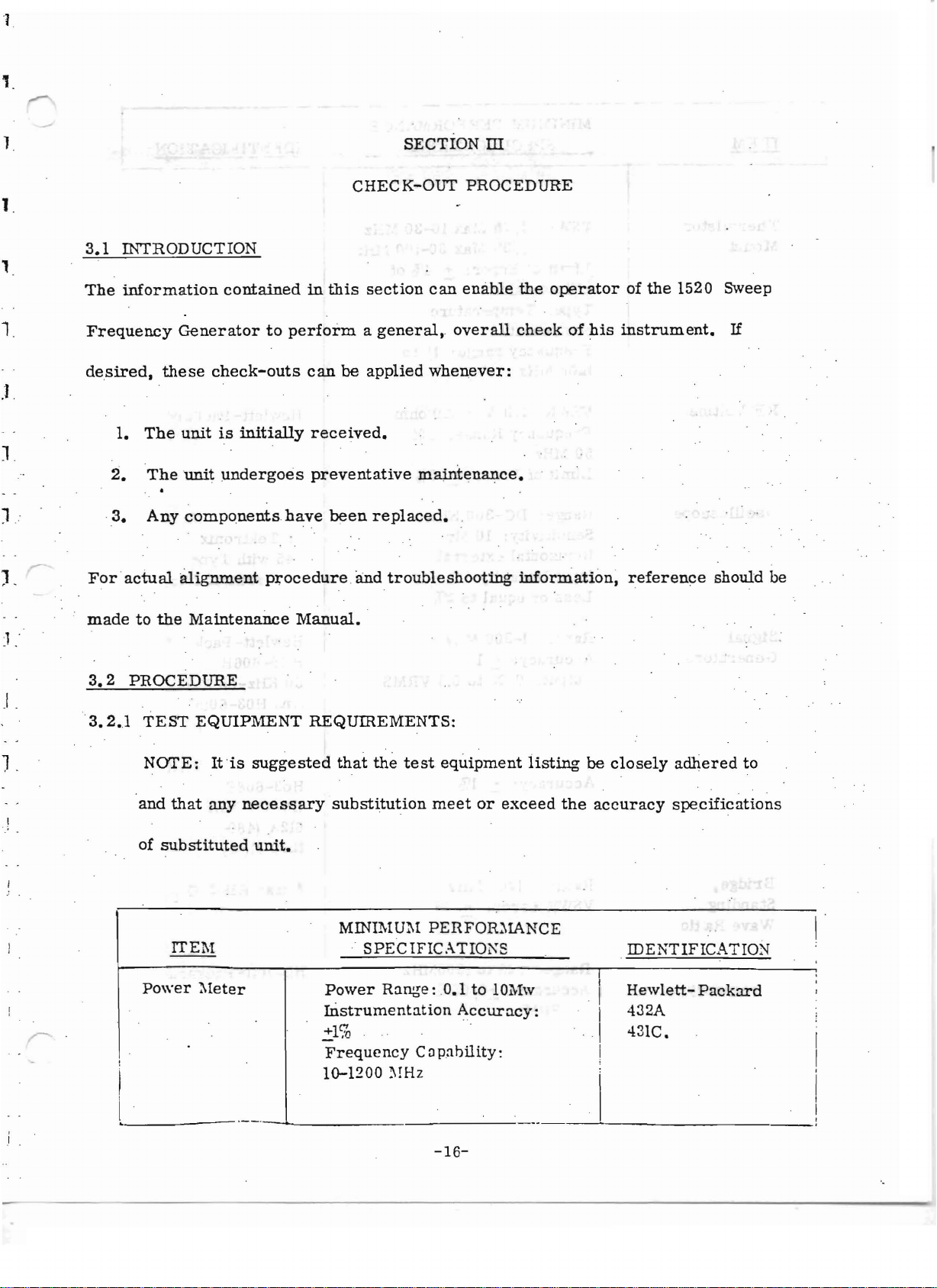
3.1
INTRODUCTION
The
information
Frequency
desired,
1.
2.
·3.
For
these
The
The
Any
actual
contained
Generator
check-outs
unitisinitially
unit
components
al.ignment
to
undergoes
procedure
SECTION
CHECK-OUT
in
this
section
performageneral,
can
be
applied
received.
preventative
have
been
replaced.
and
troubleshooting
ill
PROCEDURE
can
enable
overall
whenever:
maintenance.
the
operator
checkofhis
informatton,
of
the
1520 Sweep
instrument.
reference
If
should
be
J,"
).
made
3.2
PROCEDURE
-3.2.1
,
,
to
the
TEST
NOTE:
and
that
of
substituted
ITEM
Power
Maintenance
EQUIPMENT
Itissuggested
any
necessary
unit.
:\leter
Manual
REQUIREMENTS:
• .
that
the
test
equipment
substitution
MINIMUM PERFOR:\1ANCE
SPECIFIC.-\TIO~S
Power
Instrumentation
.=1%
Frequency
10-1200
Range
meet
:0.1
Accur
Capability:
~!Hz
or
exceed
to 10Mw
acy:
listing
the
be
closely
accuracy
IDENTIFICATION
I
.I
Hewlett-
adhered
specifications
I 432A
I 431C•
I
to
Packard
l
__
-
-16-
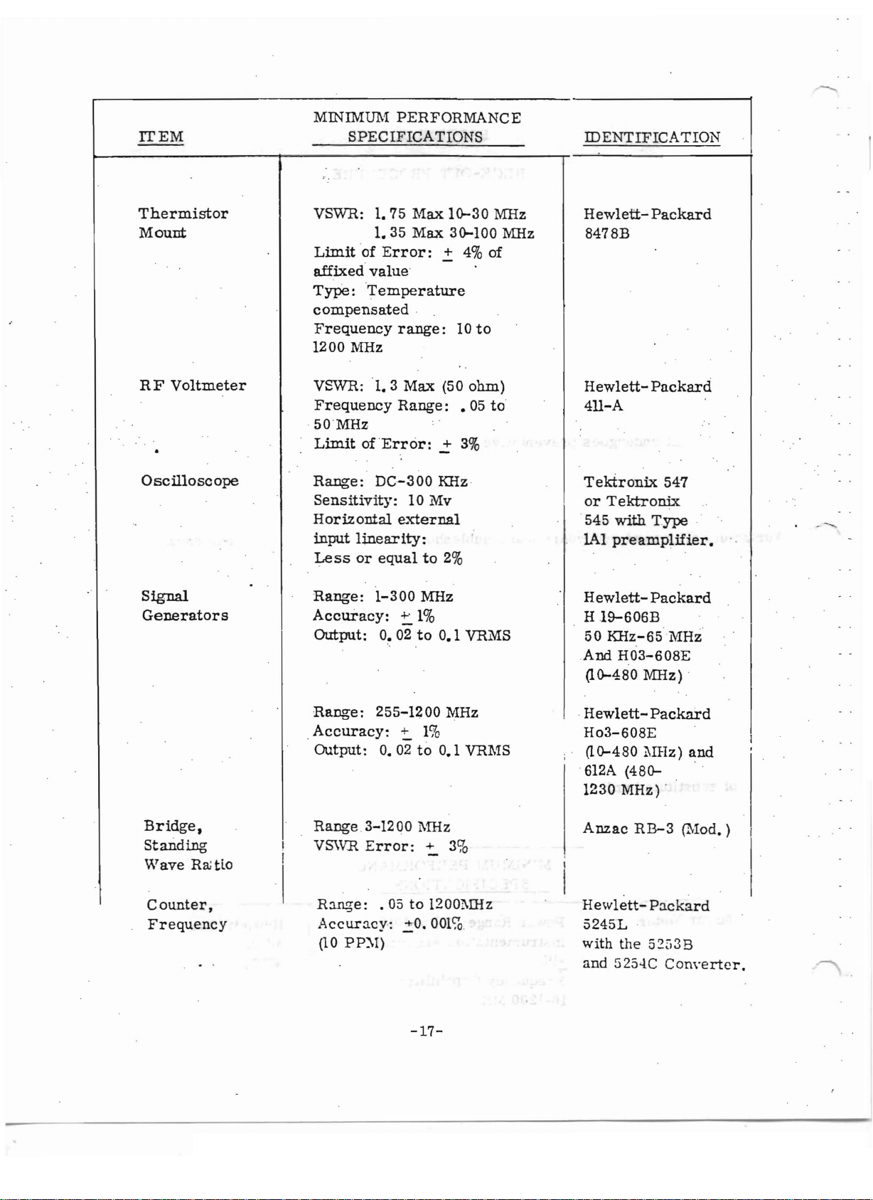
ITEM
MINIMUM
SPECIFICATIONS
PERFORMANCE
-
IDENTIFICATION
Thermistor
Mount
RF
Voltmeter
Oscilloscope
Signal
Generators
VSWR: 1. 75
Limito!
affixed
Type:
compensated
Frequency
1200
VSWR:
Frequency
·50"MHz
Limitof'Error
Range:
Sensitivity:
Horizontal
input
Less
Range:
Accuracy:
Output: O. 02to0.1 VRMS
value
Temperature
rvIHz
linearity:
or
Max
1.35
Max.
Error:
range:
1.3
Range:
DC-300
'
.
Max
:
10 Mv
2:
(50
.2"
KHz
external
equalto2%
1-300
MHz
::. 1%
1~30
3~100
4% of
10
to
ohm)
• 05
3%
MHz
:MlIz
to
Hewlett-
8478B
Hewlett411-A
Tektronix
or
Tektronix
545
Lo\l
Hew
H
19-606B
50
Kl!z-65
And H03-60BE
(1~480
with
pre
amplifier.
lett-
Packard
Packard
547
Type
Packard
MHz
IvIHz)
.
Bridge,
Standing
Wave
Counter,
Frequency
Ra
tlo
.
I
I
Range:
Accuracy:
Output:
Range
VS\VR
.3-1200
Error:
Range:
Accuracy:
(10 PP::\I)
255-1200 MHz
~
1%
0.02
to
0.1 VRMS
M:Hz
+ 3%
.05to1200l\lliz
.:!:O.
001~
-17-
HewlettHoS-G08E
(10-480
.
612A
1230 MHz) '
Anzac
Hewlett-
5245L
with
and
?11Hz)
(480- '
RB-3
the
52i
525..J.C
Packard
and
(Mod.)
Packard
J3B
Converter.
I .
I.
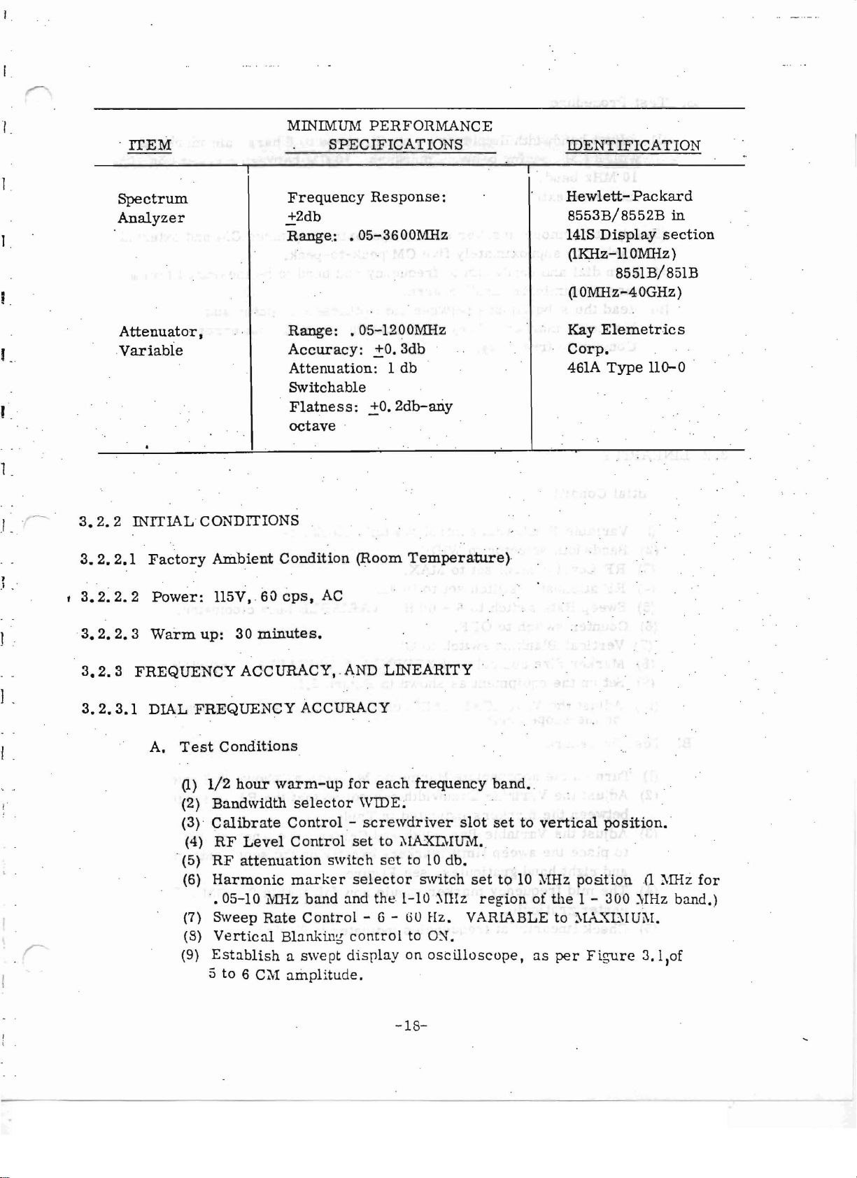
MINIMUM PERFORl\1ANCE
.
ITEM
1
Spectrum
Analyzer
J
Frequency
+2db
Range;
SPECIFICATIONS
Response:
.05-3600Mllz
IDENTIFICATION
I .
Hew1ett-
8553B/8552B
141S
Display
Packard
in
section
(1KHz-llOl\ffiz)
8551B/851B
(lOMllz-40GHz)
Attenuator,
Variable
Range:
.05-1200Mllz
Accuracy:
Attenuation:
.±0.3db
1 db
Corp.
461A
E1emetric
Type110-
s
°.
Kay
Switchab1e
Flatness:
.±0.2db-ariy
octave
•
.1 . ·
J .
3.2.2
3.2.
,
3.2.2.2
3.2.2.3
3.2.3
3.2.3.1
INITIAL
2.1
Factory
Power:
Warm
FREQUENCY
DIAL
A.
Test
-(5)
CONDITIONS
Ambient
115V. 60
up:
30
minutes.
ACCURACY,
FREQUENCY
Conditions
(1)
1/2
hour
(2)
Bandwidth
(3)
Calibrate
(4)
RF
Level
RF
attenuation
(6)
Harmonic
-. 05- 10 lvlliz
(7)
Sweep
(8)
Vertical
(9)
Establishaswept
Rate
5 to 6 C11
Condition
cps,
AC
ACCURACY
warm-up
selector
Contro1-
Control
marker
band
Control
Blanking
amplitude.
(Room
.AND
for
WIDE~
set
switch
selector
and
control
display
Temper-ature)
LINEARITY
each
frequency
.
screwdriver
to ;\IA.XL\IffiVI. .
set
to 10
db.
switch
the
1-10 :\IHz
- G -
GO
Hz.
to
O~.
on
oscilloscope,
.
band
•.
slot
settovertical
setto1011Hz
region
of
the
posit
1 -
position.
ton
300
VARIABLE to :'IA.."'{E\IUi\I.
as
per
Figure
ul :\IHz
:';IHz
3.l
,
·
for
band.)
of
-18-
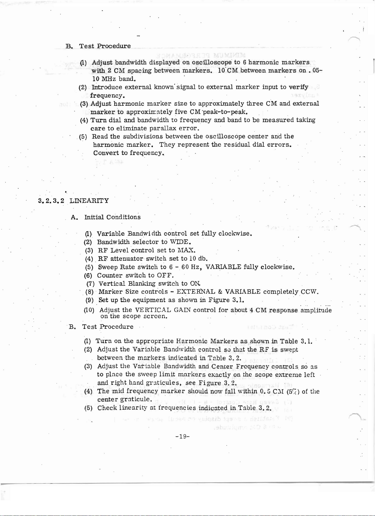
B.
Test
Procedure
(1)
Adjust
with2Cl\'1
10 MHz
(2)
Introduce
frequency.
(3)
Adjust
marker
(4)
Turn
care
0(5)
Read
harmonic
Convert
·0
3.2.3.2LlliEARITY
A.
Initial
bandwidth
spacing
band.
external
harmonic
to
approxirr
dial
and
to
eliminate
the
subdivisions
marker.
to
frequency.
Conditions
displayed
between
known'
marker
ately
on
oscilloscope
markers.
signaltoexternal
size
to
approximately
five
CM
'peak-to-peak,
bandwidthtofrequency
par
all.ax
error.
between
They
the
represent
to 6
10' CM
marker
and
bandtobe
oscilloscope
the
residual
harmonic
between
three
center
dial
markers
markers
on
inputtoverify
CM
and
external
measured
arid
taking
the
errors.
.05-
(1)
Variable
(2)
Bandwidth
(3)
RF
(4) 0
RF
(5)
Sweep
(6)
Counter
(7)
Vertical
(8)
Marker
(9) .
Set
(10)
Adjust
on
.
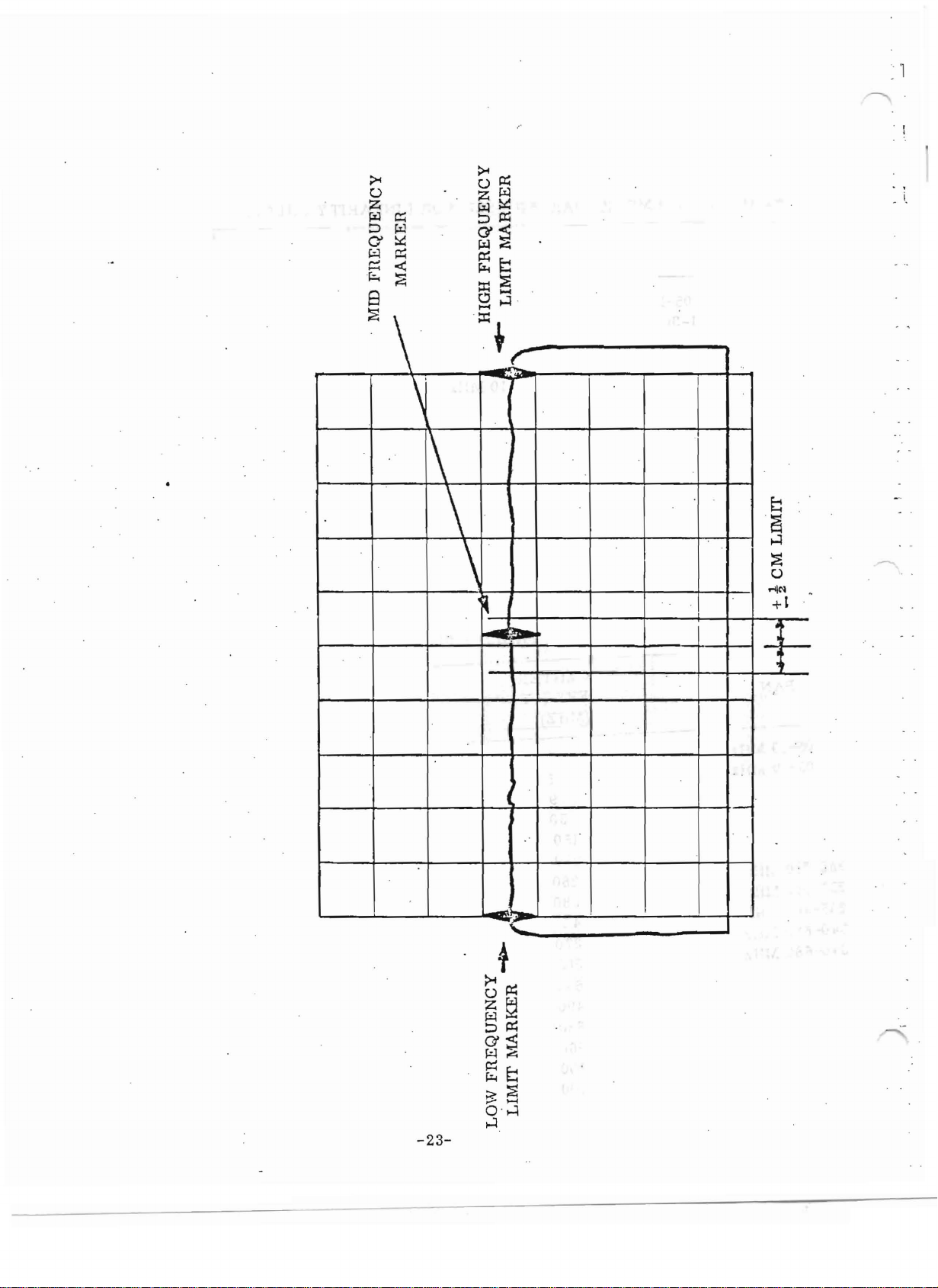
B.
Test
Procedure
(1)
Turn
(2)
Adjust
between
(3)
Adjust
to
place
and
(4)
The
centergrnttcule
(5)
Check
Bandwi
elm
selector
Level
control
attenuatorswitch
Rate
switch
switchtoOFF.
Blanking
Size
controls-EXTERNAL
up
the
equipment
the
the
on
right
mid
VERTICAL
scope
the
appropriate
the
Variable
the
markets
the
Var
the
sweep
hand
frequency
screen.
iable
gruticule
,
linearity
at
control
to
WIDE.
set
to l\IA.'\:.
set
to 6 - 60
switch
as
to 10 db.
to
shown
GAIN'
set
Hz,
ON.
control
Harmonic
Bandwidth
control
indicatedin'I'able
Bandwidth and
limit
frequencies
s ,
marker
markers
see
should
indicatedinTable
fully
clockwise.
VARIABLE
& VARL'\BLE
ill
Figure
for
.0 0 0
Markers
Center
exactly
Figure
now
3.1.
about
so
that
3.2.
Frequency
on the
3.2.
fall
within
fully
clockwise,
completelyCCW.
4 CM
as
showninTable
the
response
RFisswept
controls
scope
O.
ij
3.2.
extr
C:\I
(5C;C)ofthe
amplitude
3.1.
so
erue
0
as
left
-19-
c-...J
._ _
._.
...
......
-
I ·
I
'_ .oJ
-- ,
--<
~
'\
......
1520
I
l'-'
a
I
EXT
MARKERS
o 0
SWEPT
GENERATOR
FREQUENCY
v V H
IN
o 0 0 0 @
OUT
OUT
RF
OUT
I
DET
RF
0
I
,
I
.
, .
If
. 0
· V
0
,
SHORT
,LOW
.y.
.\ol-.
VSWR
CABLE
,..
· I
1520
EXT
MARKERS
o 0
SWEPT
GENERATOR
FREQUENCY
v V H RF
IN
o 0
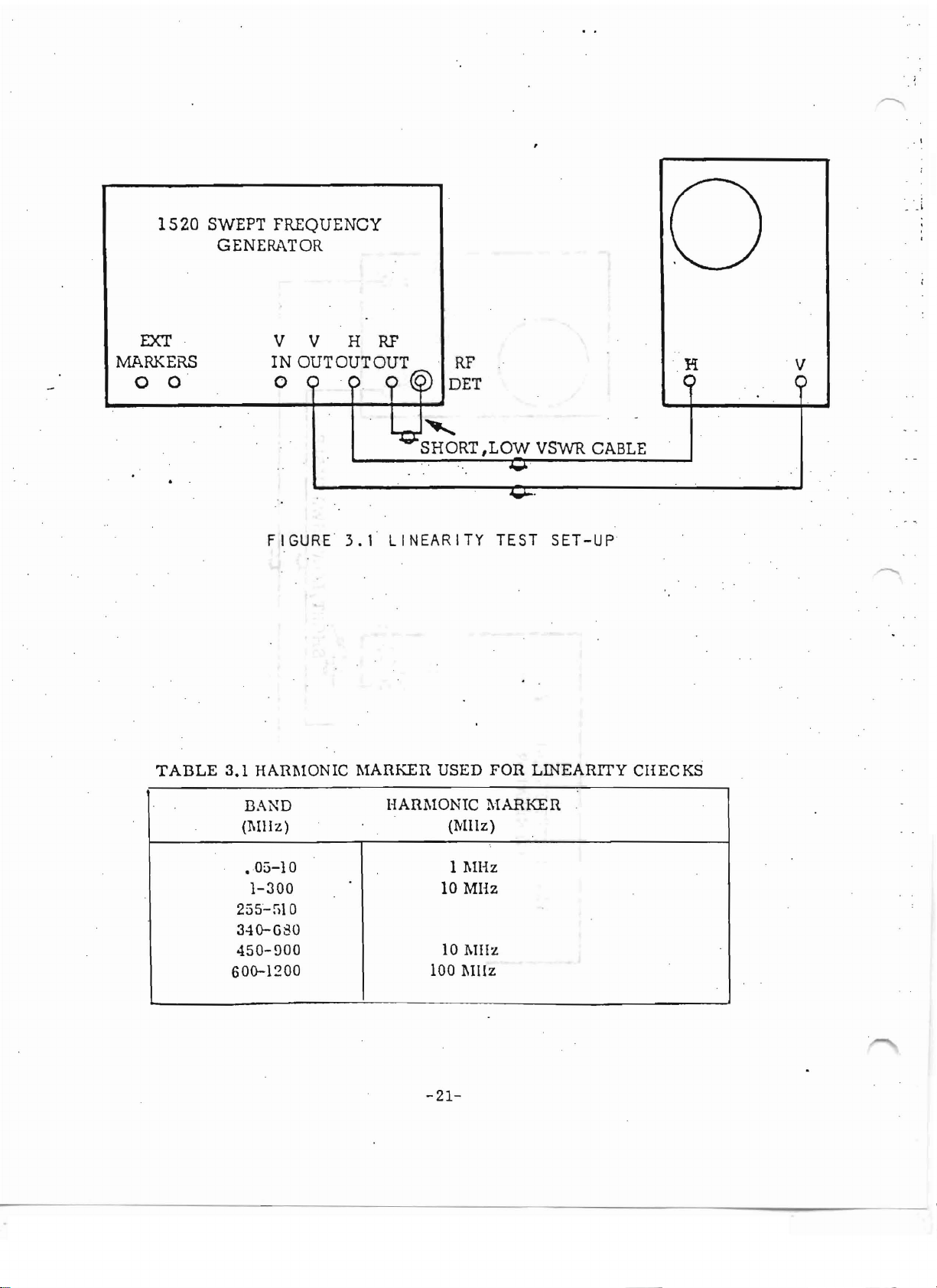
FIGURE
OUTOUTOUT
:')
.
3.1
LINEARITY
~
~
..........
SHORT
RF
DET
,LOW
o4wI-
TEST
o
v
o
VSWR CABLE
.
SET-UP
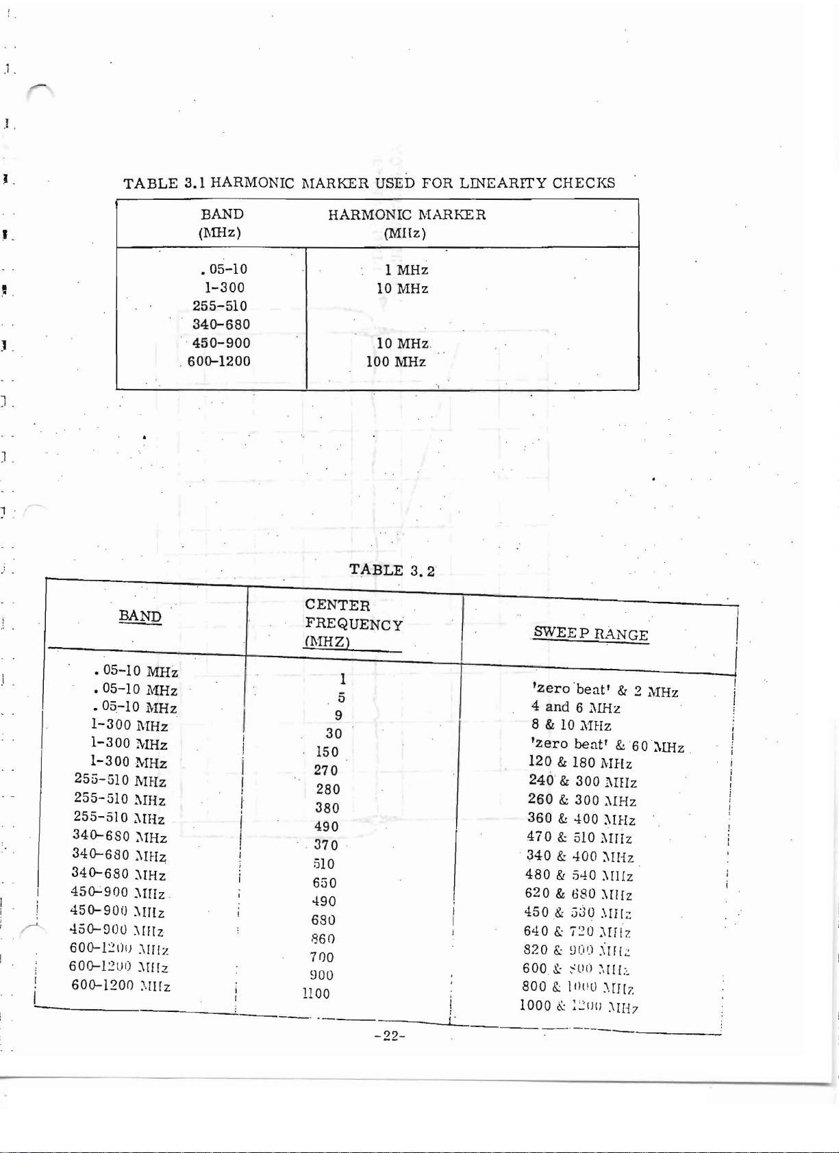
TABLE
3.1
HARl\lONIC
BAND
(~I1I
z)
.05-10
1-300
255-;;10
340-G80
450-900
600-1200
MARKER
HARMONIC
USED
(MHz)
1 l\lHz
10 MHz
10 I\lIIz
100 111lz
-21-
FOR
LINEARITY
l\lARKER
CHECKS
I
i .
.1
.
.1
,
J .
I
J .
J .
1 '
TABLE
3.1
HARMONIC
BAND
(MHz)
•
05-10
1-300
255-510
340-680
.
450-900
.
600-1200
MARKER
USED
FOR
HARMONIC lV1ARKER
(MHz)
1
MHz
10
MHz
10
MHz
100
MHz
TABLE
3.2
LlliEARITY
.
, '
CHECKS
.1
J .
CENTER
FREQUENCY
(MHZ)
1
5
9
30
150
270
280
380
490
. .
370
.
510
650
490
680
,'360
7
no
900
1100
..
-------L_
-22-
SWEEP
"zero 'be a t' & 2
4
and
8 & 10
'zero
120&180
240
260&300
360
470
.
340
480
620&680
450.&
640
820
600
.
800&:I
!
I '
1000
RANGE
6 l\IHz
7\'IHz
beat'
l\JHz
&
300
l\IIIz
:'IIHz
&
400
:'11Hz
& 510
&
400
:\uiz
:\IHz
& 5-!0 :'IIIIz
:\1/[z
530 .\IIr
&:
'i
~
0 ;,Iflz
&:
~O')
.\[f
So:
~
ll ()
~\[/l:
(lOO
;..
[J [/:
~
:~lJlJ
:"IH7
MHz
&60:\IHz
;::
1.::
~
.
.05-10
.05-10
.05
1-300
1-300
1-300
BAND
MHz
MHz
.-10 MHz
1\1Hz
MHz
MHz
MHz
l\IHz
~IHz
:\lHz
:'IIHz
:'11Hz
:'Imz .
:'Imz
:\IIlz
:\Ir!z
.
i
I
I
I'
,
I
I
I
•
255-510
255-510
255-510
340-680
340-680
340-680
450-900
450-900
450-900
60o-1~1l1)
suo-Izu o :'I[l[z
60o-120()
;.[I[z
L
--_
FIlEQUENCY
MARKER
MID
~
~
»>
~
l\1ARKER
FREQUENCY
LIMIT
HIGH
...
,
~
.
~
-
)
. .
LIMIT
~
.
,~
J
-.:>-
CM
tJ
.
..
('
MARKER
FREQUENCY
LIMIT
I
I
~
W
LOW
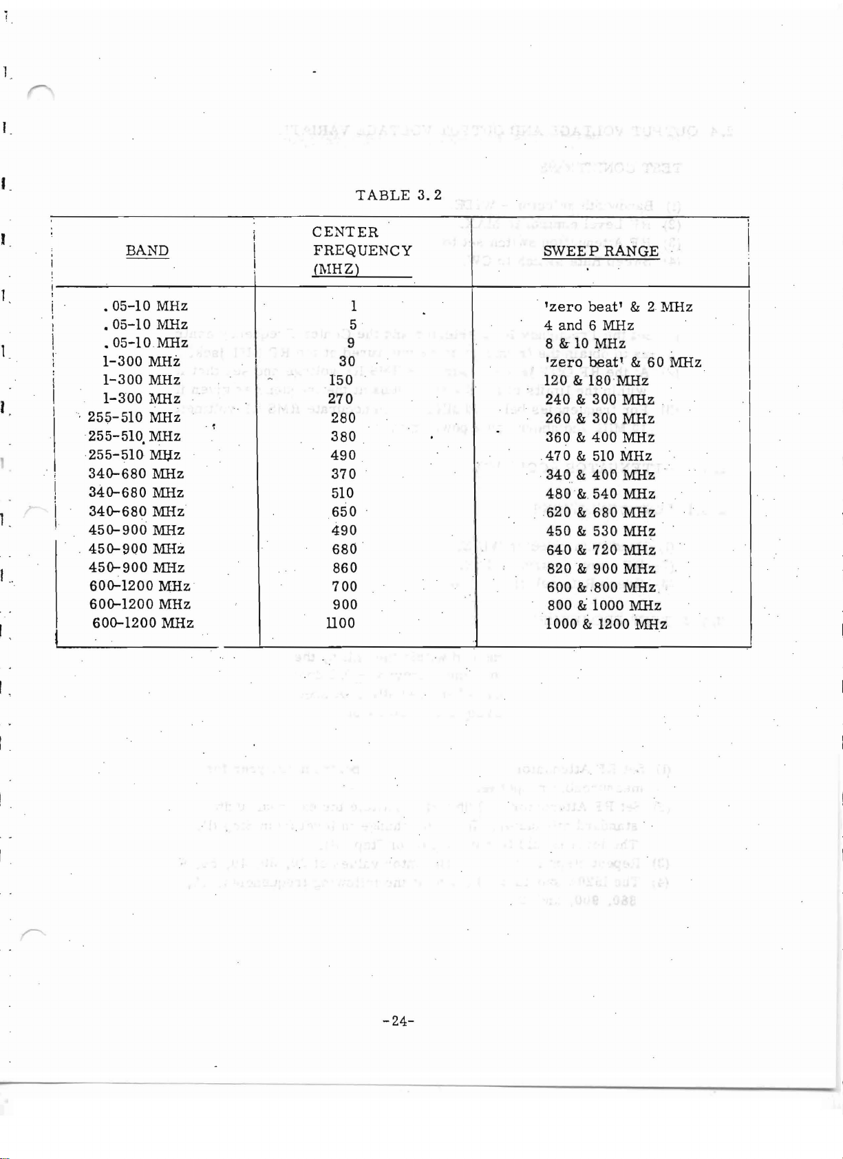
TABLE
3.2
i
I
BAND
CENTER
FREQUENCY
(l\1HZ)
SWEEP
RANGE
i
I
.05-10
I
i
I
,.
;
:
I
I
I
I
I
I
i
i
!
1
.'
.05-10
.05-10
1-300
1-300
1-300
,
255-510
·255- 510
255-510
340-680
340-680
340-680
450-900
.
450-900
450-900
600-1200
600-1200
600-1200
MHz
MHz
MHz
MHz
MHz
MHz
MHz
MHz
..
MUz
MHz
MHz
:MHz
:MHz
:MHz
MHz
MHz
MHz
MHz
1
5
9
30
150
270
. l
·
280
380
490
370
510
650
490
680
860
700
900
1100
'zero
4
8
'zero
120
240&300
260&300
360&400
.470
·34 0 &
480&
620&680
450&530
640&720
820&900
1000&1200
beat'
and 6 MHz
& 10
MHz
beat'
& 180
& 510
400
540
600
&,800
800&1000
&
&
MHz
MHz
MHz
MHz
MHz
MHz
MHz
MHz
MHz
MHz
MHz
MHz
MHz
MHz
21'lliz
60
Mflz
. .
. .
I
I
I
.\
I
-24-
·.'.
~
.
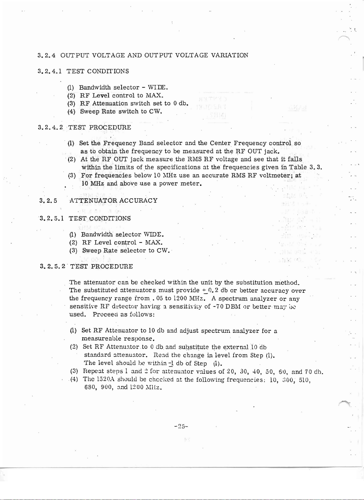
3.2.4
3.2.4.1
3.2.4.2
3.2.5
3.2.5.1
OUTPUT
TEST
(1)
(2)
(3)
(4)
TEST
(1)
CONDITIONS
Bandwidth
RF
RF
Sweep
PROCEDURE
Set
the
astoobtain
.(2) At
the
within
(3)
For
10
MHz
ATTENUATOR
TEST
CONDITIONS
VOLTAGE
selector
Level
control
Attenuation
Rate
switch
Frequency
the
RF
OUT
the
limits
frequencies
and
above
ACCURACY
AND
OUTPUT
- WIDE.
to
l'iIA..",{.
switch
to CWo
Band
frequency
jack
measure
of
the
below
useapower
VOLTAGE
set
to0db.
selector
to
be
measured
the
specifications
1011Hz
use
meter.
and
RMS
the
an
accurate
VARIATION
Center
at
the
RF
voltage
at
the
frequencies
Frequency
RF
OUT
and
RMS
RF
control
jack
see
thatitfalls
given
voltmeter;
so
•
ill
Table
3.3.
at
3.2.5.2·
(1)
Bandwidth
(2)
RF
(3)
Sweep
TEST
The
attenuator
The
substituted
the
frequency
sensttive
used.
(1)
Set
measureable
(2)
Set
standard
The
(3)
Hepcat
(4)
The
680,
selector
Level
Rate
control
selector
PROCEDURE
can
attenuatorsmust
range
UF
detector
Proceed
RF
as
Attenuatcr
response.
RF
Attenuatcr
attenuato
level
should
steps1and:2for
1520A
900,
should
and
\VIDE.
-
MAX.
to
be
checked
from.
having: a
follows:
to 10 db
to °db.
r,
be
within
be
checked
l:~OO
i\Illz.
CWo
within
05to1200
sens'it
and
and
Read
the
j.
atte
nuntor
the
unit
provide:::..
0.2
MHz.
ivity
of
adjust
spectrum
substitute
changeinlevel
db of
Step
values
at
the
following
by
the
substitution
db
or
A
spectrum
-70
DEl';!orbetter
analyzer
the
external
from
(1).
of :20, 30,
frequencies:
better
analyzer
10
Step
accuracy
for
db
-1:0,
method.
may
a
(1).
50,
10,
over
or
any
;JC
61),
and
~100:
70
510,
dh,
,.
I.
I.
J .
.
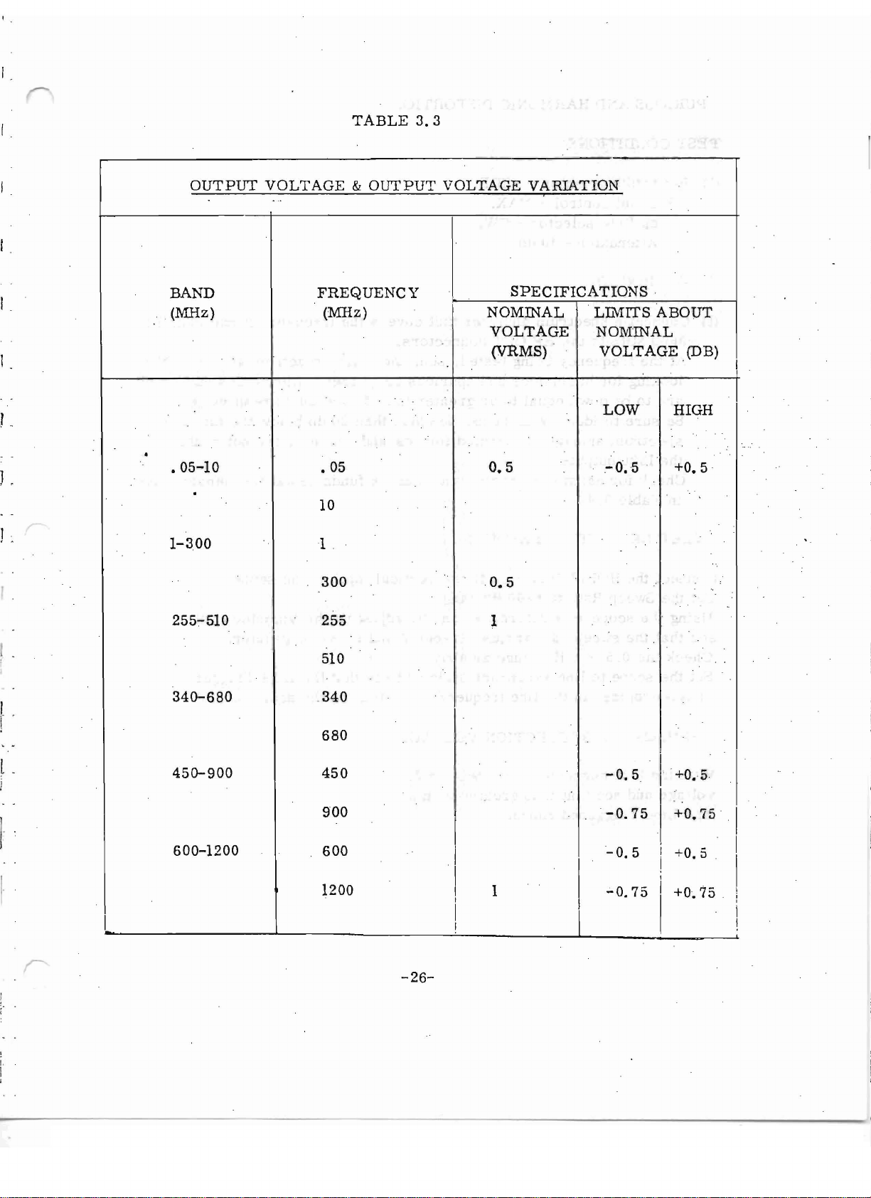
OUTPUT
BAND
(MHz)
.05-10
.
TABLE
VOLTAGE&OUTPUT
...
FREQUENCY
(MHz)
.05
10
3.3
VOLTAGE
NOMINAL
VOLTAGE
(VRMS)
0.5
VARIATION
I
SPECIFICATIONS
t.rxrrrs
NOMINAL
VOLTAGE
LOW
-0.5
.
ABOUT
(DB)
I
HIGH
+0.5
1.
I· .
1-300
255-:-510
340-680
450-900
1
300
255
510
.340
680
450
0.5
1
-0.5
I
I
+0.5
I
900
600-1200
600
1200
I
I
I
I
1
I
I
I
-0.75
-0.5
';'0.75
I
i I
I
I
I
I
I
+0.75
+0.5
+0.75
I
I
I
,
i
I
I
-26-

I
3.2.
G"
SPURIOUS AND HARl\'lONIC DISTORTION
3.2.6.1
3.2.
6.2
3.2.7
TEST
(1)
(2)
(3)
(4),
TEST
(1)
(2) At
(3) Be
CONDITIONS
Bandwidth
RF
Level
Sweep
RF
Rate
Attenuator
PROCEDURE
Connectaspectrum
3600
MHz to
the
frequency
looking
are
to
sure
for
be
to
spectrum
the
1520
output.
(4)
Check
in
SWEEP
for
Table
REPETITION
selector
control
selector':"
- 10 db.
the
harmonics
down
equaltoor
identify'
analyzer
harmonics
3. 4.
- \VIDE.
-l\lAt"X.
CWo
analyzer
that
covers
RFOUT·connectors.
being
tested,
and
spurious
scan
greater
all
responses,less
generated
and
FREQUENCY
images
spurious
.
the
the
entire
responses.
than
30
than
and'spurious
at
the
fundamental
frequency
spectrum
and
20 db
30
db
range
of
Harmonics
respectively.
below
the
are
notcoiifused
frequencies
of . 05 to
105
to.
3GOO
IVIHz
and
spurious
fundamentalso.
with
given
3.2.7.1
3.2.7.2
3.2.7.3
3.2.7.4
3.2.7.5
3.2.'8
Connect
Set
Using
see
Check
Set
is
synchronized
the
the
Sweep
the
that
the
the
the
scopetoline
scope
0.5
HORIZONTAL
With
tile
1520
voltage
and
Line
and
'I'r
HORIZ
Rate
OUT
to
6-60Hz
jacktothe
asareference,and
sweep
rate
- 6 Hz
varies
range
synchronization
to
the
line
DEFLECTION
connected
see
that
izzcr-ed
~o
as .in
it
is
runzes
. 0 •
range.
between6and
as
above.
frequency
VOLTAGE
Section
greater
vertical
than
"
by
adjusting
and
( no
3.2.7,
5 V
see
drift
inputofthe
the
60 Hz
that
check
on
or
the
the
the
peak-to-peak
scope.
Variable
greater.
Line
Triggei'ed
scope)ata
amplitude
on
the
control,
GO
of the
0.5-G,
r-ange
Hz
6-60,
rate.
sweep
-'27-
 Loading...