

Page 1
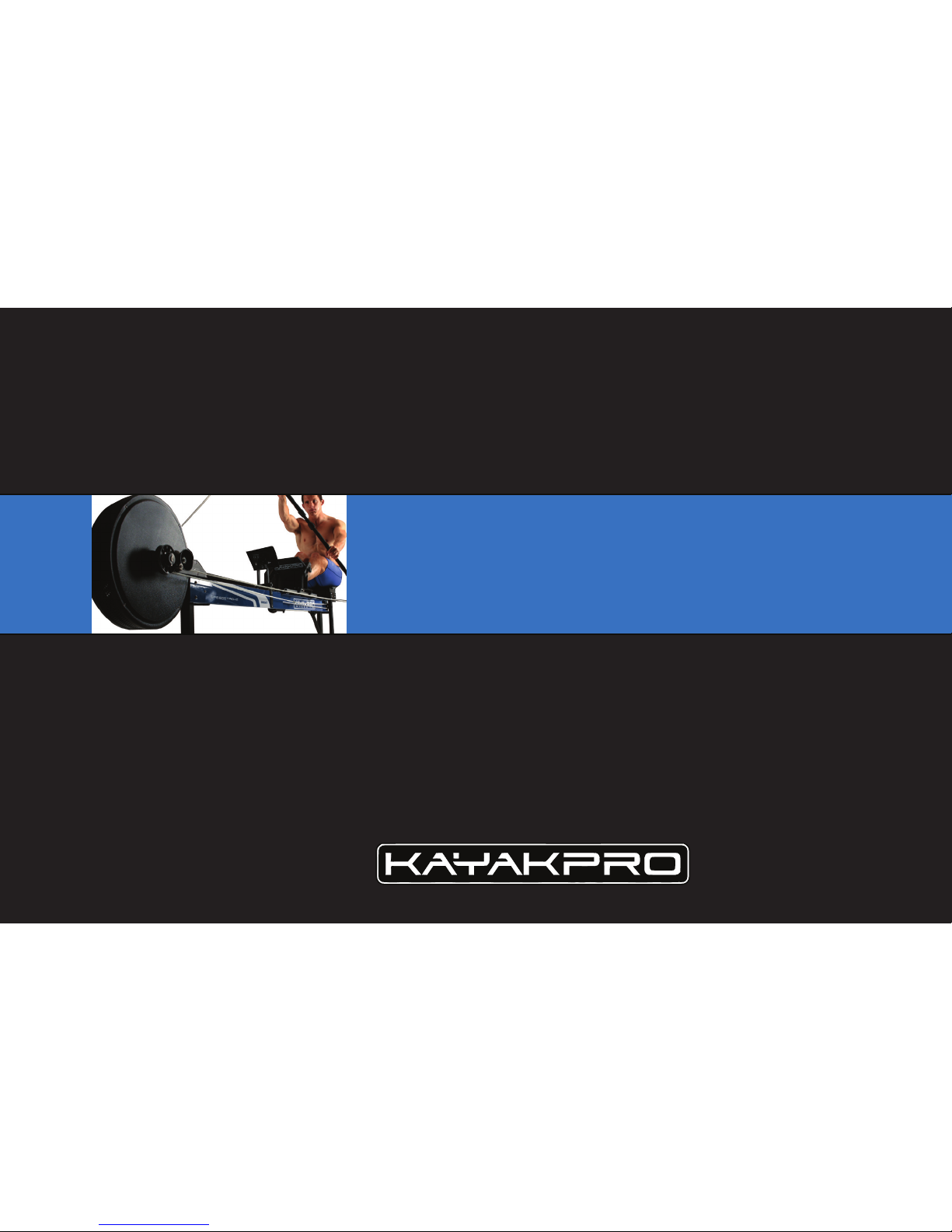
k1 assembly
instruction manual: How to put together your
KayakPro K1 SpeedStroke Ergometer
Page 2
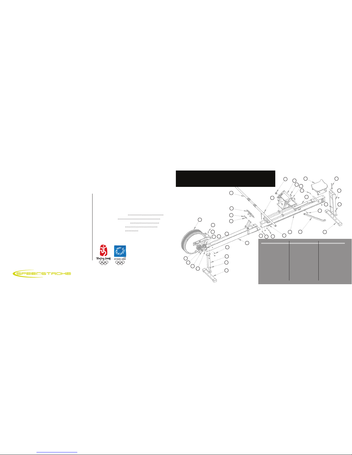
name
fan (1)
m8 x 20 (2)
guide wheel (2)
shaft-43 (2)
shaft-55(2)
m6 x 12 (4)
clutch wheel
m20 washer (6)
lock ring (4)
rear feet (1)
m8 x 16 (8)
name
front stand (1)
front feet (1)
kp1 shaft (1)
console (1)
m8 x 80 (1)
m8 washer (2)
front frame (1)
m8 nut bn (1)
m8 nut n (2)
m6 nut bn (2)
m8 x 120 (3)
name
m8 x 20 (2)
footrest (1)
m6 x 16 (8)
m8 nut snc (1)
rear frame (1)
sprit (1)
seat (1)
m6 x 20 (4)
rear stand (2)
m8 x 35 (2)
adjust-belt (1)
no
12
13
14
15
16
17
18
19
20
21
22
no
1
2
3
4
5
6
7
8
9
10
11
no
23
24
25
26
27
28
29
30
31
32
33
1
2
Serious injury can occur if the following precautions
are not observed.
1. Always consult your physician prior to undertaking any
exercise regimen. A medical exam is advised.
2. Keep head, limbs, fingers, and hair clear of all moving
parts and flywheel cage.
Please note: SpeedStroke requires a working area of
3.3m x 2m x 2.1m (132” x 78” x 82”).
3. Inspect machine prior to use. Do not use the machine if
it appears damaged or inoperable.
4. Contact manufacturer if machine is broken or jammed.
5. Use machine only as intended.
6. Do not modify the machine.
7. Children must not be allowed near this machine.
8. Teenagers must be supervised in the use of this machine.
9. By using SpeedStroke GYM the user accepts all and full
responsibility for self.
safety precautions
safe operation and use
table of contents
KayakPro k-1 ergometer
k-1 overview | parts
k-1 assembly
rope, bungee & paddle
notes for best use
on-board console
GYM
off cial supplier of kayak
ergometers to the 2004
Athens and 2008 Bejing
olympic games
i
001
3
4
5
6
7
8
9
6
11
12
11
13
18
14
15
16
17
19
20
21
22
33
27
28
32
10
23
24
25
26
30
33
32 11
31
2229
k1 assembly overview
2
3-8
9-12
13-15
see seperate manual
front cover:
Ed McKeever | European & World Champion
Page 3
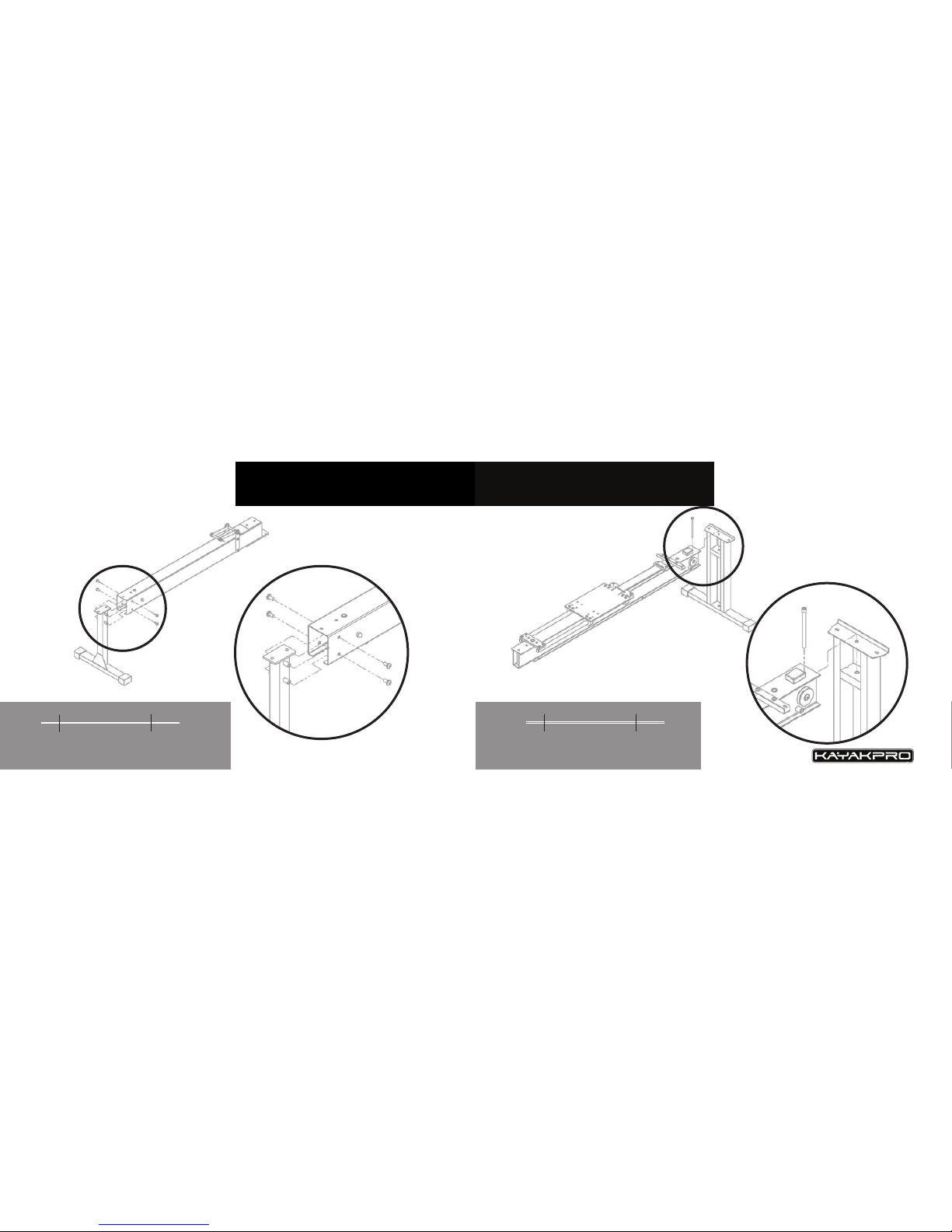
f g.
a
i part
screw: m8 x 16
count
4
f g.
b
i part
screw: m8 x 120
count
1
www.kayakpro.com
004
A
003
A
B
B
k-1 assembly step 2
step 1 k-1 assembly
Page 4
www.kayakpro.com
006
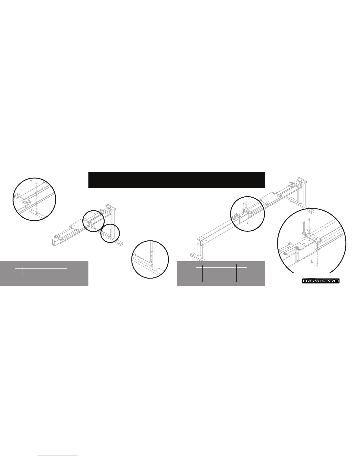
step 3 k-1 assembly
k-1 assembly step 4
f g.
c
d
i part
screw: m6 x 12
screw: m8 x 35
count
2
1
005 www.kayakpro.com
f g.
e
i part
screw: m8 x 120
gasket: m8
screw: m6 x 20
nut: m6
count
2
2
2
2
D
C
D
C
Page 5
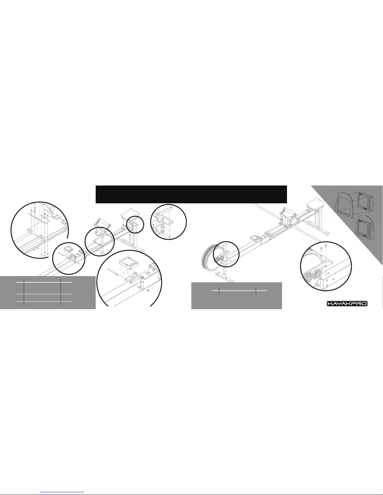
f g.
f
g
h
i part
screw: m8 x 80
gasket: m8
nut: m6
screw: m6 x 16
nut: m6
nut: m6
count
1
2
1
8
8
4
step 5 k-1 assembly
F
H
H
F
G
G
k-1 assembly step 6
f g.
i
i
part
screw: m8 x 20
count
2
I
I
008
Page 6
what you will need before beginning
2 sets of ropes (the other 2 ropes in the package
are spares- as is the additional bungee)
3 peices of the paddle shaft
The smallest Allen wrench in the set provided.
Please ensure that during transit the bungee cord
on this central roller is still located on the roller
wheel here and has not slipped onto the axle.
(see image above)
The following instructions from this point forward,
assume the internal bungee arrangement is in place
within the body of the SpeedStroke at arrival. If this
is not the case, please do not hesitate to contact us
in order to assist you further.
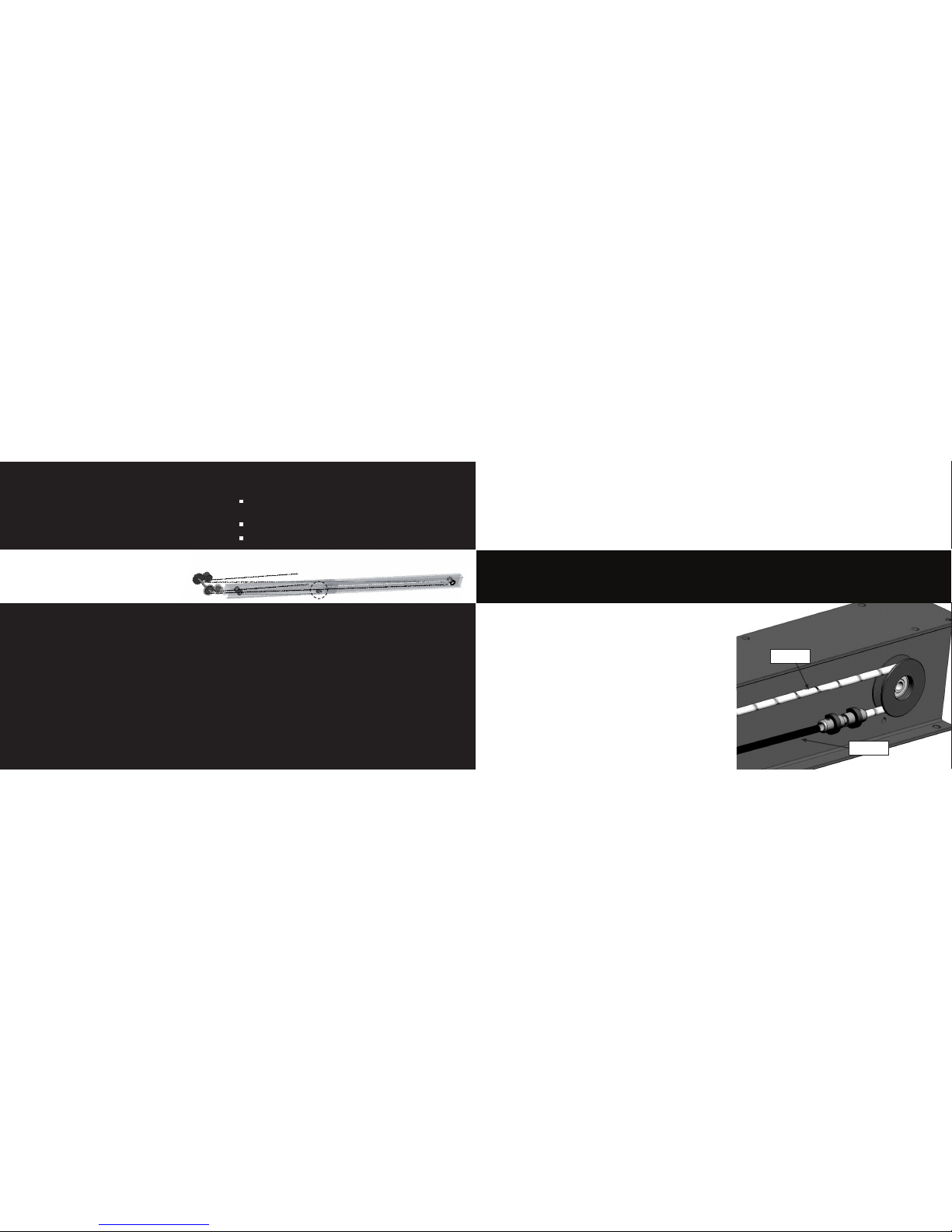
Step 1: On one side of the SpeedStroke, run the bungee cord
around the roller on the back of the machine, under the seat. It
should go from the top of the roller to the bottom. (See image.)
PLEASE NOTE: You may need to remove the aluminum anti-
twist connector from the bungee, to install the rope / bungee
system. Run bungee around rear roller (again, from top to bottom), and then reattach anti-twist unit by tightening recessed
screw fully. (See image.) The anti twist connector has different
recessed screws for the rope and for the bungee end- If one
screw is found to be protruding please rotate the Anti-twist
connector and re-attach.
Step 2: Repeat on the other side.
pre-instruction
Once the main structure of the SpeedStroke is
assembled, it should remain “upright.” Do not
place the machine on its side or upside down
during final assembly.
www.kayakpro.com
010
rope bungee paddle shaft conf guration i
rope bungee paddle
instructions steps 1 & 2
bungee
rope
Page 7
www.kayakpro.com
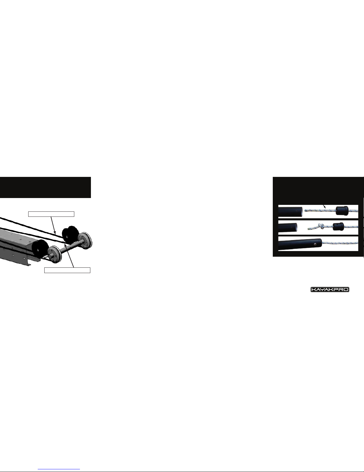
Step 3: On one side of the SpeedStroke, attach the
rope to the anti-twist unit. Use the smallest Allen
wrench provided to tighten the screw fully around the
rope. When you are done, the rope should be attached
to the bungee by the antitwist connector.
(As seen on page 10.)
Step 4: Repeat on the other side.
Step 5: On one side of the SpeedStroke, run the rope
around the rollers at the front of the machine, near
the Flywheel. Do this as pictured in the image below.
The rope travels around the bottom of the silver front
catch roller, exits the top of that roller, and then
(under) the bottom of the black guide roller. The rope
should exit toward the back of the machine (where the
seat is). You will leave it on the floor for now.
Step 6: Repeat on the other side.
steps 3 - 6
rope bungee paddle
you can adjust the length of the rope here
Step 7: You will now assemble the paddle shaft (3
pieces). The piece without the ferrule installs in the
middle. The other two pieces install on the outside
with the screw pointed outward. For now, place the
paddle shaft in its narrowest position, so it is as short
as possible.
Step 8: Unscrew the tip (insert) of the shaft on one
side and remove the insert. Run the rope on that side
through the hole in the insert. Tie a knot on the rope
on the “inside” of the tip, leaving about 10 cm of loose
rope for placement inside the shaft. (It does not have
to be exactly 10 cm, but you should measure from the
knot to the end - you will need to match this on the
other side.) The screw should now be attached to the
front side of the shaft.
Step 9: Repeat on the other side.
Step 10: Once the paddle shaft is attached on both
sides, use the two ferrules to adjust the length of the
shaft to your own personal preference. Make sure the
distance from the ferrules to the end of the shaft is
uniform on both sides. Adjusting the length of the
shaft will alter the paddling resistance; the longer the
shaft, the greater the resistance, the shorter the shaft,
the less the resistance.
steps 7 - 11
rope bungee paddle
Step 11: The shaft-length adjustment will also allow
you to customize SpeedStroke to replicate precisely
the paddling “feel” of your own boat.
from rear of speedstroke
to the end of the paddle shaft
012
011
Page 8
The shaft length and the Set-able resistance lever on the
flywheel should be set in balance with one another in order
to provide the resistance level that best mimics your boat
and paddle set-up.
As an approximate guide, a SpeedStroke shaft length of
approx: 170 cm- (67 Inches) should equate to approx 219220 cm paddle length, with a medium size blade area.
Do not extend the paddle shaft length over the “Max”
length marks.
When extending the paddle shaft length it is very important
that the shaft length is adjusted equally,( in relation to the
shaft insert piece) – if this is not done – bending of the shaft
[for which we cannot be responsible] may occur.
When short or intense efforts are being done on SpeedStroke
GYM, usually over 125 strokes per minute (spm), and up to
180 spm, as would be typical on a 200m workout- we restrict
the continuous rope action, in order to be able to achieve the
higher stroke rate needed.
SpeedStroke’s action is made better by the “continuous
rope” system that is in place on your Ergometer, this thereby
allows a more “real” paddling action. This continuous rope
system allows better end-of-stroke recovery, and greater
freedom to rotate whilst paddling.
When paddling at an Ultra high frequency- At a stroke rate
above approx. 125 spm the rope in its continuous rope configuration will not allow recovery sufficiently quickly to allow
you to paddle at a higher frequency.
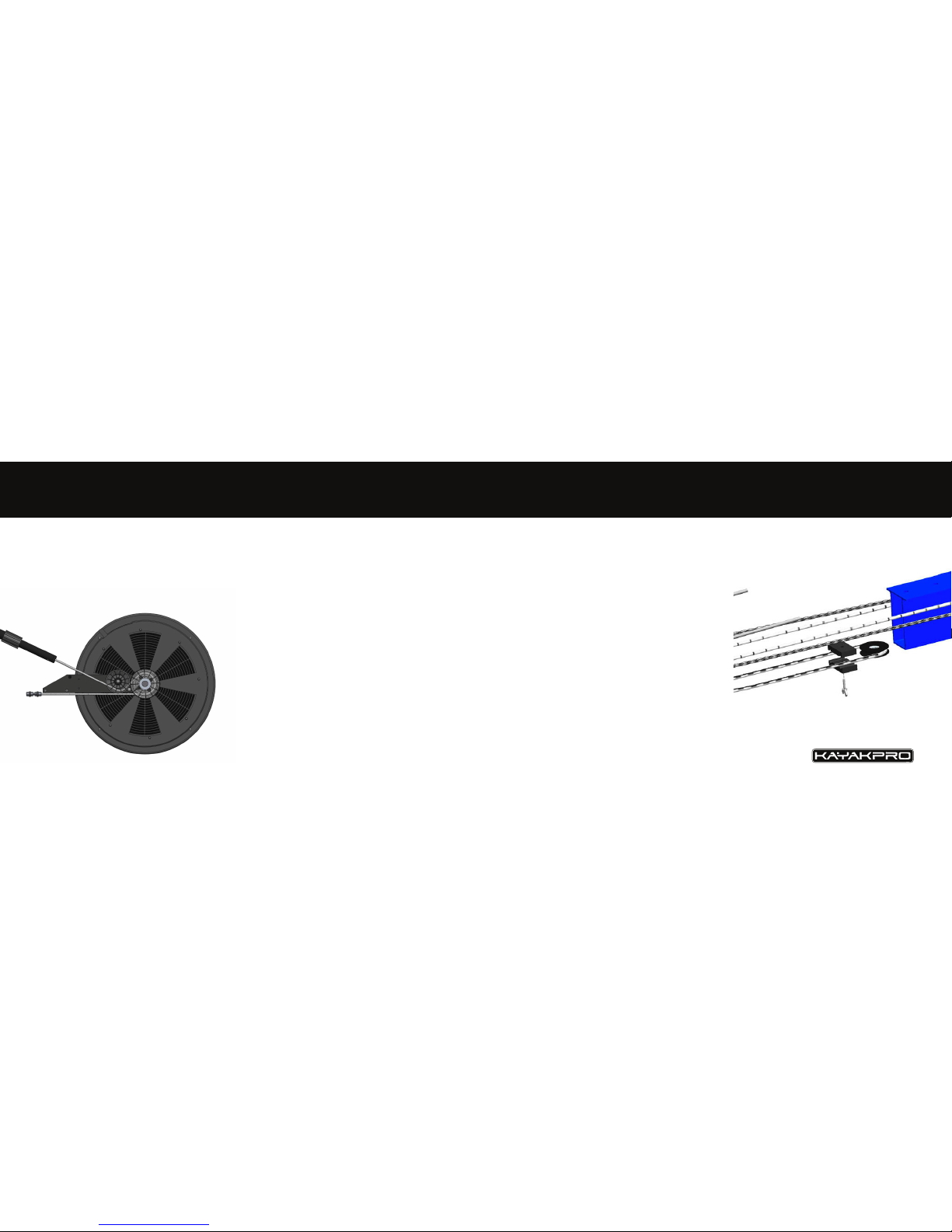
However- by the addition of a simple bungee clip system
(which attaches to the underside of the SpeedStroke GYM
bungees). See image right- This High Frequency adjuster will
allow you to paddle at frequencies of up to 180 strokes
per minute.
www.kayakpro.com
notes for best use
paddle shaft
notes for best use
ultra high frequency stroke rates
014
013
Page 9
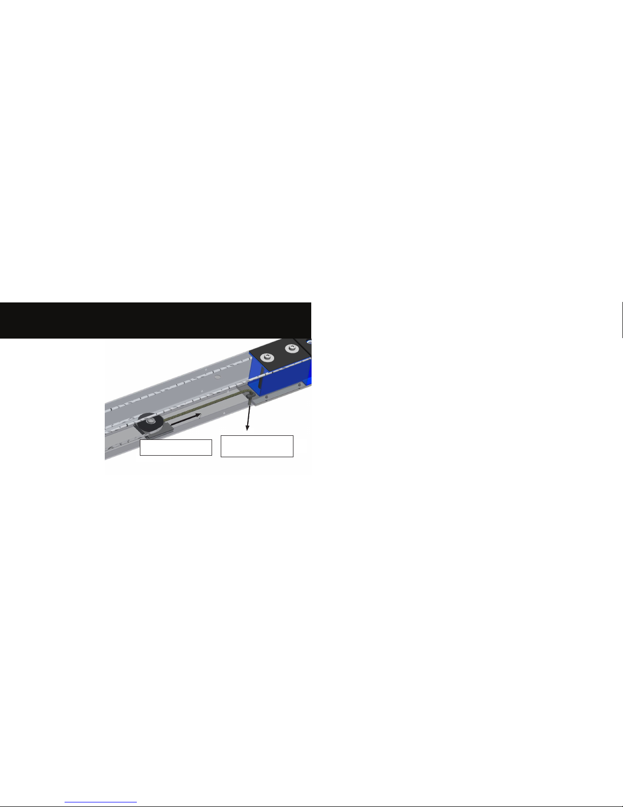
Another mechanism in order to
ensure maximum connectivity of
the paddling action is the rope
tension adjuster, located under the
Ergometer (see image).
Simply pull the rope and clamp
toggle downward to increase the
rope tension and in reverse simply
release the rope clamp toggle to
reduce the rope tension.
Again the rope tension preferences
should be adjusted in balance and
harmony with the ability to shorten
the total rope length in the [shaft
rope] figure see page 012.
www.kayakpro.com
notes for best use
tension adjuster
direction of movement
of tensioner
pull rope downward
to increase the tension
on the tension roller
015
Page 10
contact us | www.kayakpro.com | +1 914 740 5055 | sales@kayakpro.com
KayakPro USA LLC
6538 Collins Ave Suite 306
Miami Beach, FL 33141
For a full list of international dealers go to:
www.kayakpro.com/speedstrokegym/dealers.php
Offical suppliers of kayak egrometers to the
2004 Athens & 2008 Beijing Olympic games.
GYM
 Loading...