


Operating Instructions and Manual
Kawashima
Guaranteed Pure
Sine Wave
INVERTER GENERATOR

Kawashima
We Appreciate Your Business.
Thank you and congratulations for choosing Kawashima.
You have invested in a machine that will last a lifetime if you follow
strictly the maintenance and care guidelines set out in this manual.
This Operating Manual has been designed to instruct you on the
correct use and operation of your Kawashima product. Your
satisfaction with this product and its safe operation is our ultimate
concern. Therefore please take the time to read the entire manual,
especially the Safety Precautions. They will help you to avoid
potential hazards that may exist when working with this product.
.
WARNING!
READ AND UNDERSTAND ALL SAFETY PRECAUTIONS IN THIS MANUAL
BEFORE OPERATING. FAILURE TO COMPLY WITH INSTRUCTIONS IN THIS
MANUAL COULD RESULT IN PERSONAL INJURY, PROPERTY DAMAGE,
AND/ OR VOIDING OF YOUR WARRANTY. KAWASHIMA WILL NOT BE
LIABLE FOR ANY DAMAGE BECAUSE OF FAILURE TO FOLLOW THESE
INSTRUCTIONS.

Table of Contents
1. SECTION 1: SAFETY INSTRUCTIONS AND WARNINGS .................... 1-1
1.1 Symbol Usage ..........................................................................................1-1
1.2 General Safety Precautions .....................................................................1-2
2. SECTION 2: CONTROLS AND FEATURES ..........................................2-1
2.1 Generator ................................................................................................2-1
2.2 Control Panel ..........................................................................................2-2
2.3 Control Functions ....................................................................................2-3
3. SECTION 3: GETTING STARTED .........................................................3-1
3.1 Unpack the Generator .............................................................................3-1
3.2 Adding Engine Oil ...................................................................................3-1
3.3 Adding Fuel ............................................................................................. 3-2
3.4 Starting the Engine .................................................................................3-4
3.5 Stopping the Engine ................................................................................3-6
4. SECTION 4: ELECTRICAL CONNECTION ........................................... 4-1
4.1 Capacity .................................................................................................. 4-1
4.2 Power Maintenance ................................................................................ 4-1
4.3 Connecting Electrical Loads .................................................................... 4-1
4.4 Battery Charging……………………………………………………………….4-2
4.5 Wattage Reference Guide…………………………………………………….4-3
5. SECTION 5: MAINTENANCE ................................................................. 5-1
5.1 Periodic Maintenance .............................................................................. 5-1
5.2 Spark Plug Maintenance ......................................................................... 5-2
5.3 Engine Oil Replacement ......................................................................... 5-3
5.4 Air Filter Maintenance ............................................................................. 5-4
5.5 Muffler Screen & Spark Arrestor Maintenance ........................................ 5-5
5.6 Fuel Filter Maintenance ........................................................................... 5-6
6. SECTION 6: STORAGE .........................................................................6-1
6.1 Long Term Storage ................................................................ .................6-1
7. SECTION 7: TROUBLESHOOTING AND SPECIFICATIONS ...............7-1
7.1 Troubleshooting Diagram ........................................................................7-1
7.2 Fuel Filter Maintenance ...........................................................................7-2
7.3 Specifications ..........................................................................................7-3

1-1
SECTION 1:
SAFETY INSTRUCTIONS AND WARNINGS
1.1 Symbol Usage
This manual contains important information that you need to know and understand
in order to assure YOUR SAFETY and PROPER OPERATION OF EQUIPMENT.
The following symbols help you recognize this information. Please read the
manual and pay attention to these sections.
Save These Important Safety Instructions!
Read and understand all of these safety instructions. Be sure to
retain them for future use.
WARNING!
WARNINGS INDICATE A CERTAINTY OR STRONG
POSSIBILITY OF PERSONAL INJURY OR DEATH IF
INSTRUCTIONS ARE NOT FOLLOWED.
CAUTION:
CAUTIONS INDICATE A POSSIBILITY OF EQUIPMENT
DAMAGE IF INSTRUCTIONS ARE NOT FOLLOWED
PROPERLY.
Note:
Notes give helpful information
Gasoline powered and electrical generating products can cause serious injury or
death, or damage to other equipment or property, if the operator does not strictly
observe all safety rules and take precautionary actions.

1-2
1.2 General Safety Precautions
WARNING!
FAILURE TO FOLLOW THESE INSTRUCTIONS CAN
RESULT IN SEVERE INJURY OR DEATH.
CAUTION:
FAILURE TO FOLLOW THESE INSTRUCTIONS CAN ALSO
RESULT IN DAMAGE TO THE EQUIPMENT AND/OR THE
ITEM YOU ARE WORKING ON OR WITH.
Carbon Monoxide
•
Carbon Monoxide is an odourless and colourless gas. Breathing
exhaust that contains this poisonous gas can cause
unconsciousness and may lead to death.
•
The engine exhaust from this product contains chemicals
recognized by the state of California to cause cancer, birth
defects, or other reproductive harm.
•
When this tool is running, ensure that the area is well ventilated.
Never run the engine in an enclosed area. Run the engine in an open
area or with an exhaust evacuation system in an enclosed area.
•
NEVER use a generator inside homes, garages, crawlspaces, or
other partially enclosed areas. Deadly levels of carbon monoxide can
build up in these areas. Using a fan or opening windows and doors
does NOT supply enough fresh air.
•
ONLY use a generator outdoors and far away from open windows,
doors, and vents. These openings can pull in generator exhaust.
•
Even when you use a generator correctly, CO may leak into the
home. ALWAYS use a battery-powered or battery-backup CO alarm
in the home.
•
If you start to feel sick, dizzy, or weak after the generator has
been running, move to fresh air RIGHT AWAY. See a doctor. You
could have carbon monoxide poisoning.
WARNING!
THE EXHAUST CONTAINS POISONOUS CARBON
MONOXIDE GAS THAT CAN CAUSE LOSS OF
CONSCIOUSNESS AND MAY LEAD TO DEATH.

1-3
Gasoline and Oil
This product requires oil and fuel. THE ENGINE WILL NOT START
WITHOUT OIL. Work in well-ventilated area. Keep cigarettes, flames or
sparks away from the work area or where gasoline is stored.
WARNING!
GASOLINE IS EXTREMELY FLAMMABLE AND IS
EXPLOSIVE UNDER CERTAIN CONDITIONS. KEEP OUT OF
REACH OF CHILDREN.
•
Gasoline fuel and fumes are flammable and potentially explosive.
Use proper fuel storage and handling procedures. Always have
multiple ABC class fire extinguishers nearby.
•
Keep the generator and surrounding area clean at all times.
Keep the generator at least 5 feet away from buildings and other
equipment during operation.
•
Fuel or oil spills must be cleaned up immediately. Dispose of fluids
and cleaning materials as per any local, state, or federal codes and
regulations. Store oily rags in a covered metal container.
•
Never store fuel or other flammable materials near the generator.
•
Do not smoke, or allow sparks, flames or other sources of
ignition around the engine and fuel tank. Fuel vapours are
explosive.
•
Keep earthed conductive objects, such as tools, away from
exposed, live electrical parts and connections to avoid sparking or
arcing. These events could ignite fumes or vapours.
•
Do not refill the fuel tank while the engine is running or while the
engine is still hot. Do not operate the generator with known leaks in
the fuel system.
•
Excessive build-up of unburned fuel gases in the exhaust system can
create a potentially explosive condition. This build-up can occur after
repeated failed start attempts, valve testing, or hot engine shutdown.
•
Use only engine manufacturer recommended fuel and oil.

1-4
Hot Components
WARNING!
HOT EXHAUST CAN BURN YOU. ENGINE AND EXHAUST
SYSTEM PARTS BECOME VERY HOT AND REMAIN HOT
FOR SOME TIME AFTER THE ENGINE IS RUN. WEAR
INSULATED GLOVES OR WAIT UNTIL THE ENGINE AND
EXHAUST SYSTEM HAVE COOLED BEFORE HANDLING
THESE PARTS.
Work Area
•
Keep your work area clean and well lit. Cluttered benches and dark
areas invite accidents.
•
Do not operate power tools in explosive atmospheres, such as in the
presence of flammable liquids, gases, or dust. Generators create
sparks which may ignite the dust or fumes.
•
Keep bystanders, children, and visitors away while operating a
generator. Provide barriers or shields as needed.
Electrical Safety
•
Keep all electrical equipment clean and dry. Replace any wiring
where the insulation is cracked, cut eroded part or otherwise
degraded. Replace terminals that are worn, discoloured, or
corroded. Keep terminals clean and tight.
•
Insulate all connections and disconnected wires.
•
Do not abuse the power cord. Keep power cords away from heat, oil,
sharp edges, or moving parts. Replace damaged power cords
immediately. Damaged power cords increase the risk of electric
shock.
•
Do not operate the generator with wet hands. Do not expose
generator to rain, snow or wet conditions. Water will increase the risk
of electric shock. The generator is a potential source of electrical
shock if not kept dry.
•
Do not attempt to connect or disconnect load connections while
standing in water, or on wet or soggy ground.
•
Do not touch electrically energized parts of the generator and
interconnecting cables or conductors with any part of the body, or
with any non-insulated conductive object.
•
Avoid body contact with earthed surfaces such as pipes, radiators,
ranges, and refrigerators. There is an increased risk of electric shock
if your body is earthed.
•
When operating a power tool outside, use a premium quality outdoor
extension cord. These extension cords are rated for outdoor use,
and reduce the risk of electric shock.

1-5
•
Earthed tools must be plugged into an outlet properly installed and
earthed in accordance with all codes and ordinances. Never remove
the earth prong or modify the plug in any way. Do not use any
adapter plugs.
•
Double insulated tools are equipped with a polarized plug where one
blade is wider than the other. This plug fits in a polarized outlet only
one way. If the plug does not fit fully in the outlet, reverse the plug. If it
still does not fit, contact a qualified electrician to install a polarized
outlet. Do not change the plug in any way. Double insulation
eliminates the need for the three-wire earthed power cord and earthed
power supply system.
•
Before servicing equipment powered by the generator,
disconnect the equipment from its power input.
•
The generator must be earthed for fixed installations in accordance
with all relevant electrical codes and standards before operation.
•
Earthing provides a low-resistance path to carry electricity away
from the user in the event of an electrical malfunction.
•
All connections and conduits from the generator to the load must only
be installed by trained and licensed electricians and in compliance
with all relevant local, state, and federal electrical codes and
standards, and other regulations where applicable.
•
Connect the generator only to a load or electrical system (240 volt)
that is compatible with the electrical characteristics and rated
capacities of the generator.
•
NEVER try to power building or home wiring by plugging the
generator into a wall outlet, a practice known as “backfeeding.” This
is extremely dangerous and presents an electrocution risk to utility
workers and neighbours served by the same utility transformer. It
also bypasses some of the built-in household circuit protection
devices.
Personal Safety
CAUTION:
DO NOT SIT, STAND, OR PLACE OBJECTS ON TOP OF THE
GENERATOR REGARDLESS OF WHETHER IT IS RUNNING
OR NOT.
•
Stay alert. Watch what you are doing, and use common sense when
operating a generator. Do not use generator while tired or under the
influence of drugs, alcohol, or medication. A moment of inattention
while operating generators may result in serious personal injury.
•
Make note of the location of the engine power switch should you
need to turn off the generator quickly.

1-6
•
Dress properly. Contain long hair, clothing, jewellery, and gloves as
they can be caught in moving parts.
•
Avoid accidental starting. Make sure the power switch is in its “OFF”
position, and disconnect the spark plug wire when not in use.
•
Remove adjusting keys or wrenches before turning the generator on.
A wrench or a key that is left attached to a rotating part of the
generator may result in personal injury.
•
Do not overreach. Keep proper footing and balance at all times.
•
Use safety equipment. Always wear eye protection. Wear AS/NZS
approved safety impact eye goggles. Dust mask, non-skid safety
shoes, safety gloves, hard hat, or hearing protection must be used for
appropriate conditions.
•
Do not use the generator if the power switch does not turn it on
or off. Any generator that cannot be controlled with the power
switch is dangerous and must be repaired.
•
Do not force the generator. Use the correct generator for your
application. The correct generator will do the job better and safer
at the rate for which it is designed.
Generator Use and Care
•
Make sure the power switch is in its “OFF” position and disconnect
the spark plug wire before making any adjustment, changing
accessories, or storing the generator. Such preventive safety
measures reduce the risk of starting the generator accidentally.
•
Store idle generators out of reach of children and other untrained
persons. Generators are dangerous in the hands of untrained users.
•
Maintain generators with care. Do not use a damaged generator.
Tag damaged generators “Do not use” until repaired.
•
Check for misalignment or binding of moving parts, breakage of parts,
and any other condition that may affect the generator’s operation. If
damaged, have the generator serviced before using. Many accidents
are caused by poorly maintained generators.
•
Use only accessories that are recommended by the manufacturer for
your model. Accessories that may be suitable for one generator may
become hazardous when used on another generator.

1-7
Servicing
•
Maintain labels and name plates on the generator and engine.
These carry important information. If unreadable or missing,
contact your Kawashima agent immediately for a replacement.
•
Generator service must be performed only by qualified repair
personnel. Service or maintenance performed by unqualified
personnel could result in a risk of injury.
•
When servicing a generator, use only genuine replacement parts.
Follow all appropriate instructions in this manual. Use of
unauthorized parts or failure to follow maintenance instructions may
create a risk of electric shock or injury.
WARNING!
PEOPLE WITH PACEMAKERS SHOULD CONSULT THEIR
PHYSICIAN(S) BEFORE USING THIS PRODUCT.
ELECTROMAGNETIC FIELDS IN CLOSE PROXIMITY TO A
HEART PACEMAKER COULD CAUSE INTERFERENCE TO
OR FAILURE OF THE PACEMAKER.
Installation
•
Ensure installation meets all applicable safety, and local and
national electrical codes. Have installation performed by a
qualified, licensed electrician and building contractor.
•
All electrical work, including the earth connection, should be
completed by a licensed electrician.
•
Any separate fuel storage or generator supply facility must be built
or installed in full compliance with all relevant local, state, and
federal regulations.
•
It is recommended to use the generator only in well ventilated outdoor
areas. A running gasoline engine will generate carbon monoxide, a
colourless, odourless gas that, if inhaled, can cause serious injury or
death. If the generator is installed indoors, exhaust fumes must be
piped out of the building using leak-free, heat resistant piping. Pipes
and silencer should not use any flammable materials, nor should they
be installed near the same. Generator exhaust fumes must be within
legal limits and installation must always meet local building codes.
•
If the generator is installed outdoors, it must be weatherproofed and
should be soundproofed. It should not be run outdoors without
protection of the generator and wiring conduit.
•
The supporting floor/ground surface should be level, and strong
enough to safely hold the weight of the generator.

1-8
Mechanical
•
Always make sure the power switch is in its “OFF” position.
Disconnect the spark plug wire, and allow the engine to
completely cool before carrying out maintenance.
•
Check for damaged parts. Before using the generator, any part that
appears damaged should be carefully checked to determine that it
will operate properly and perform its intended function. Check for
alignment and binding of moving parts, any broken parts or mounting
fixtures, and any other condition that may affect proper operation
technician.
•
The generator is designed with guards for protection from moving
parts. In any case, care must still be taken to protect personnel and
equipment from other mechanical hazards when working around the
generator.
•
Do not operate the generator with safety guards removed. While the
generator is running, do not attempt to reach around the safety guard
for maintenance or any other reason.
•
Keep hands, arms, long hair, loose clothing, and jewellery away from
moving parts. Be aware that when engine parts are moving fast they
cannot be seen clearly.
•
Keep access doors on enclosures closed and locked when
access is not required.
•
When working on or around the generator always wear protective
clothing including AS/NZS approved safety gloves, safety eye
goggles, and safety hat.
•
Do not alter or adjust any part of the generator that is assembled and
supplied by the manufacturer.
•
Always follow and complete scheduled engine and generator
maintenance.
Chemicals
•
Avoid contact with hot fuel, oil, exhaust fumes, and hot solid
surfaces.
•
Avoid body contact with fuels, oils, and lubricants used in the
generator. If swallowed, seek medical treatment immediately. Do not
induce vomiting if fuel is swallowed. For skin contact, immediately
wash with soap and water. For eye contact, immediately flush eyes
with clean water and seek medical attention.

1-9
Noise
Prolonged exposure to noise levels above 85dBA is hazardous to hearing.
Always wear AS/NZS approved ear protection when operating or working
around the Generator when it is running.
Extension Cords
If an extension cord (not included) is used, make sure to use only AS/NZS
approved cords having the correct gauge and length according to the
following table:
Output Load
(W)
Cord Lengths
15m
15-30m
0-700
1.5mm²
2.5mm²
700-1000
1.5mm²
2.5mm²
1000-1300
2.5mm²
2.5mm²
1300-1600
2.5mm²
2.5mm²
1600-1800
2.5mm²
2.5mm²

2-1
SECTION 2:
Controls and Features
2.1 Generator 2
3
1
5
4 6
1. Exhaust and Spark Arrestor
2. Carrying handle
3. Vented Gas Cap
4. Recoil Starter Rope
5. Control Panel
6. 240V Power Outlet

2-1
2.2 Control Panel
2
1
3
5 6
4
9
7
8
1. Smart Throttle Switch
2. LED Indicators
3. Engine Switch
4. 12V DC Output
5. 8A DC Circuit Breaker
6. Fuel Tap
7. Choke
8. 240V AC Outlet
9. Earth Connector

2-2
2.3 Control Functions
Smart Throttle
When the Smart Throttle switch is in the “ON” position the
smart throttle controls the engine speed according to the
connected electrical load. The results are better fuel
consumption and less noise. When the switch is in the
“OFF” position the engine runs at 4,500 rpm regardless of
the electrical load.
Note:
The Smart Throttle must be “OFF” when using electrical devices
that require a large starting current, such as a compressor, pump,
or refrigerator.
LED Indicators
The LED Indicators assist in communicating proper and
improper functions of the unit.
Output Indicator (Green)
The Output Indicator comes on when the engine starts
and produces power.
Overload Alarm (Red)
The Overload Alarm comes on when a connected device
requires more power than the generator is able to
produce, the inverter control unit overheats, or the AC
output voltage rises above rated values. The Output
Indicator (Green) will go off and the Overload Alarm (Red)
will stay on, but the engine will continue to run.

2-3
When the Overload Alarm light comes on and power generation stops, proceed
as follows:
1.
Turn off any connected electric devices and stop the engine.
2.
Reduce the total wattage of connected electric devices within the rated
output.
3.
Check for blockages in the cooling air inlet and around the control unit. If
any blockages are found remove them.
4.
After checking, restart the engine.
Note:
The Overload Alarm may come on for a few seconds when first
using electrical devices that require a large starting current, such as
a compressor, pump, or refrigerator. This is normal behaviour it is
not a malfunction.
Low Oil Alarm (Red)
When the engine oil falls below the required level the Low Oil Alarm will
come on and the engine will stop automatically. The engine will not restart
until oil is added to the unit to bring it up to the appropriate level.
Note:
When starting the unit, if the Low Oil Alarm light flickers and the
engine will not start, you will need to add engine oil before
attempting to restart the engine.
Note:
Generator should only be operated on a level surface. DO NOT
operate the generator on loose ground or obvious inclines. The
low oil shutdown feature may be prematurely activated in these
cases causing the engine to not start.
Engine Switch
The Engine Switch controls the ignition switch. The
switch must be in the “ON” position to start the
generator. Switching to the “OFF” position stops the
engine and will not allow the engine to be restarted.

2-4
12V 8A DC Outlet
The 12V 8A DC Outlet is for provided
for battery charging. Follow instructions
in the owner’s manual for the battery
for charging procedures.
8A DC Circuit Breaker
The 8A DC Circuit Breaker turns off
automatically if the current exceeds 8A. If the circuit breaker turns “OFF” you
will need to push it “in” to turn it “ON” again.
Fuel Tap
The Fuel Tap controls the flow of gasoline from
the fuel tank to the carburettor. The Tap knob
should be in the “ON” position when starting and
operating the generator. The Tap knob should be
in the “OFF” position when the engine is not
running and when storing or transporting the unit.
Note:
The Fuel Tap knob helps to prevent stale fuel from remaining
in the carburettor while storing or transporting the unit. Run the
fuel out by turning the knob to the “OFF” position and letting
the engine run until it stops.
Choke
The Choke is used when starting the engine “cold” (the
engine is not hot). Pull out fully on the choke when
starting the engine. Once the engine has warmed and a
steady idle is achieved, push in on the choke. NOTE:
When restarting a warm engine the choke is not
necessary.

2-5
240V AC Outlet
The Outlet is used to power 240V Single
Phase 50Hz loads requiring up to 1600W
continuous power.
Earth
The Earth terminal is used to earth the generator
when earthed electrical devices are being used.
Consult an electrician for local earthing regulations.

3-1
SECTION 3:
Getting Started
3.1 Unpack the Generator
Remove the generator from its packaging.
WARNING!
PACKAGING IS FLAMMABLE!
DO NOT ATTEMPT TO ADD FUEL TO THIS UNIT
BEFORE REMOVING IT FROM PACKAGING.
Inspect the generator to ensure that no damage has occurred in shipping or
handling. If the unit appears to be damaged, DO NOT add fuel or attempt to
start the generator. Please call Kawashima customer service at 0800 387 678
(NZ) or 1800 040 947 (AUS).
Check to ensure that you received the following items:
•
PRO2000i 2000W Generator
•
12V Charging Cables
•
400ml Oil
•
Oil Funnel
If you did not receive any of the above items, please contact Kawashima
customer service at 0800 387 678 (NZ) or 1800 040 947 (AUS).
3.2 Adding Engine Oil The
generator has been shipped without
engine oil.
DO NOT add fuel or start the engine
before adding engine oil.
Figure 1
IN ORDER TO ADD MOTOR OIL
YOU WILL NEED TO REMOVE
THE SIDE PANEL FROM THE
UNIT.

3-2
Using a #2 Phillips-head screwdriver remove screws ① and ② (seen in
figure 1) and lift up and away to remove the side panel.
Place the generator on a level surface.
DO NOT tilt the generator while adding oil.
It can cause you to overfill the oil and/or
cause the oil to leak into areas in which it
is not intended.
Remove the oil filler cap ① (seen in figure
2)
Figure 2
Using the funnel
(provided) fill with 0.4L
of SAE 10W-30 or 10W40 (provided) (see figure
3). See figure 4 for
proper oil level ①.
Figure 3
Replace oil filler cap and secure
side panel with screws.
Recommended engine oil:
A.
YAMALUBE 4 (10W-40)
SAE10W-30 or 10W-40
B.
SAE #30
C.
SAE#20
D.
SAE#10W
Recommended engine oil
grade: API Service SE type or
higher Engine oil quantity:
0.4L
Figure 4

3-3
3.3 Adding Fuel
The fuel tank holds 4 litres.
DO NOT overfill the tank, otherwise it may overflow when the fuel warms up
and expands.
Note:
For safety reasons, once fuel has been added to this unit it
cannot be returned to the place of purchase.
1.
Use clean, fresh, regular unleaded fuel with a minimum octane
rating of 91.
2.
DO NOT mix oil with fuel.
3.
Clean area around the fuel cap.
4.
Remove the fuel cap.
5.
Be sure that the fuel strainer is in place.
6.
Slowly add fuel to the tank. DO NOT overfill. Allow approximately
¼ inch of space for fuel expansion.
7.
DO NOT fill above fuel strainer.
8.
Screw on the fuel cap and wipe away and spilled fuel.
Note:
Use only unleaded gasoline.
The use of leaded gasoline will cause severe damage to
internal engine parts.
After filling with fuel, make sure the fuel tank cap is tightened securely.

3-4
3.4 Starting the Engine
OPERATE THE ENGINE IN A WELL VENTILATED AREA.
DO NOT connect any electrical devices to the outlets on the generator before
starting the engine.
1.
Turn the Smart Throttle switch “OFF”
You may turn the Smart Throttle switch to “ON” once
the engine is started and a steady idle is achieved.
(below 0°C 5mins, below 5°C 3mins.)
2.
While holding the fuel tank cap
so that it will not move, turn the
air vent knob to “ON”.
3.
Turn the Fuel Tap knob to the “ON”
position.

3-5
4.
Turn the Engine Switch (Red) “ON”
5. Pull the Choke Knob fully out.
Note:
The Choke is not needed to start a warm engine. Push the knob
in to the original position when starting the engine warm.
6.
Grasp the carrying handle firmly
to prevent the generator from
falling over when pulling the recoil
starter.
7.
Pull slowly on the recoil starter
until it is engaged and then pull it
briskly.
8.
After the engine starts, warm up
the engine until the engine does not stop when the choke knob is returned
the original position.

3-6
3.5 Stopping the Engine
Before stopping the engine turn off and disconnect any electronic
devices attached to the generator.
Turn the Smart Throttle switch “OFF”
Turn the Engine Switch to “OFF”
Turn the Fuel Tap to “OFF”

4-1
SECTION 4:
Electrical Connection
4.1 Capacity
Follow these simple steps to calculate the running and starting watts
necessary for your purposes.
See Section 4.5 for Wattage Reference Guide.
1.
Select the electrical devices you plan on running at the same time.
2.
Total the running watts of these items. This is the amount of power you
need to keep your items running.
3.
Identify the highest starting wattage of all devices identified in step
a.
Add this number to the number calculated in step
b.
Surge wattage is the extra burst of power needed to start
some electric driven equipment. Following the steps listed
under “Power Management” will guarantee that only one
device will be starting at a time.
4.2 Power Management
Use the following formula to convert voltage and amperage to watts:
Volts x Amps = Watts
To prolong the life of your generator and attached devices, follow
these steps to add electrical load:
1.
Start the generator with no electrical load attached.
2.
Allow the engine to run for several minutes to stabilize.
3.
Plug in and turn on the first item. It is best to attach the item with the
largest load first.
4.
Allow the engine to stabilize.
5.
Plug in and turn on the next item.
6.
Allow the engine to stabilize.
7.
Repeat steps 5-6 for each additional
4.3 Connecting Electrical Loads
1.
Let the engine stabilize and warm up a few minutes after
starting.

4-2
2.
Prior to powering tools and equipment, make sure the generator’s
rated voltage, and amperage capacity (240V AC 1600 watts
continuous, 2000 watts peak) is adequate to supply all electrical
loads that the unit will power. If powering exceeds the generator’s
capacity, it may be necessary to group one or more of the tools
and/or equipment for connection to a separate generator.
3.
Once the generator is running, simply connect the power cords of the
240 volt AC powered tools and equipment into the 240 volt AC outlet
and/or the power cord of a 12V DC item to the DC terminals..
4.
DO NOT connect 3-phase loads to the generator.
5.
DO NOT overload the generator.
Note: The DC terminals may be used for charging 12 volt
automotive type batteries only.
4.4 Battery Charging
Start the engine first and allow it to reach idle before connecting the generator to the
battery. Battery Charging is performed using the 12V DC outlet only.
1.
Be sure the Smart Throttle switch is turned “OFF” while
charging batteries.
2.
Be sure to connect the red battery charger lead to the positive
(+) battery terminal, and connect the black lead to the negative
(-) battery terminal. DO NOT reverse these positions.
3.
Connect the battery charger leads to the battery terminals
securely so that they are not disconnected due do engine
vibration or other disturbances.
4.
Charge the battery by following the instructions in the
owner’s manual for the battery.
5.
The DC Circuit Breaker will turn “OFF” automatically if the
current exceeds rated output.
6.
To restart charging the battery, turn the DC protector on by
pressing its button to “ON”
7.
Refer to the owner’s manual for the battery to determine
charging times.
Note: Never start or stop the generator with electrical
devices plugged in or turned on.

4-3
4.5 Wattage Reference Guide
Item
Running Watts
Starting Watts
Essentials
Light Bulb
100
100
Refrigerator/Freezer
1200
2400
Sump Pump
600
1800
Well Pump 1HP
2000
4000
Water Heater
4000 Security System
180
AM/FM Radio
300
Garage Door Opener ½ HP
500
600
Battery Charger 12V
110
Heating and Cooling
Air Conditioner 12000 BTU
1700
2500
Fan
300
600
Furnace Fan 1/3 HP
1200
2000
Home Appliances
Microwave
1000
Electric Range – One Element
1500 Electric Skillet
1250 Coffee Maker
1500
Clothes Washer
1200
Entertainment
CD/DVD Player
100 Stereo Receiver
450 Television 27”
500
PC with 15” Monitor
800
Job Site
Belt Sander 3”
1000
1500
Bench Grinder 6”
700
1500
Circular Saw
1500
1500
Compressor 1 ½ HP
1000
1000
Edge Trimmer
500
500
Hand Drill ½”
1000
1000
Paint Sprayer
600
1200
Table Saw
2000
2000
These are estimates only. Check your tool or appliance for exact wattage requirements.
The wattages listed are based on estimated wattage requirements.

4-4
For exact wattages, check the data plate or owner's manual on the item you wish to
power using the generator.
Operating voltage and frequency requirement of all electronic equipment should be
checked prior to plugging to plugging them into this generator. Damage may result if
the equipment is not designed to operate within a +/- 10% voltage variation, and +/- 3
Hz frequency variation from the generator specification ratings.
Your Power Needs
Tool or Appliance
Running Watts
Starting Watts
1.
2.
3.
4.
5.
Total Running Watts
Highest
Starting Watts
Total Running Watts
+ Highest Starting Watts

5-1
SECTION 5:
Maintenance
5.1 Periodic Maintenance
Periodic inspection, adjustment and lubrication will keep your generator in
the safest and most efficient condition possible.
Item
Routine
Prior to use
Every
6 months
or 100hrs.
12 months
or 300hrs.
Spark Plug
• Check condition
• Clean and replace if
necessary
•
Fuel
• Check fuel level and
leakage.
•
Fuel hose
• Check fuel hose for
cracks or damage
• Replace if
necessary.
•
Engine oil
• Check oil level in
engine.
•
• Replace*
•*
Air Filter
Element
• Check condition
• Clean
•
Muffler Screen
• Check Condition
• Clean or replace if
necessary
•
Spark Arrestor
• Check Condition
• Clean or replace if
necessary
•
Fuel Filter
• Check Condition
• Clean or replace if
necessary
•
*
Initial replacement of the engine oil is after one month or 20 hours of
operation.

5-2
5.2 Spark Plug Maintenance
Spark plug inspection
The spark plug is an important engine
component and should be checked
periodically.
1.
Remove the screws ① and then remove
the cover ②.
2.
Remove the spark plug cap ③ and
access cap ④
3.
Insert the tool ⑤ through the hole in the
outside of the cover.
4.
Insert the handlebar ⑥ into the tool
⑤ and turn it counter clockwise to
remove the spark plug.
5.
Check for discoloration. The carbon
porcelain insulator around the centre
electrode of spark plug should be a
Medium-to-light tan colour.
6.
Check the spark plug type and gap. The
spark plug gap should be measured with
a wire thickness gauge and, if necessary,
adjusted to specification.
7.
Install spark plug, spark plug cap,
cover and screws.
Spark Plug Type:
BPR6HS (NGK)
Spark Plug Gap:
0.6-0.7 mm (0.024-0.028 in)
Spark Plug Torque:
20.0 N·m (2.0kgf·m, 14.8 Ibf·ft)

5-3
5.3 Engine Oil Replacement
Initial replacement of the engine oil is after
one month or 20 hours of operation.
1.
Place the generator on a level
surface and warm up the engine for
several minutes. Then stop the
engine and turn the Fuel Tap knob to
“OFF” and the Fuel Tank Cap Air
Vent knob to “OFF”.
2.
Remove the screws ① and then
remove the cover ②.
3.
Remove the oil filler cap.
4.
Place an oil pan under the
engine. Tilt the generator to
drain the oil completely.
5.
Return the generator to a level
surface.
Note: DO NOT tilt the generator when
adding engine oil. This could result in
overfilling and damage to the engine.
6.
Add engine oil to the upper level as
seen in the diagram ①.
Recommended engine oil:
•
YAMALUBE 4 (10W-40),SAE 10W-30 or
10W-40
•
SAE#30
•
SAE#20
•
SAE10W
Recommended engine oil grade:
API Service SE type or higher
Engine oil quantity:
0.4 Litre
7.
Install oil filler cap, cover, and
screws.
5-4
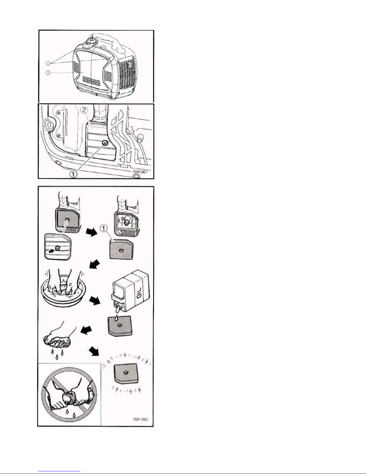
5.4 Air Filter Maintenance should be
performed every 6 months or 100 hours. The
air filter may need to be cleaned more
frequently when using in unusually wet or
dusty areas.
1.
Remove the screws ① and then
remove the cover ②.
2.
Remove the screws ① and then
remove the air filter case cover ②.
3.
Remove the foam element ①.
4.
Wash the foam element in
solvent and dry it.
5.
Oil the foam element and
squeeze out excess oil. The
foam element should be wet but
not dripping.
NOTE: Do not wring out the foam element
when squeezing it. This could cause it to
tear.
6.
Insert the foam element into the
air filter case. Be sure the foam
element sealing surface matches
the air filter so there is no air leak.
NOTE: The engine should never run
without the foam element.
7.
Install air filter case cover,
cover, and screws.

5-5
5.5 Muffler Screen and Spark
Arrestor Maintenance
Should be performed every 6 months or
100 hours. The air filter may need to be
cleaned more frequently when using in
unusually wet or dusty areas.
1.
Remove the screws ① and
then remove the cover ②.
2.
Loosen the bolt ① and the
remove the muffler cap ②, the
muffler screen ③ and spark
arrester ④
3.
Remove the carbon deposits on
the muffler screen and spark
arrester using a wire brush. Use
wire brush lightly to avoid
damaging the muffler screen or
spark arrestor.
4.
Check the muffler screen and
spark arrester replace them if
damaged.
5.
Install the spark arrester.
6.
Install the muffler cap.
7.
Install the cover and tighten the
screws.

5-6
5.6 Fuel Filter Maintenance
Should be performed every 12 months or
300 hours.
1.
Remove the fuel tank cap and filter
①.
2.
Clean the filter with gasoline.
3.
If damaged, replace it.
4.
Wipe the filter and install it.
5.
Install the fuel tank cap.
WARNING!
GASOLINE IS FLAMMABLE. DO
NOT perform this maintenance while
smoking or near an open flame.

6-1
SECTION 6:
Storage
6.1 Long Term Storage
Long term storage of your machine will
require some preventive procedures to
guard against deterioration.
Drain the fuel
1.
Turn the Engine switch to
“OFF” ①.
2.
Remove the fuel tank cap.
Extract the fuel tank into an
approved gasoline container using
a commercially available hand
siphon. Then, install the fuel tank
cap.
WARNING!
GASOLINE IS FLAMMABLE. DO NOT
perform this maintenance while
smoking or near an open flame.
Immediately wipe off spilled fuel
with a clean, dry, soft cloth, since
fuel may deteriorate painted
surfaces or plastic parts.
3.
Turn the Engine switch to “ON”.
4.
Turn the fuel tank cap air vent knob
and Fuel Tap knob to “ON” ①.
5.
Start the engine and let it run until it
stops. Duration of the running
engine depends on the amount of
the fuel left in the tank.

6-2
6.
Remove the screws ①, and
then remove the cover ②.
7.
Drain the fuel from the carburettor
by loosening the drain screw ③ on
the carburettor float chamber.
8.
Turn the Engine switch to
“OFF”
9.
Turn the fuel cock knob to
“OFF”
10.
Tighten the drain screw
11.
Install the cover and tighten the
screws.
12.
Turn the fuel tank cap air vent
knob to “OFF”
13.
Store the generator in a dry, wellventilated place, with the cover
placed over it.
Engine
Perform the following steps to protect the cylinder, piston ring, etc. from
corrosion.
1.
Remove the spark plug, pour about one table-spoon of SAE 10W-30
or 20W-40 motor oil into the spark plug hole and reinstall the speak
plug. Recoil start the engine by turning over several times (with
ignition off) to coat the cylinder walls with oil.
2.
Pull the recoil starter until you feel compression. Then stop
pulling (this prevents the cylinder and valves from rusting).
3.
Clean exterior of the generator and apply a rust inhibitor.
4.
Store the generator in a dry, well-ventilated place, with the cover
placed over it.
5.
The generator must remain in a vertical position when stored,
carried, or operated

7-1
SECTION 7:
Troubleshooting and Specifications
7.1 Troubleshooting Diagram
Does

7-4
7.2 Fuel Filter Maintenance
Use this section to troubleshoot common errors.
Engine won’t start
Fuel systems: No fuel supplied to combustion chamber
•
No fuel in tank…….supply fuel.
•
Fuel in tank……..Fuel tank cap air vent knob and fuel cock knob to “ON”.
•
Clogged fuel line…….clean fuel line.
•
Clogged carburettor….clean carburettor.
Engine oil system insufficient
•
Oil level is low….add engine oil.
Electrical systems
•
Engine switch to “ON” and pull the recoil starter. Poor spark
•
Spark plug dirty with carbon or wet…Remove carbon or wipe spark plug dry.
•
Faulty ignition system….Consult a service centre.
Generator won’t produce power
•
Safety device (DC protector) to ”OFF” ….press the DC protector to “ON”
•
Safety device (AC) to “OFF”….stop the engine, then restart.
7.3 Specifications
Engine Type
4-Stroke OHV Yamaha MZ80 Air Cooled Single Cylinder
Engine Displacement (cc)
79cc
Running Watts
1600w
Starting Watts
2000w
Rated Frequency
50HZ
Rated Voltage
240V
Rated Current
6.7A
Run Time
10.5hrs at 1/4 load
Receptacles (qty.)
(2) 240V AC; (1) 12V 8A DC
Net Weight
20kg
Noise Level (dB)
51dB @ 1/4 Load
Fuel Type
Unleaded gasoline
Fuel Capacity (litres)
4.2
Oil Type
SAE 10W-30
Start Type
Recoil
Dimensions L x W x H
50cmx28cmx45cm approx.

7-5
Warranty
Whilst every effort is made to ensure your
complete satisfaction with this tool, occasionally,
due to the mass manufacturing techniques, a tool
may not live up to our required level of
performance and you may need the assistance of
our service department.
This product is warranted for a 12 month period
for domestic use and a 3 month period for
commercial use from the date of the original
purchase. If found to be defective in materials or
workmanship, the tool or the offending faulty
component will be replaced free of charge with
another of the same item. A small freight charge
may apply. Proof of purchase is essential.
We reserve the right to reject any claim where the
purchase cannot be verified. This warranty does
not include damage or defects to the tool caused
by or resulting from abuse, accidents, alterations
or commercial or business use. It also does not
cover any bonus items or included accessories.
Only the generator is covered under this
warranty.
Please ensure that you store your receipt in a
safe place. Conditions apply to the above
warranty.
1. DURATION: The manufacturer warrants that it will
repair or replace, at no charge for parts or labour, the
KAWASHIMA Generator, if proven defective in material
or workmanship, during the following time period(s) after
date of original retail purchase:
For 1 Year:
The KAWASHIMA PRO2000i Generator (excluding
accessories)
2. WHO GIVES THIS WARRANTY (Warrantor):
EUROQUIP NZ EUROQUIP AUSTRALIA
Service Line: Service Line:
+ 64 3 547 8409 1 - 800 040 947
3. WHO RECEIVES THIS WARRANTY (Purchaser):
The original purchaser of this KAWASHIMA Generator
4. WHAT IS COVERED UNDER THIS WARRANTY:
Defects in material and workmanship which occur within
the duration of the warranty period.
5. WHAT IS NOT COVERED UNDER THIS
WARRANTY:
A. Implied warranties, including those of merchantability
and FITNESS for a particular purpose are limited in
duration to this express warranty. After this period, all
risks of loss, from whatever reason, shall be on the
purchaser.
B. ANY INCIDENTAL, INDIRECT, OR
CONSEQUENTIAL LOSS, DAMAGE, OR EXPENSE
THAT MAY RESULT FROM ANY DEFECT, FAILURE
OR MALFUNCTION OF THIS PRODUCT.
C. This warranty does not apply to any accessory or
consumable items included with the product which are
subject to wear from usage; the repair or replacement of
these items shall be at the expense of the owner. These
items include, but are not limited to: sparkplugs, seals,
O-rings, recoil starter parts, etc. In addition, this warranty
does not extend to any damage caused by the untimely
replacement or maintenance of any of the previously
listed CONSUMABLE parts.
D. Any failure that results from accident, purchaser’s
abuse, neglect or failure to operate products in
accordance with instructions provided in the owner’s
manual(s) supplied with the product.
E. Pre-delivery service, i.e. assembly and adjustment.
6. RESPONSIBILITIES OF WARRANTOR UNDER
THIS WARRANTY: Repair or replace, at Warrantor’s
option, products or components which have failed within
duration of the warranty period.
7. RESPONSIBILITIES OF PURCHASER UNDER THIS
WARRANTY:
A. Please call your re-seller or the number listed above
for warranty assistance.
B. Provide dated proof of purchase and maintenance
records.
C. All generators must be delivered or shipped to the
nearest Service Agent or re-seller. Freight costs, if any,
must be borne by the purchaser.
D. Use reasonable care in the operation and
maintenance of the products as described in the owner’s
manual(s).
E. No warranty costs incurred will be considered for, or
covered if Euroquip has not been contacted and prior
permission for repair / replacement has been granted.
8. WHEN WARRANTOR WILL PERFORM REPAIR OR
REPLACEMENT UNDER THIS WARRANTY:
Repair or replacement will be scheduled and serviced
according to the normal work flow at the servicing
location and depending on the availability of replacement
parts.
 Loading...