

Kawasaki LSI KE5B256B1CFP Datasheet

Ver. 1.2.1
ADDRESS PROCESSOR
64k-bit • 3-port type
KE5B256B1

Address Processor KE5B256B1
Table of Contents
1. Features
1.1 Introduction
1.2 Functional Overview
1.3 Specifications
1.4 Register Names
2. Block Diagram
3. Pin Assignment and Pin Descriptions
3.1 Pin Assignment
3.2 Pin Descriptions
4. Port and Operation Mode Overview
4.1 Port Overview
4.2 Arbitration
4.3 Operation Modes Overview
4.4 External Arbitration
5. CAM Table
5.1 Entry and Segment
5.2 Table Configuration
5.3 Read/Write Segment Data
5.4 Search and CAM Table
6. Input Port
6.1 Input Port Configuration
6.2 IP Sequence Configuration
6.3 Selection of Channel and Start Sequence Number
6.4 IP Sequence Operation
6.5 HHA Automatic Output
7. Output Port
7.1 OP Sequence Configuration
7.2 Selection of Channel and Start Sequence Number
7.3 OP Sequence Operation
8. CPU Port
8.1 Access to Registers
8.2 Basic Operation through CPU Port
8.3 Search Operation through CPU Port
8.4 Search Result Output from CPU Port
8.5 HHA/HEA Register Operation
8.6 Automatic Increment Function
8.7 Table Maintenance
9. Cascading
9.1 Device ID Registration
9.2 Priority
9.3 Cascade Connection
9.4 Input Port in a Cascade System
9.5 Output Port in a Cascade System
9.6 CPU Port in a Cascade System
9.7 AC Characteristics in a Cascade System
9.8 Single Device Operation
10. Initialization
11. Examples
12. Command Descriptions
12.1 Command Functions
12.2 Conditions for Executing Commands
13. Register Descriptions
13.1 Overview
13.2 Register Addresses
13.3 Register Bit Maps
13.4 Conditions for Accessing Registers
14. Electrical Characteristics
14.1 Absolute Maximum Ratings
14.2 Operating Range
14.3 DC Characteristics
14.4 AC Characteristics
15. Package Outline

1-1
Address Processor KE5B256B1
1. Features
1.1 Introduction
KE5B256B1 is a 256k-bit CAM (Content Addressable
Memory) device with a new architecture. The main function of the LSI is fast searching of data on the search data
table stored in CAM. User can define the row/column table
size flexibility. The width of one entry in the search data
table can be selected from 32 bits to 256 bits, in increments
of 32 bits (1 segment). User can define the area to be
searched in an entry freely in terms of the position and bit
width. The search operation is executed for each segment,
and the cycle time is 80ns with the fast operation characteristic of CAMs. KE5B256B1 provides 3 ports, an Input
Port, Output Port and CPU Port. These ports are designed
to have the most appropriate functionality.
The Input Port, which is only used for inputting the key
data, provides the programmable input data formatter and
programmable sequencer. These capabilities enable the
formatting of the incoming key data and flexible search
operation with any table column as a pre-determined sequence by writing into the Input Port.
Therefore, user can execute complex search operations
quickly. The search results can be output by flag pin and
by register reading from the Output Port or the CPU Port.
The Output Port is only used for outputting the search results. Like the Input Port, it has a programmable sequencer. The Output Port can output search results automatically according to a pre-determined sequence by reading from the Output Port.
The CPU Port is used for the definition of the search table,
the table configuration/maintenance and the configuration
of the Input Port and the Output Port . The CPU Port has
registers and commands by which user can realize functions easily. The registers can be accessed with direct addressing, and there are various effect commands for table
maintenance. The input/output data bus is 16 bits in width.
An endian function is supported to make it easy to access
the search table data of 32 bits. The upper 16 bits or the
lower 16 bits of the segment can be read/written with the
same address using the endian function.
Multiple devices can be easily cascade-connected in order
to increase the number of entries in the CAM table without
external logic. The extended CAM realized by cascade
connection can be treated as if it were one continuous table
in one device, because priority control is done internally
between devices.
However, the number of segments forming one entry in the
search data table must be the same in all devices (even if
the devices are not cascade connected).
This device must arbitrate between ports to protect against
data destruction caused by simultaneous access from plural ports. User can select two methods of arbitration. One
is an internal arbitration mode which restricts the device to
internal operation by port-dependent modes (CPU mode,
IP mode, OP mode, IOP mode). In this case, the device
determines whether the device receives operations from
every port or not. The other is external arbitration. In this
case, simultaneous access from every port is not permitted.
However, user can decrease the execution cycles, because
instead of external arbitration, mode restriction is not applied. User can select either method according to the required applications.

1-2
Address Processor KE5B256B1
1.2 Functional Overview
The KE5B256B1 (Address Processor: AP) provides the
best solution to the fast and complex "Address Filtering"
requirements of today's internetworking equipment with
the following outstanding functions.
(1) Flexible search data table definition answering to various protocols.
• The entry size is configurable from 32 bits to 256
bits.
• The search operation of any width key data can be
performed with data at any position in the table.
• All the CAM area can be accessed as RAM.
(2) 3-port architecture
• Optimized functionality for each port provides
fast data processing.
(3) Programmable input data formatting and search sequence
• The input data width can be selected as 32, 16, or
8 bits.
• Definition of data input and search start position.
• Masking by bit is possible.
• Search window set by byte unit.
• Maximum 8 step search sequence definition
to any column of the table.
(4) Programmable output sequence
• Output sequence definition of any search
result.
• Output sequence definition of any column of
the hit entry.
(5) Multi-channel sequence
• A maximum of 16 kinds of IP sequences and OP
sequences can be defined by indicating the channel/
number of the start sequence.
(6) Cascading
• No additional logic is required.
• A cascaded table acts as one integral search data.
(7) Commands
• Useful commands for the search table maintenance
1.3 Specifications
·
CA M core Capacit
y
256 kbits
Access to table entry Random access to all data
(RAM, CAM substitution)
Configuration Configurable to control the entry width from 32 b its to 256 bits
(Entry size) in units of 32 bits
• 32 bits x 8,192 entries
• 64 bits x 4,096 entries
• 96 bits x 2,728 entries
• 128 bit s x 2,048 en trie s
• 160 bit s x 1,636 en trie s
• 192 bit s x 1,364 en trie s
• 224 bit s x 1,168 en trie s
• 256 bit s x 1,024 en trie s
Cascad in
g
Up to 32 devices (adds table depth
)
Search Operatio n • Via C PU Port
• Via Inp ut Port (automatic)
• Masking by bit
• Search o peratio n by table segmen t (32 bits)
• AN D search f or mo re t ha n 32 bits of data
• H it accumulation using Access Bit
Result Ou tput • Via C PU Port
• Via Output Port (automatic)
• Hit result p in ( H O _)
• I ntermediate search result pins ( SH0_, SH1_)
•Hit
• Hit add ress
• Entry data of hit address
•
Key data use d in se arch o pe ration
1-3
Address Processor KE5B256B1
Specifications (cont'd)
Ports I nput Port · Input data bl ock width is s electable (32, 16, or 8 bits
)
(Key
data input
)
· Multi-channel:
IP sequence of 2 channels (A/B) can be defined.
Numb er of start sequence can be selected.
Input Port sequence Maximum 8-step input sequen ce co nf iguration and data
(
IP Sequence
)
formatting functions.
· Cut Through:
Any block selectable among 64 b locks in d ata stream
· Data Accumulation :
M ost recent 64 bit s can be temporarily stored
(Accu mulat io n Buf fer & Sub-accu mulation Buff er
)
· Search Window Set:
Key data selectable w ith 32-bit width among 64 b its of
accumulated data starting from n (n=0-3, n byte shift) byte
· Mask operation by bit
· Any segm en t can be searched in any order.
Output Port · 32 bits
(
Search result output
)
· Multi-channel
OP sequence of 2 channels (A/B) can be defined.
Numb er of start sequence can be selected.
Output Port sequence Maximum 8-step output sequen ce co nf iguratio n
(
OP Sequence
)
· Search key data:
Key data a fter d ata fo rmatting used in the IP sequence
(CMP0 - CMP7 register
)
· Hit status:
Hit, m u lt i- hit, used cha n nel (HSTAT register
)
· Hit address:
Hit entry add ress w ith the highest priority (HHA register
)
· Contents of hit add ress (MEMHHA register
)
* Hit status can be output in combin a t io n with ot her search results
CPU Port · 16-bit data, 8-bit addres s
· C o mm a n d ex ecut ion
· Regist er Rea d/Write
Sequence · SQRST_ (Pin
)
reset · SSQRST command (from CPU Port
)
Search resu lt · HO_: Result s of ea ch search operat io n
output pins · SH0_, SH1_: Interm edia t e search results of specified step in the IP sequence
Cycle time 80ns
I/F LVTTL compatible
Supply voltage 3.3V ± 0.3V
Package144-
p
in PQFP
T ech no lo
gy
0.5µ m CMOS

1-4
Address Processor KE5B256B1
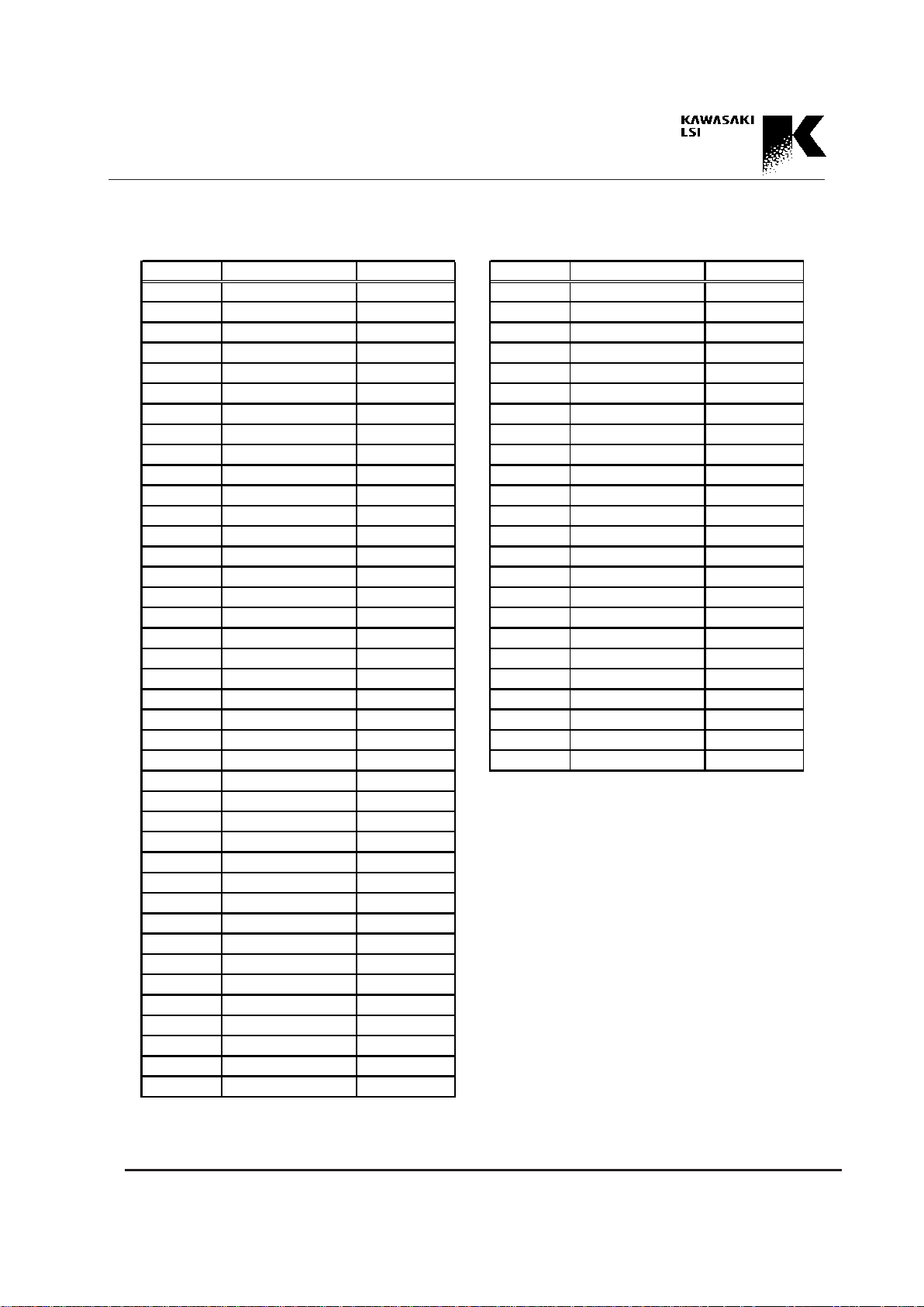
1.4 Register Names
Register names are described by the following abbreviations.
Abbreviations of Registers
Abbreviation Register Name
COM Register Command Register
CNTL Register Control Register
DEVID Register Device ID Register
DEVSTAT Register Device Status Register
DEVSEL Register Device Select Register
AR Register Address Register
MEMAR Register Memory_AR Register
MEMHHA Register Memory_HHA Register
MEMHEA Register Memory_HEA Register
CPUHS Register CPU HHA/HEA Segment Register
MEMAR_AT Register Memory_AR Attribute Register
MEMHHA_AT Register Memory_HHA Attribute Register
MEMHEA_AT Register Memory_HEA Attribute Register
SHASGN Register Sequence Hit Flag Assignment Register
HHASGN Register HHA Automatic Output Assignment Register
CUT Register Cut Register
SS Register Search Start Register
CS Register Channel Sequence Register
MASK Register Mask Register
AOC Register Automatic Output Control Register
AOSC Register Automatic Output Sub Control Register
CPUINP Register CPU Input Data Register
CPUMASK Register CPU Mask Register
CPUSRS Register CPU Search Segment Register
CPUINP2 Register CPU Input Data 2 Register
CPUMASK2 Register CPU Mask 2 Register
CPUSRS2 Register CPU Search Segment 2 Register
HSTAT Register Hit Status Register
ESTAT Register Empty Status Register
HHA Register Highest Hit Address Register
HEA Register Highest Empty Address Register
SH Register Sequence Hit Result Register
CMP Register Comparand Register
2-1
Address Processor KE5B256B1
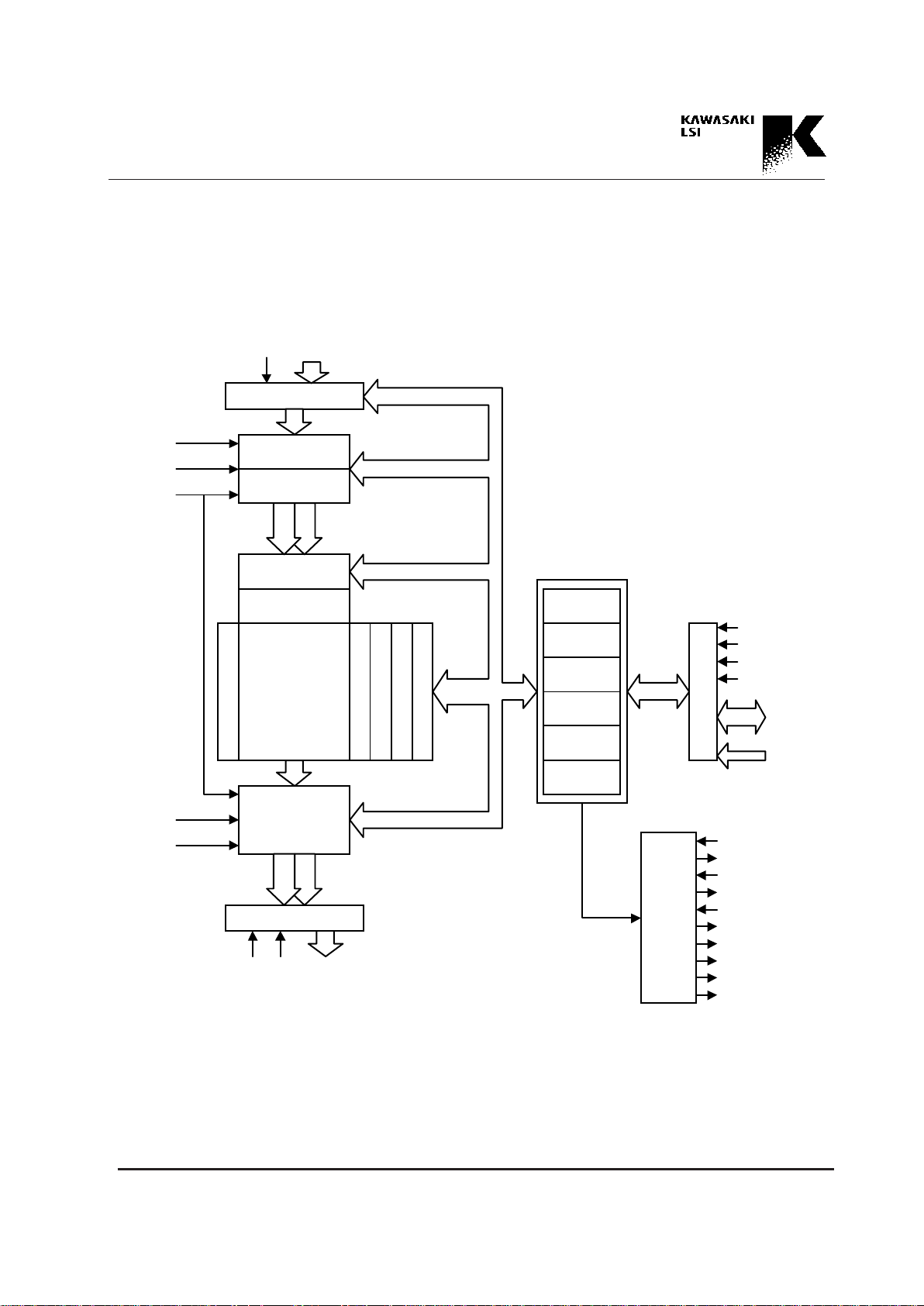
Fig. 2-1 Block Diagram
2. Block Diagram
OD<31:0>
Input Port (8, 16, 32 bits)
WR
ID<31:0>
Data Formatter
Input Port Sequencer
IPCH
ISNM<2:0>
SQRST_
32 bits
MASK 0 - 7
Comparison Logic
CAM Array
8,192 words 32bits
Decoder
Empty Bit
Hit Flag
Access Bit
Priority Encoder
32 bits
Output Port Sequencer
OPCH
OPNS
A ch
B ch
A ch
B ch
32 bits
Output Port
OE_
RD_
32 bits
Command
Control Status
Memory R/W
Configuration
CPU Search
Table Status
16 bits
CPU Port
16 bits
CE_
R/W_
RST_
SP/TP_
DAT<15:0>
ADD<7:0>
8 bits
Flag Logic
FLI_
FLO_
PI_
PO_
HI_
HO_
SH0_
SH1_
IPBUSY_/OPACT_
OPBUSY_/IPACT_
16 bits
3-1
Address Processor KE5B256B1
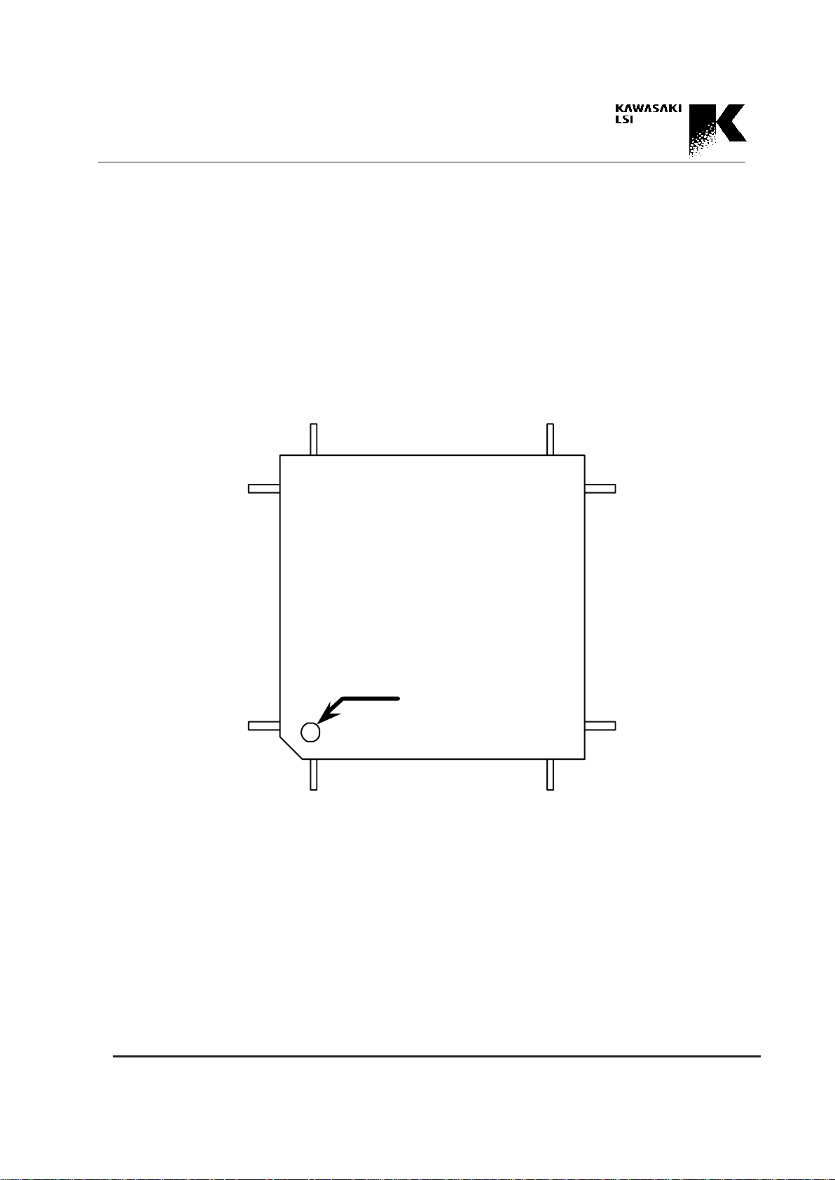
Fig. 3.1.1 Pin Assignment
KE5B256B1CFP
(144-pin PQFP type)
3. Pin Assignment and Pin Descriptions
3.1 Pin Assignment
36
37
1
144
109
73
72
108
index
KE5B256B1CFP
QFP144
•
•
•
•
•
•
•
•
•
•
••••
••••
3-2
Address Processor KE5B256B1
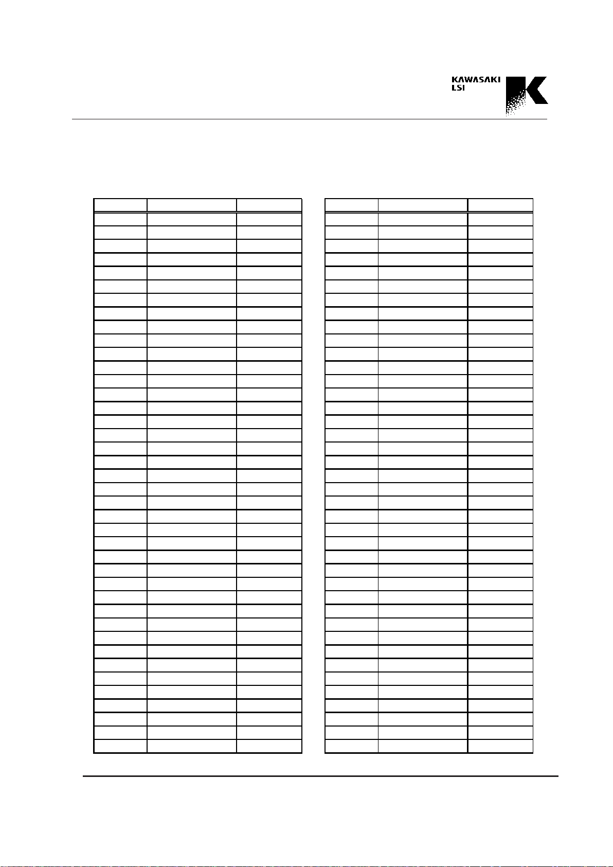
Table 3.1 Pin Assignment
Pin No. Signal Name I/O type Pin No. Signal Name I/O type
1 V DD - 41 ID<22> IN
2 OD<2> OUT 42 ID<23> IN
3 OD<1> OUT 43 ID<24> IN
4 OD<0> OUT 44 ID<25> IN
5 OE _ IN 45 ID<2 6> IN
6 PO _ OUT 46 ID<2 7> IN
7 PI_ IN 47 ID<28> IN
8 SH1_ OUT 48 ID<29> IN
9 SH0_ OUT 49 ID<30> IN
10 HO_ OUT 50 ID<31> IN
11 HI_ IN 51 IPBUSY _/OPACT_ OUT
12 FLO_ OU T 52 OPB US Y_/IPACT_ OUT
13 VDD - 53 WR IN
14 ID<0> IN 54 G ND 15 ID<1> IN 55 G ND 16 ID<2> IN 56 G ND 17 GND - 57 SQRST_ IN
18 GND - 58 RST_ IN
19 GND - 59 RD_ IN
20 ID<3> IN 60 ADD<0> IN
21 ID<4> IN 61 ADD<1> IN
22 ID<5> IN 62 ADD<2> IN
23 ID<6> IN 63 ADD<3> IN
24 ID<7> IN 64 ADD<4> IN
25 ID<8> IN 65 ADD<5> IN
26 ID<9> IN 66 ADD<6> IN
27 ID<10> IN 67 ADD<7> IN
28 ID<11> IN 68 G ND 29 ID<12> IN 69 R/W_ IN
30 ID<13> IN 70 CE_ IN
31 ID<14> IN 71 NC OPEN*1
32 ID<15> IN 72 V DD 33 ID<16> IN 73 V DD 34 ID<17> IN 74 DAT<0> IO
35 ID<18> IN 75 DAT<1> IO
36 VDD - 76 DAT<2> IO
37 VDD - 77 DAT<3> IO
38 ID<19> IN 78 DAT<4> IO
39 ID<20> IN 79 DAT<5> IO
40 ID<21> IN 80 G ND -
3-3
Address Processor KE5B256B1
*1 NC pins should be open. (Do not connect.)
Table 3.1 Pin Assignment (cont'd)
Pin No. Signal Name I/O type Pin No. Signal Name I/O type
81 VDD - 121 OD<19> OUT
82 DAT<6> IO 122 OD<18> OUT
83 DAT<7> IO 123 OD<17> OUT
84 DAT<8> IO 124 OD<16> OUT
85 DAT<9> IO 125 GND 86 DAT<10> IO 126 GND 87 DAT<11> IO 127 GND 88 DAT<12> IO 128 OD<15> OUT
89 DAT<13> IO 129 OD<14> OUT
90 GND - 130 OD<13> OUT
91 GND - 131 OD<12> OUT
92 GND - 132 V DD 93 DAT<14> IO 133 OD<11> OUT
94 DAT<15> IO 134 OD<10> OUT
95 ISNM<0> IN 135 OD<9> OUT
96 ISNM<1> IN 136 OD<8> OUT
97 ISNM<2> IN 137 GND 98 OPNS IN 138 OD<7> OUT
99 IPCH IN 139 OD<6> OUT
100 OPCH IN 140 OD<5> OUT
101 G ND - 141 OD<4> OUT
102 OD<31> OUT 142 OD<3> OUT
103 OD<30> OUT 143 NC OPEN*1
104 OD<29> OUT 144 V DD 10 5 SP/TP_ IN
106 NC OPEN *1
107 FL I_ IN
108 V DD 109 V DD 110 OD<28> OUT
111 OD<27> OUT
112 OD<26> OUT
113 OD<25> OUT
114 OD<24> OUT
115 G ND 116 OD<23> OUT
117 OD<22> OUT
118 OD<21> OUT
119 OD<20> OUT
120 V DD -

3-4
Address Processor KE5B256B1
Function
DAT<15:0>
ADD<7:0>
CE_
R/W_
RST_
ID<31:0>
3.2 Pin Descriptions
Pin name Attribute
CPU Port Data Bus
Input / Output
Tri-state LVTTL
CPU Port Address
Bus
Input
LVTTL
Device Enable
Input
LVTTL
Read/Write
Input
LVTTL
Hardware Reset
Input
LVTTL
Input Port
Data Bus
Input
LVTTL
DAT<15:0> is a 16-bit, bidirectional data bus used to convey data, commands, and status to and from the Address
Processor (AP). The direction is controlled by the state of
R/W_. DAT<15:0> is enabled by a low level of CE_.
ADD<7:0> is an 8-bit address bus used to select registers.
CE_ is used for access from the CPU Port. R/W_,
ADD, DAT inputs are latched on the falling edge of CE_.
R/W_ low selects a write cycle. R/W_ high selects a read
cycle. The state of R/W_ is registered on the falling edge of
CE_.
RST_ is a hardware reset signal. A low pulse of RST_ initializes the AP. The minimum low hold time is 40ns.
ID<31:0> is a 32-bit data bus used to convey search data to
the AP through the Input Port. The ID bus width can also
be configured to 8 bits (ID<7:0>) or 16 bits (ID<15:0>).

3-5
Address Processor KE5B256B1
FunctionPin Name Attribute
Input Port
Write Pulse
Input
LVTTL
Port Number
Select
Input
LVTTL
Input/Output
Port Sequence
Pointer Reset
Input
LVTTL
Output Port
Data Bus
Output
LVTTL
Output Port
Read Pulse
Input
LVTTL
Output Port
Outpt Enable
Input
LVTTL
WR
SP/TP_
SQRST_
OD<31:0>
RD_
OE_
WR controls the search operation through the Input Port.
Users can select the polarity of WR.
According to the cut through configuration, data on the ID
bus is transferred on the falling edge (negative pulse) or
the rising edge (positive pulse) of WR.
SP/TP_ controls the mode restriction for register access
and command execution. When the SP/TP_ is pulled
down, the use of independent triple ports and restricts
some operations in the CPU mode. When the SP/TP_ is
pulled up, the use of like a single port and reduces the restriction.
SQRST_ is a Sequence Pointer Reset signal for the Input
Port and Output Port. A low pulse of SQRST_ initializes
the Input Port Sequence Pointer and Output Port Sequence
Pointer. Low hold time requires more than 40ns.
OD<31:0> is a 32-bit data bus used to output the results of
a search operation.
RD_ controls the read access through the Output Port. The
Output Port read cycle starts on the falling edge of RD_.
The OD bus outputs the results of the search operation according to the output sequence configuration.
OE_ enables the OD output. When OE_ is low, the OD
output drivers are enabled. When OE_ is high, OD bus impedance becomes high.

3-6
Address Processor KE5B256B1
FunctionPin Name Attribute
Input Port Busy/
Output Port Active
Output
LVTTL
Output Port Busy/
Input Port Active
Output
LVTTL
Hit Flag Output
Output
LVTTL
Hit Flag Input
Input
LVTTL
IPBUSY_/OPACT_
OPBUSY_/IPACT_
HO_
HI_
IPBUSY_/OPACT_ is used to monitor the status of port
operation. When the SP/TP_ pin is pulled down, this pin
becomes a busy signal for the Input Port. This pin is low
during the Output Port read cycle or CPU mode. On the
other hand, when the SP/TP_ pin is pulled up, this pin becomes an active signal for the Output Port. This pin is low
during the Output Port read cycle.
OPBUSY_/IPACT_ is used to monitor the status of port
operation. When the SP/TP_ pin is pulled down, this pin
becomes a busy signal of the Output Port. This pin is low
during the Input Port read cycle or CPU mode. On the
other hand, when the SP/TP_ pin is pulled up, this pin becomes an active signal for the Input Port. This pin is low
during the Input Port write cycle.
HO_ is used to output search results. This pin is low when
even one hit occurs in the search operation.
This pin is high when no entry is hit. In a cascaded system,
the hit signal of the cascade configuration appear the HO_
output of the lowest priority device (Last Device).
HI_ is used in the cascaded system. HI_ input is connected
to the HO_ output of the adjacent higher priority device.
This connection propagates hit information from a high
priority device to a lower priority device. The HI_ pin of
the highest priority device should be pulled up in a cascaded system, and in a single system, the HI_ pin of the
device should be pulled up.

3-7
Address Processor KE5B256B1
FunctionPin Name Attribute
SH0_, SH1_
PO_
PI_
FLO_
Sequence Hit Flag
Output
Open Drain
Priority Output
Output
LVTTL
Priority Input
Input
LVTTL
Full Flag Output
Output
LVTTL
SH0_ and SH1_ are used to output the intermediate search
results in a search sequence from the Input Port. When there
are search results of a specified sequence number, this pin is
low. On the other hand, when there is no hit, this pin has
high impedance. SH0_ and SH1_ are programmably selected and output intermediate search results.
PO_ is used to propagate priority information of the device
and to output multi-hit information. In a cascaded system,
this pin propagates priority information (DEVID priority)
of cascaded system to the lower priority device.
This pin is also used as a multi-hit status flag. When this pin
is low, multi-hit occurs. In a cascaded system, the PO_
pin of the lowest priority device (Last Device) outputs system multi-hit information.
PI_ is used in a cascaded system. The PI_ input is connected to the PO_ output of the adjacent higher priority device. This connection propagates DEVID priority from a
high priority device to a lower priority device. Multi-hit information is also propagated by this connection. The PI_
pin of the highest priority device should be pulled up in a
cascaded system, and in a single system, the PI_ pin of the
device should be pulled up.
FLO_ is used to output search results. This pin is low when
all entries in the CAM are filled with effective entries (full
status) and there is no entry for new registration.
In a cascaded system, the full signal of the cascade configuration appears at the FLO_ output of the lowest priority device (Last Device).

3-8
Address Processor KE5B256B1
FunctionPin Name Attribute
FLI_
IPCH
ISNM<2:0>
OPCH
Full Flag Input
Input
LVTTL
Input Port
Channel
Input
LVTTL
Input Port
Start Sequence
Number Select
Input
LVTTL
Output Port
Channel
Input
LVTTL
FLI_ is used in a cascaded system. The FLI_ input is connected to the FLO_ output of the adjacent higher priority
device. This connection propagates full/empty information
from a high priority device to a lower priority device. The
FLI_ pin of the highest priority device should be pulled up
in a cascaded system, and in a single system, the HI_ pin of
the device should be pulled up.
IPCH determines the Input Port active channel when hardware channel selection is defined in the CNTL register.
The state of IPCH is registered on the falling edge of the
SQRST_ pulse or CE_ pulse of the SSQRST command.
IPCH low selects channel "A" and high selects channel
"B."
ISNM<2:0> is used to indicate the start search sequence
number.
When a hardware channel selection is defined in the CNTL
register, this 3-bit field indicates the start IP sequence
number directly. Signals on this fields are latched on the
falling edge of the SQRST_ pulse or CE_ pulse of the
SSQRST command.
OPCH determines the Output Port active channel when
hardware channel selection is defined in the CNTL register. The state of OPCH is registered on the falling edge of
the SQRST_ pulse or CE_ pulse of the SSQRST command. IPCH low selects channel "A" and high selects
channel "B."

3-9
Address Processor KE5B256B1
FunctionPin Name Attribute
Output Port
Start Sequence
Number Selection
Input
LVTTL
Supply
Supply
OPNS
VDD
GND
OPNS is used to indicate the start output sequence number.
This pin determines whether the OP start sequence number
is "0" or a number indicated in the CNTL register. A Signal
on the OPNS pin is latched on the falling edge of SQRST_
pulse or CE_ pulse of the SSQRST command. When this
pin is low, the sequence number "0" is selected. On the
other hand, when this pin is high, the sequence number
pointed in the CNTL register is selected.
Power Supply: 3.3V ± 0.3V
Ground

4-1
Address Processor KE5B256B1
4. Port and Operation Mode Overview
4.1 Port Overview
KE5B256B1 has an Input Port, which is only used to input
search key data, an Output Port, which is only used to output search results, and a CPU Port, which is used to control
the device, for table configuration, and for table maintenance. An overview of each port is presented below.
Input Port
The 32-bit Input Port receives data for search operations. The port width is 32-bit in width, but it can be
configured to 16 or 8 bits. When 16 or 8 bits are
configured, 16 or 8 bits on the LSB side of ID<31:0>
are used, with 16 bits, ID<15:0> is effective. With 8 bits,
ID<7:0> is effective. The data on the ID<31:0> is input
into the device by applying a writing pulse (WR pulse) to
the WR pin. A pre-defined search sequence (IP sequence)
then executes. The polarity of the WR pulse is programmable, and can be configured by the user to a negative or
positive pulse. The WR pulse cycle is called the Input
Port cycle.
A sequencer in the Input Port operates synchronously with
the WR pulse. The sequence executes the following processes.
(1) Cut Through
Only desired data blocks as search keys are picked up from
among the input data stream applied from the Input Port.
(2) Data Accumulation
The data blocks picked up in the Cut Through process are
stored in an Accumulation Buffer and a Sub-accumulation
Buffer in the device. The total number of bits which can be
stored in the Accumulation Buffer and Sub-accumulation
Buffer is 64 bits.
(3) Search Window Setting
A 32-bit data block is selected as the search key data from
among the 64-bit data block stored in the above two buffers. The position of the window can be set by byte.
(4) Mask Operation
The 32 bits of search key data selected can be masked by
bit. Masked bits are not compared with the corresponding
bits of the search key data.
(5) Selection of Search Segments
A column position (segment) in the search data table to be
searched is selected.
(6) Execution of Search
These sequencer operation (IP sequence) is programmable.
Each step of the search operation can be defined independently. Two sets of the IP sequence can be defined (2-channel architecture). Each channel can contain a maximum of 8
steps. Two kinds of sequences can execute by changing
these channels. Furthermore, user can use the sequencer
dividing function. In this case, a maximum of 16 kinds in an
IP sequence, which have various search mask definitions
and search segment definitions, can be defined (multi-channel). See Chapter 6 for a detailed discussion of IP sequence
definitions.
Output Port
The 32-bit Output Port provides search results. The data is
output synchronously with an RD_ pulse on the
OD<31:0>. The cycle of the RD_ pulse is called the Output Port Cycle. There are several search results output
from the Output Port as listed below.

4-2
Address Processor KE5B256B1
• Hit status (Hit, Multi-hit, etc.)
• Address of the hit entry
• Stored data of the hit entry
• Key data used in the IP sequence
Users can define which of the results are output and the
numbers of which the results are output in the sequencer
(OP sequence).
The OP sequence is also constructed of two channels, and
each channel can contain a maximum of 8 steps (as in the
IP sequence). Users can use the sequencer dividing function and define multi-channel sequences. See Chapter 7 for
a detailed discussion of IP sequence definitions.
CPU Port
The CPU Port has a 16-bit data bus DAT<15:0> interfacing with the host processor. The address ADD<7:0>
determines which register is accessed in the device. Each
operation through the CPU Port is executed synchronously with a CE_ low pulse. The CE_ pulse cycle is
called the CPU Port Cycle. An R/W_ signal determines
whether a cycle is a reading cycle or a writing cycle.
All operations using the CPU Port are executed by reading
or writing registers indicated by the Address Bus
(ADD<7:0>). The processes executed by the CPU Port are
presented below.
(1) Setting of Basic Device Operations
This setting is executed by writing the CNTL register. The
contents of the setting are an Endian function (see Chapter
5) polarity of the WR pulse and a method of IP/OP channel
selection (see Chapters 6, 7). A detailed discussion of the
bit map of the CNTL register is presented in Section 13.3.
(2) Device ID Registration
(only for cascaded systems)
With a cascaded system, the Device ID must be registered.
A detailed discussion of Device ID registration is presented
in Section 9.1.
(3) CAM Table Configuration
The column size (entry width) and row size (entry number)
of the CAM table must be defined. This definition is called a
table configuration. See Chapter 5 for a detailed discussion.
(4) IP/OP Sequence Definition
The search sequence of the Input Port (IP sequence) and
the output sequence of the Output Port are defined. A
method of input data formatting, mask operation, and the
search segment can defined by setting the Cut register, SS
register, CS register, and MASK register for the IP sequence. See Section 6.2 for a detailed discussion.
A pointing the search required results (Status, Address,
Data) and output segment can defined by setting the AOC
register and AOSC register. A detailed discussion is presented in Section 7.1.
(5) CAM Table Creation and Maintenance
The creation and maintenance of the CAM table are executed by accessing data in the CAM. This operation can be
executed by both the former operation and also by using a
maintenance command. See Chapter 8 for a detailed discussion.
(6) Command Execution
Commands can be executed by writing an OP-code into the
COM register. Some commands are prepared for mode
change, device reset, IP/OP sequence reset, and table maintenance.

4-3
Address Processor KE5B256B1
(7) Search Operation
A search operation may be also executed through the
CPU Port. However, automatic search operations cannot
be defined in search operations through the CPU Port, (as
with the IP sequence). The key data, mask data, or search
segment number should be set up in the CPUINP,
CPUMASK, or CPUSRS register prior to performing
the SRCH command. A detailed discussion is presented
in Chapter 8.
(8) Search Results
The results of the search operation can be output via the
CPU Port by reading the registers (e.g. HSTAT,
ESTAT, HHA, SH, and CMP) which store the hit status,
hit address, and intermediate hit information of the IP sequence. Stored data of the hit entry can be output by reading the MEMHHA register. For a detailed discussion, See
Chapter 8.
In access to the CAM table of above-mentioned operations
(3, 5, 7, and part of 6, 8), simultaneous access through the
Input Port and Output Port is not permitted to protect the
CAM table data against destruction. However, register access except for the CAM table and execution commands
with no relation to CAM table manipulation can be executed while the Input Port and Output Port are running,
because is access will not cause CAM table destruction. A
detailed discussion of operations which are not permitted
simultaneously is presented in Table 4.3.1.
4.2 Arbitration
This device is not permitted to access through plural ports
simultaneously to protect against the CAM data destruction. Therefore, it is necessary to arbitrate operations
through the three ports (CPU, Input, Output) using one of
the two methods described below.
(1) Internal Arbitration
Internal arbitration restricts access simultaneous to the device through plural ports according to the operation mode.
The operation modes in internal arbitration include the
CPU mode, in which a host processor mainly operates , the
IP mode, in which the IP sequence is executed, the OP
mode, in which the OP sequence is executed, and the IOP
mode, which is a waiting mode for shifting to the IP or OP
mode. An TC sub-mode for table definition and a DEVID
sub-mode for Device ID registration are also included.
In internal arbitration, for example, in the CPU mode, the
device is controlled so as not to execute operations through
the Input Port (IP sequence) and the Output Port (OP sequence). Therefore, a shift mode operation is necessary before executing the required operations.
(2) External Arbitration
External arbitration is a method that restricts access simultaneous to the device through plural ports external to the
device. For example, when access signals to each port are
created by the same clock, accesses to each port can be
exclusive. In this case, the command for shifting modes can
be omitted using external arbitration.
There is basically no mode concept in external arbitration.
The only restrictions are on the operation modes that are
related to the TC sub-mode for table definition and a
DEVID sub-mode for Device ID registration.
The SP/TP_ pin determines which arbitration method is selected. When the SP/TP_ pin is pulled down, the internal
arbitration is selected. If pulled up, external arbitration is
selected.

4-4
Address Processor KE5B256B1
4.3 Operation Modes Overview
As mentioned above, during internal arbitration, operation
of the device is restricted by the operation mode. A detailed
discussion of each mode is given below.
CPU Mode
The CPU mode is used to access the device through the
CPU Port. In this mode, accesses through the Input Port
and Output Port become invalid. Transition to the CPU
mode is executed by the device reset operation (applying a
low pulse to the RST_ pin or issuing the SRST command)
or issuing the SWCPUP and SWCPU_IM commands.
Operation through the CPU Port is basically in the CPU
mode, but there are operations which can be executed in the
other modes. In internal arbitration, operations related to
the CAM table can not be executed by shifting to the CPU
mode.
Operations which can be performed only in the CPU mode
are discussed below for the internal arbitration.
• Writing the CNTL Register
The CNTL register is different from the CAM core, but this
register cannot be written in the only CPU mode because
the basic definitions of the CNTL register are important information for accessing to the CAM table. Reading of the
CNTL register can be executed in the other modes.
• Creating the CAM Table and Maintenance
Commands for read/write data of the CAM table can be
executed to protect against data destruction due to simultaneous access through the Input Port and the Output Port
when only the CPU mode can be executed.
• Reading the CMP Register
The CMP register can also be accessed to protect against
data destruction due to simultaneous access through the Input Port and Output Port when only the CPU mode can be
executed.
When you execute the above operation, which can be executed only in the CPU mode, be careful about mode shifting. A summary of the operations which are not permitted
simultaneous access through the Input Port or Output Port
is presented in Table 4.3.1.
DEVID Sub-mode
The DEVID sub-mode, which belongs to the CPU mode,
is used to register a unique Device ID for every cascaded
device. The following operations require to registration of
a Device ID in the DEVID sub-mode.
• STR_DEVID command
• Read/Write to the DEVID register
• NXT_PR command
• END_DEVID command
Do not use the DEVID sub-mode except in Device ID registration. In the case of a single device, the DEVID submode is not necessary to use because Device ID registration is not necessary. See Section 9.1 for a detailed discussion of Device IDÊregistration.
TC Sub-mode
In the TC sub-mode, which belongs to the CPU mode, user
defines how many segments (1 segment = 32 bits) the CAM
table has as one entry. This operation is called table configuration. In the TC sub-mode, only the following operations which are necessary to configure the CAM table are
performed.
• STR_TC command
• Read/Write AR register (pointing the CAM
address)

4-5
Address Processor KE5B256B1
Table 4.3.1 Prohibited operations in simultaneous access through Input Port and Output Port
• Read/Write MEMAR register (Read/Write TC
data)
• END_TC command
These commands cannot be used except in table configuration. Table configuration must be executed when user uses
the device. A detailed discussion of table configuration is
presented in Section 5.2.
IOP Mode
The IOP mode is the stand-by state for the IP mode or OP
mode. The device moves the IOP mode from the CPU
mode when an SWIOP command is executed. In this mode,
the sequencer in the Input Port starts to operate automatically, and the mode of the device moves to the IP mode
(Note 1). When the defined IP sequence ends, the mode
returns to the IOP mode automatically.
When an RD_ pulse is applied in the IOP mode, the sequence in the Output Port starts to operate and the mode of
the device moves to the OP mode. When the defined OP
sequence ends, the mode returns to the IOP mode.
In the IOP mode, operations (e.g. accessing the CAM table
through the CPU Port) which are permitted only in the
CPU mode cannot be executed. When user wishes to execute these operation, it is necessary to change the CPU
mode by issuing an SWCPUP command or SWCPUP_IM
command.
IP Mode
The Input Port is active in the IP mode. When a WR pulse
is applied to the Input Port in the IOP mode, the mode of
the device moves the IP mode and the search operation
starts according to the defined sequence. The search operation is executed synchronously with the WR pulse, and the
Operations Content of operation
Register access to CAM table MEMAR regi ster Read/Write
MEMHHA register Read/Write
MEMHEA register Read/Write
M EM A R _AT register R ea d
MEMHHA_ AT register Read
MEMHEA_AT register Read
Command to CAM table SRCH command GEN_HI T command
SRCH2 command NXT_HE command
PRG_ AL command GEN_FL c ommand
PRG_ NAC command APPEND command
PRG_AC command APPEND_NHE command
RST_AC command RESTORE command
PRG_NACW H c o mmand STMP_AR command
PRG_ACWH command STMP2_AR command
RST_A C WH co mmand ST MP_ HH command
PRG_HH command STMP2_HH command
PRG_AR command STMP_HE command
NXT_H H command STMP2_HE command
Secondary register a ccess to CA M ta ble CN TL register Write
CMP register Read

4-6
Address Processor KE5B256B1
sequence is processed step by step. The IP sequence
pointer increases with each step. When the pointer arrives
at the step which is defined as the end of the sequence, the
pointer stops and the mode returns to the IOP mode automatically. However, when the mode returns to the IOP
mode, the IP sequence will not operate even when a WR
pulse is input, because the sequence pointer is stopped. If
user wishes to start the IP sequence again, it is necessary to
initialize the stopped pointer. Inputting an SQRST_ low
pulse or issuing an SSQRST command initializes the
pointer.
In the IP mode, an output operation through the Output
Port and the operations (e.g. accessing the CAM table
through the CPU Port) which are permitted only in the
CPU mode cannot be executed.
When interrupt commands (SWCPUP, CWCPUP_IM,
SWCPUP_SQE command) are executed before the end of
the IP sequence, the device moves the CPU mode according to the timing of the command specification. A detailed
discussion of interrupt commands through the CPU Port is
presented in a later section.
OP Mode
The Output Port is active in the OP mode. When an RD_
pulse is applied to the Output Port in the IOP mode, the
mode of the device moves to the OP mode and the output
operation starts according to the defined sequence. The
output operation is executed synchronously with the RD_
pulse and the sequence is processed step by step. The OP
sequence pointer with each step. When the pointer arrives
at the step which is defined as the end of the sequence, the
pointer stops and the mode returns to the IOP mode automatically. When the mode returns to the IOP mode, the OP
sequence will not operate when an RD_ pulse is input, because the sequence pointer is stopped. Users who wish to
restart the OP sequence should initialize the stopped
pointer using the sequence pointer reset operation.
In the OP mode, the search operation through the Input
Port and the operations (e.g. accessing the CAM table
through the CPU Port) which are permitted only in the
CPU mode cannot be executed. When the interrupt commands are executed before the end of the IP sequence, the
device moves the CPU mode according to the timing of the
command specification.
(Note 1) The sequence pointer reset operation with changing to the IOP operation is necessary to start the sequence.

4-7
Address Processor KE5B256B1
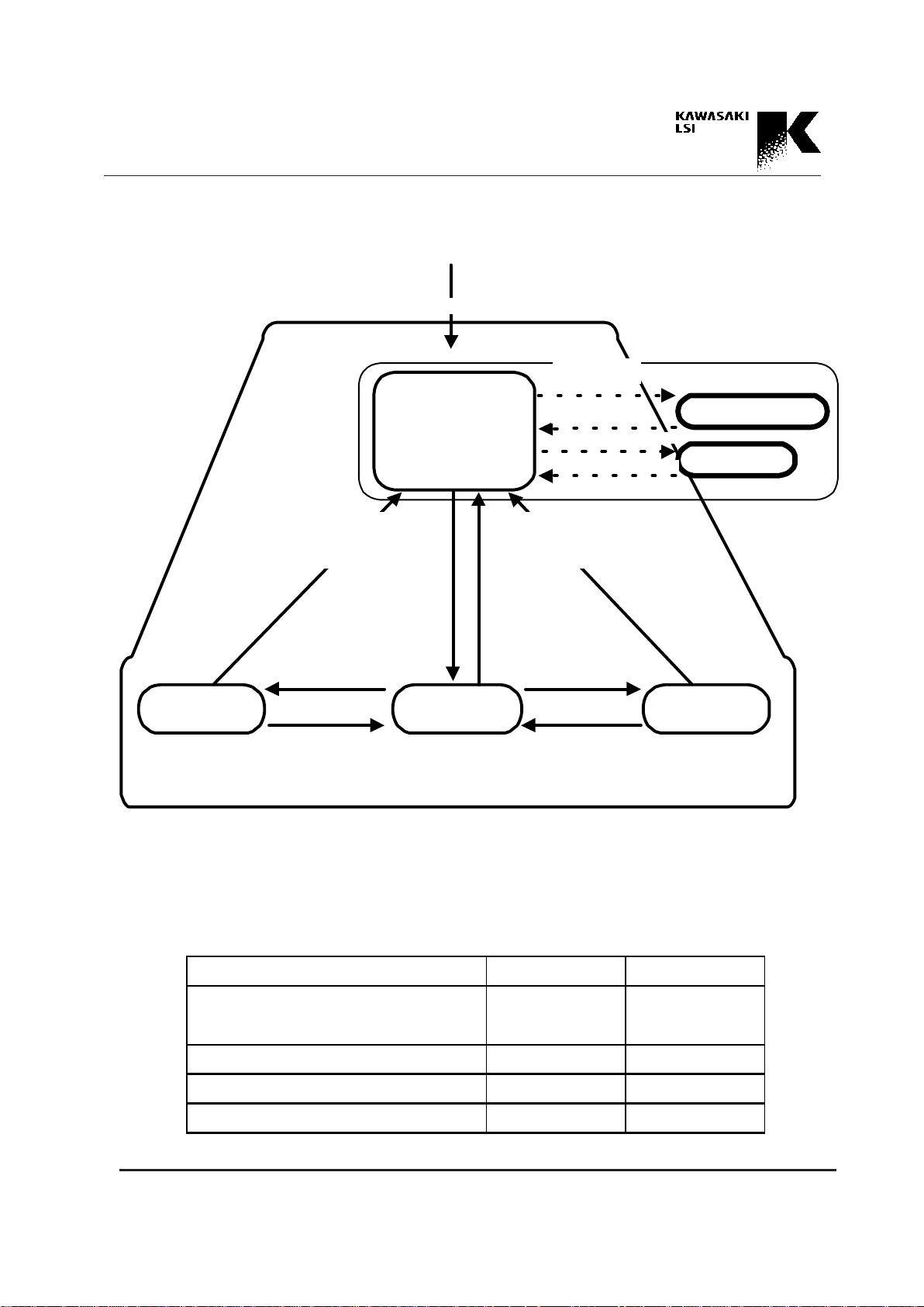
Mode Transition and Command
Mode transition is shown in Fig. 4.3.1 when the SP/TP_ pin
is pulled down (in internal arbitration). The mode transition
is controlled by the WR, RD_ pulses or command. A detailed discussion is presented below.
CPU mode => IOP mode
The transition of the IOP mode from the CPU mode is executed basically by executing the SWIOP command. Some
of the commands which are executed in the CPU mode
have the SWIOP command function. After these commands execute, the device can return to the IOP mode immediately. This function is called the automatic SWIOP
function. Users can determine whether to use the automatic
SWIOP function or not by setting the CPUHS register.
This function omits issuing of the SWIOP command, and
can make processes more efficient. The following 8 commands have the automatic SWIOP function. See Chapters 8
and 12 for a detailed discussion of each command.
• Append commands
APPEND command
APPEND_NHE command
• Stamp commands
STMP_AR command
STMP_HH command
STMP_HE command
STMP2_AR command
STMP2_HH command
STMP2_HE command
IOP mode => IP mode
The transition to the IP mode from the IOP mode is executed by inputting a WR pulse. However, when the sequence pointer stops, the WR pulse is not received and the
mode transition is not executed. If user wishes to move the
IP mode (starting IP sequence), the sequence pointer reset
operation must be executed beforehand. The sequence
pointer reset operation can be executed before the SWIOP
command.
IP mode => IOP mode
When a predefined IP sequence ends, the mode of the device returns to the IOP mode. When the sequence pointer
reset operation is executed in the IP mode, the mode returns to the IOP mode without waiting for the end of the IP
sequence. Users who wish to have the mode return to the
IOP mode in the middle of an IP sequence should use, the
sequence pointer reset operation. (See Chapter 14.)
IOP mode => OP mode
The transition to the OP mode from the IOP mode is executed by inputting an RD_ pulse. However, when the sequence pointer stops, the RD_ pulse is not received and the
mode transition is not executed. If user wishes to move the
OP mode (starting OP sequence), the sequence pointer reset operation must be executed beforehand. The sequence
pointer reset operation for the OP sequence is not necessary if the sequence pointer reset operation is executed before the IP sequence which corresponds to the OP sequence, because the sequence pointer reset operation initializes both the IP sequence pointer and the OP sequence
pointer.
OP mode => IOP mode
When a predefined OP sequence ends, the mode returns to
the IOP mode. When the sequence pointer reset operation
is executed in the OP mode, the mode returns to the IOP
mode without waiting for the end of the OP sequence. Users who wish to have the mode return to the IOP mode in
middle of an OP sequence should use, the sequence pointer
reset operation. (See Chapter 14.)
4-8
Address Processor KE5B256B1
* Device reset RST_pulse or SRST command
** Sequence pointer reset SQRST_pulse or SSQRST command
Power ON *SP/TP_
p
ull down
Device Reset
DEVID sub-mode
CPU mode
IOP mode IP modeOP mode
· RD_pulse · WR pulse
Normal operation state
TC sub-mode
· STR_DEVID
command
· END_DEVID
command
· STR_TC command
· END_TC command
· Sequence pointer reset
**
· End of OP sequence
· Sequence pointer reset
**
· End of IP sequence
· End of OP sequence after SWCPUP,
SWCPUP_SQE command execution
· End of OP cycle after SWCPUP_IM
command execution
· SWIOP command
· Stamp, Append command with
automatic SWIOP command
· End of IP sequence after SWCPUP,
SWCPUP_SQE command execution
· End of IP cycle after SWCPUP_IM
command execution
· SWCPUP command
· SWCPUP_IM command
Fig. 4.3.1 State Diagram in internal arbitration
Table 4.3.2 IPBUSY_/OPACT_, OPBUSY_/IPACT_ in internal arbitration
IPBU SY _/OPACT_ OPBUSY _/IPACT_
CPU m o d e L L
(including DEVID sub-mode and TC sub-mode)
IP mode H L
OP mode L H
IOP mode H H

4-9
Address Processor KE5B256B1
IOP mode => CPU mode
The SWCPUP command or SWCPUP_IM command is issued to move the mode to the CPU mode from the IOP
mode.
IP mode/OP mode => CPU mode (CPU interrupt)
When the CPU interrupt commands (SWCOUP,
SWCPU_IM, SWCPUP_SQE) are issued, user can move
the mode to the CPU mode from the IP mode/OP mode
without using the IOP mode. A detailed discussion of CPU
interrupt commands is presented below.
• SWCPUP Command
When a SWCPUP command is issued during an IP sequence/OP sequence, the CPU interrupt is reserved and the
device moves to the CPU mode without passing through
the IOP mode after the end of the sequence being executed.
When a SWCPUP command is issued in the IOP mode, the
device moves to the CPU mode immediately.
• SWCPUP_SQE Command
A SWCPUP_SQE command also moves the mode to the
CPU mode after the end of the IP sequence/OP sequence.
However, when the command is issued in the IOP mode,
the interrupt is only reserved and the device does not move
to the CPU mode immediately. This point is different from
the SWCPUP command. In this case, the transition to the
CPU mode is also executed after the end of the IP sequence/OP sequence.
• SWCPUP_IM Command
When an SWCPUP_IM command is issued during an IP
sequence/OP sequence, the CPU interrupt is reserved immediately and the device moves to the CPU mode without
waiting for the end of sequence being executed. The input
Port cycle/Output Port cycle, which is executed when an
SWCPUP_IM command is issued, continues to operate
and the device moves to the CPU mode at the end of the
cycle. When an SWCPUP_IM command is issued in the
IOP mode, the device moves to the CPU mode immediately.
The IP sequencer/OP sequencer detects the issuance of the
above-mentioned CPU interrupt commands at the edge of
the WR/RD_ pulse. (See Chapter 14, CPU interrupt in the
IP mode/OP mode.) When the timing shown in Chapter 14
is not observed, the command is not detected until the next
edge of the WR/RD pulse, and the transition to the CPU
mode is executed late. The transition to the CPU mode can
be confirmed by the DEVSTAT register or the IPBUSY_/
OPACT_ pin and OPBUSY_/IPACT_ pin.
If there is no WR/RD_ pulse for some reason, the interrupt
command is not detected and the transition to the CPU
mode is not executed. In this case, the SWCPUP command
can move the device to the CPU mode after the IP/OP sequence is stopped by a sequence pointer reset operation.
CPU mode <=> DEVID sub-mode
Normal transition to the DEVID sub-mode from the CPU
mode is executed by issuing an STR_DEVID command.
The END_DEVID command is issued to return to the CPU
mode after Device ID registration.
CPU mode <=> TC sub-mode
Normal transition to the TC sub-mode from the CPU mode
is executed by issuing an STR_TC command. The
END_TC command is issued to return to the CPU mode
after table configuration.
Users can confirm the mode of the device by reading the
DEVSTAT register or the IPBUSY_/OPACT_ pin and
OPBUSY_/IPACT_ pin.
The IPBUSY_/OPACT_ and OPBUSY_/IPACT_ pins be-

4-10
Address Processor KE5B256B1
come busy signals in internal arbitration, as shown in
Table 4.3.2.
Both the IPBUSY_/OPACT_ and OPBUSY_/IPACT_
pins become low and indicate "Busy" to the Input Port/
Output Port in the CPU mode (including the DEVID submode and TC sub-mode).
The OPBUSY_/IPACT_ pin becomes low to prohibit operation through the Output Port and indicates "Busy" of
the Output Port. The IPBUSY_/OPACT_ pin becomes low
to prohibit operation through the Input Port and indicates
"Busy" of the Input Port. The IPBUSY_/OPACT_ and the
OPBUSY_/IPACT_ pins become high to indicate a ready
status to the IP sequence or the OP sequence in the IOP
mode.
The CPF bit of the DEVSTAT register is a flag which indicates that the mode is the CPU mode in internal arbitration.
The IPF bit of the DEVSTAT register is a flag which indicates that the mode is the IP mode in the internal arbitration. The OPF bit of the DEVSTAT register is a flag which
indicates that the mode is the OP mode in the internal arbitration. See Chapter 13 for a detailed discussion of the bit
map of the DEVSTAT register.
Examples of typical use in the internal arbitration are presented below.
When the device reset operation by an RST_ signal (or the
SRST command) is executed, the device moves to the CPU
mode automatically. After Power ON, a device reset operation by a low pulse of the RST_ signal must be executed.
The device reset operation initializes many registers. The
initialized values are shown in Chapter 13. Registers for
the IP sequence/OP sequence have pre-determined initial
values.
Register the Device ID in every device by moving the
DEVID sub-mode after the device reset operation in a cascaded system. After Device ID registration, the transition
back to the CPU mode is executed by an END_DEVID
command. See Chapter 9 for a detailed discussion of Device ID registration.
In the case of a single device, Device ID registration is not
necessary.
First, execute a designation of the device operation by
setting the CNTL register in the CPU mode after the device
reset operation (Device ID registration in a cascaded system). (A detailed discussion of the CNTL register is presented in Chapter 13.)
Second, execute a table configuration by moving to the TC
sub-mode. When the table configuration of all CAM words
ends, the transition back to the CPU mode is executed by
the END_TC command.
Third, execute the create table operation (writing table
data). See Chapter 8 and 12 for a detailed discussion of the
command set for accessing and maintenance of the CAM
table.
Execute IP sequence/OP sequence definition by setting the
CUT register, SS register, CS register, MASK register,
AOC register, and AOSC register. A detailed discussion is
presented in Section 6.2 and 7.1.
After all the above processes have been executed in the
CPU mode, the device can be activated. When the SWIOP
command is issued at this time, the CPU mode ends and the
device moves to the IOP mode.
When the WR pulse is input after a sequence pointer reset
operation in the IOP mode, the device moves to the IP
mode and executes the IP sequence according to the definition. When the IP sequence ends, the mode moves to the
IOP mode automatically.
At this time the device moves to the OP mode when an
RD_ pulse is input, and user can fetch the results of the IP
sequence using the OP sequence. When the OP sequence

4-11
Address Processor KE5B256B1
ends, the device returns to the IOP mode.
When modifying/appending data in the CAM table after an
IP sequence or OP sequence, issue the above CPU interrupt command and move the device to the CPU mode. After modifying/appending data in the CAM table, the device
is moved to the IOP mode by a SWIOP command. If a
sequence pointer reset operation is not executed, the device
is not moved to the waiting state for the transition to the IP
mode. The sequence pointer reset operation can be also
executed in the CPU mode or after the transition to the IOP
mode.
4.4 External Arbitration
As described in Section 4.2, external arbitration is a method
outside the device which prohibits simultaneous access to
the device through plural ports.
For example, when accessing signals to plural ports (WR,
RD_, and CE_) are given from the same system clock and
only one becomes active, a sufficient interval for all signals
can be secured because only one signal always accesses the
device. When the interval for accessing from every port is
guaranteed to obtain a determined time width outside the
device, external arbitration can be defined.
When external arbitration is defined, the mode restriction
for all operations disappears and the issuing of commands
(SWIOP, SWCPUP, SWCPU_IM, SWCPUP_SQE) for
mode transition is not necessary. Therefore, process cycles
can be decreased when much accessing of the CAM table
through the Input Port and Output Port and modification of
the CAM table through the CPU Port are required. However, the TC sub-mode for table configuration and the
DEVID sub-mode for DEVICE ID registration is necessary to move the device to the sub-mode. A comparison
with mode transition in internal arbitration is shown in Fig.
4.4.1.
The external arbitration operations are described below.
The device reset operation is also necessary in external arbitration after Power ON. The device should then be
moved to the DEVID sub-mode using a STR_DEVID
command in cascaded systems and the Device ID should be
registered. After Device ID registration, execute an
END_DEVID command.
After setting the CNTL register, move the device to the TC
sub-mode using a STR_TC command and execute table
configuration. After table configuration, exit the Device
from the TC sub-mode using an END_TC command.
After writing the table data or the IP/OP sequence configuration, the IP sequence or OP sequence can start without an
SWIOP command if the sequence pointer reset operation is
executed. In modification/appending of the table data (
entry) after the end of the IP sequence or OP sequence, the
mode transition using an CPU interrupt command is not
necessary. Therefore SWIOP, SWCPUP, SWCPUP_IM,
and SWCPUP_SQE commands are completely unnecessary. However, the user should control the device from the
outside to maintain the timing specifications between the
WR and the RD_, WR and CE_, RD_ and CE_ signals. If
the operations through the CPU Port by the CE_ are not
related to the CAM table (other than in Table 4.3.1), there
is no timing restriction between the CE_ pulse and WR,
RD_ pulses.

4-12
Address Processor KE5B256B1
If user observes the above-mentioned timing restrictions
among signals, mode transition is not necessary except for
the transition to the TC sub-mode for table configuration
and transition to the DEVID mode for Device ID registration. The OP sequence can start during the IP sequence
(before finishing the IP sequence completely), and the IP
sequence can continue to execute again. That is, both the IP
sequence and OP sequence can run simultaneously. However, adequate care should be used in sequence configuration.
In external arbitration, there is no mode concept. The CPF
bit of the DEVSTAT register is set to "1" after a device
reset operation and indicates the same status as in the CPU
mode. However, this bit does not change there after. The
IPF and the OPF bits of the DEVSTAT register are initialized to "0," and these bits become "1" when the IP sequence/OP sequence is running.
The OPBUSY_/IPACT_ pin is not a busy signal for the
Output Port, but becomes a port active signal which indicates whether the Input sequence is running or not. The
IPBUSY_/OPACT_ pin is not a busy signal for the Input
Port, but becomes a port active signal which indicates
whether the Output sequence is running.
The above discussion is summarized in Table 4.4.1. After
the sequence pointer reset operation, both the OPBUSY_/
IPACT and the IPBUSY_/OPACT_ pins become high, and
indicate that both the IP sequence and the OP sequence do
not start. When the IP sequence starts due to a WR pulse,
the OPBUSY_/IPACT_ pin becomes low, and indicates
that the IP sequence is running. The OPBUSY_/IPACT_
pin becomes high when the sequence ends.
On the other hand, when the OP sequence starts due to a
RD_ pulse, the IPBUSY_/OPACT_ pin becomes low. The
IPBUSY_/OPACT_ pin becomes high, when the sequence
ends. When both the IP sequence and the OP sequence are
running, both the OPBUSY_/IPACT and the IPBUSY_/
OPACT_ pins become low. However, both pins are high in
the initial state after a device reset operation, because neither sequence is being executed. Thus, the attributes and
indications of the OPBUSY_/IPACT and the IPBUSY_/
OPACT_ pins change depending on the arbitration method.
Therefore, use careful with regard to the differences shown
in Table 4.3.1 and Table 4.4.1.
4-13
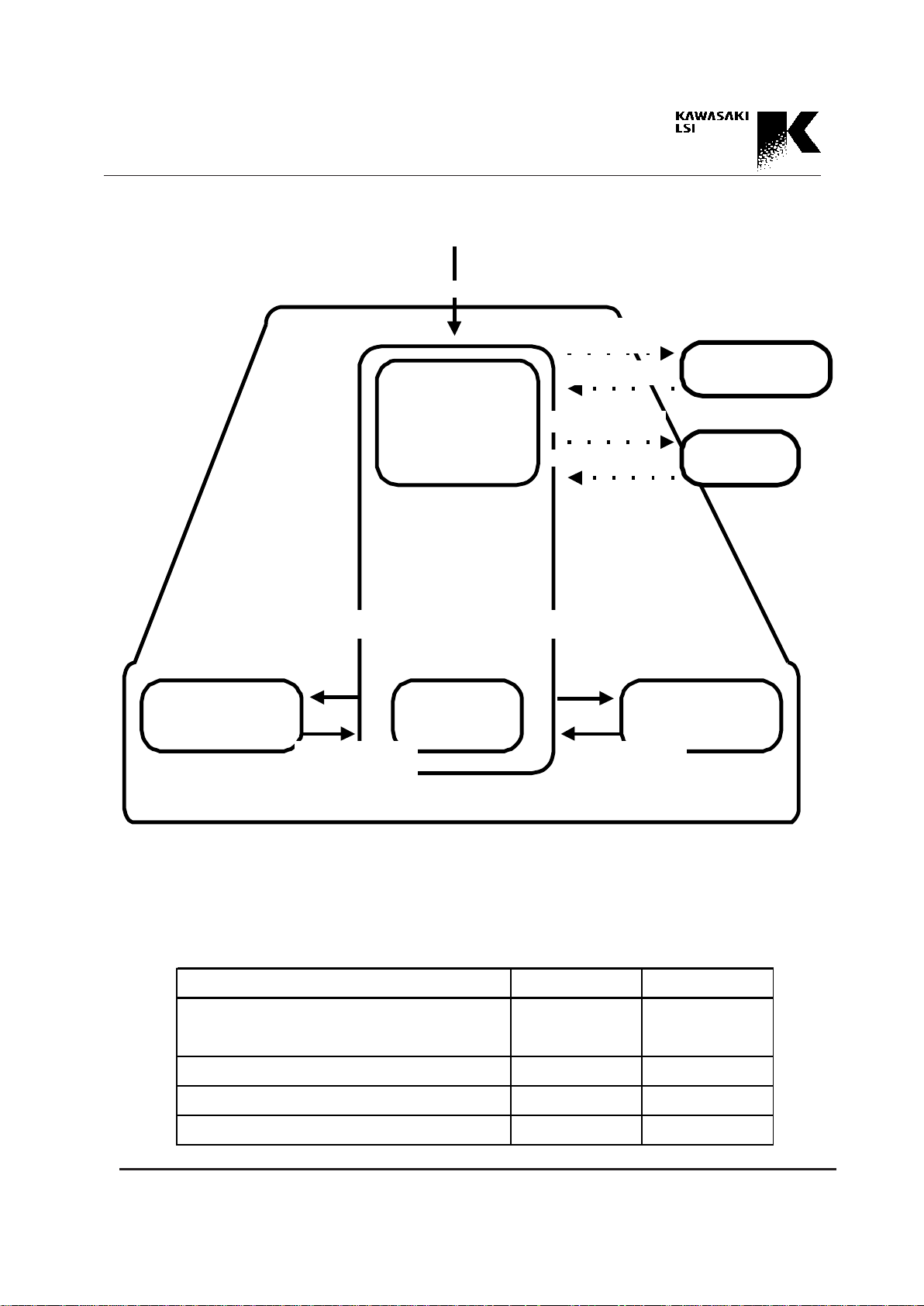
Address Processor KE5B256B1
Table 4.4.1 IPBUSY_/OPACT_, OPBUSY_/IPACT_ in external arbitration
* Device reset RST_pulse or SRST command
** Sequence pointer reset SQRST_pulse or SSQRST command
Power ON *SP/TP_
p
ull u
p
Device Reset
DEVID sub-
mode
Waiting state for
IP/OP sequence
(No CPU, IP, OP, and IOP modes)
IP sequence
OP
sequence
· RD_pulse · WR pulse
· Sequence pointer
reset**
· End of OP
sequence
Normal operation state
· Sequence pointer
reset**
· End of IP sequence
TC sub-mode
· STR_DEVID
command
· END_DEVID
command
· STR_TC command
· END_TC command
Fig. 4.4.1 State Diagram in external arbitration
IPBU SY_/OPACT_ OPBUSY_/IPACT _
Both IP seq uen ce and OP sequ en ce are no t run n ing
(Init ia l stat e af t er device reset) H H
IP sequence running H L
OP sequence running L H
Both IP seq uen ce and OP sequ en ce are run n in g
LL
5-1
Address Processor KE5B256B1
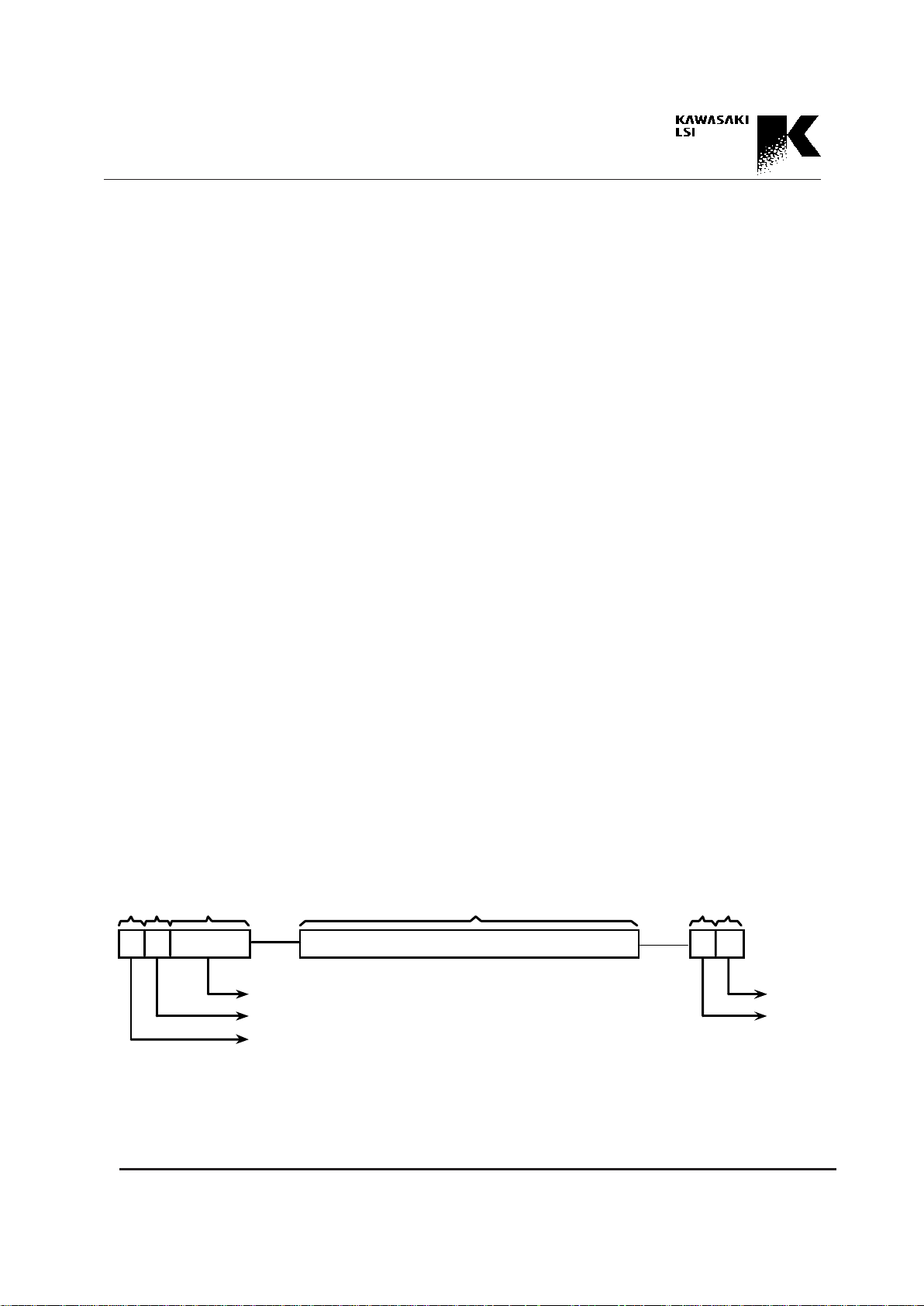
Fig. 5.1.1 Word structure of CAM
5. CAM Table
The KE5B256B1 has a 256-kbit CAM and stores the data
table the searched in the CAM. This chapter discusses the
data table (CAM table) construction and relation between
searches and the CAM table.
5.1 Entry and Segment
The CAM table is made up logically of many entries. In
searching, part or all data of the entries are compared simultaneously with all entries in the CAM.
As a device feature, the width (data bit of the entry) and
number of the entries can be set flexibly. The entry is made
up of 32-bit segments. Accessing the CAM table and
searching operation are executed by segment unit.
Physically, one segment corresponds to one CAM_word.
The device has 8k (8,192)-CAM_words and can store
256k-bit (32 x 8k) of entry data. Each CAM word is assigned an absolute address (CAM address) of 0H~1FFFH
(0~8192), and not only has segment data space for storing
the entry data, but also has circuit elements for realizing
some functions.
Fig. 5.1-1 shows all the elements comprising a segment. A
detailed discussion is presented below.
Segment Data
The segment data stores the entry data. The width of one
segment datum is 32 bits. The segment data can be used for
CAM or RAM. The segment data operates as CAM in the
search operation. In table read/write, table maintenance,
and outputting of search results, the segment data operates
as RAM. A definition of the distinction of CAM/RAM is
not required.
The methods of addressing when reading/writing segment
data are (1) used the CAM address (absolute address indication) and (2) indication of the address by the segment
number in the entry, using the entry address shown in the
HHA or HEA register (discussed below) as an index.
Boundary Bit
The Boundary Bit is used for segment numbers (discussed
below) and Table Configuration, and can be read or written
only in the TC sub-mode.
Segment Number
The 3-bit width segment number indicates the number of
the segment in the entry. The segment data can be read or
written only in the TC sub-mode.
32 bits
Boundary Bit
Empty Bit
Segment data
1 bit 1 bit
Segment number
Access Bit
Hit Flag
1 bit 1 bit 3 bits
 Loading...