

Page 1
Ninja ZX-12R
Motorcycle
Service Manual
Page 2

Page 3
Quick R eference Guide
General Information 1 j
Periodic Maintenance 2 j
Fuel System (DFI) 3 j
Cooling System 4 j
Engine Top End 5 j
Clutch 6 j
Engine Lubrication System 7 j
Engine Removal/Installation 8 j
This quick reference guide will assist
you in locating a desired topic or procedure.
•Bend the pages back to match the
black tab of the desired chapter number with the black tab on the edge at
each table of contents page.
•Refer to the sectional table of contents
for the exact pages to locate the specific topic required.
Crankshaft/Transmission 9 j
Wheels/Tires 10 j
Final Drive 11 j
Brakes 12 j
Suspension 13 j
Steering 14 j
Frame 15 j
Electrical System 16 j
Troubleshooting 17 j
Page 4

Page 5

Ninja ZX-12R
Motorcycle
Service Manual
All r ights reserved. No parts of this publication may be reproduced, stored in a retrieval system, or
transmitted in any form or by any means, electronic mechanical photocopying, recording or otherwise,
without the prior written permission of Quality Assurance Department/Consumer Products & Machinery
Company/Kawasaki Heavy Industries, Ltd., Japan.
No liability can be accepted for any inaccuracies or omissions in this publication, although every possible
care has been taken to make it as complete and accurate as possible.
The right is reserved to make changes at any time without prior notice and without incurring an obligation
to make such changes to products manufactured previously. See your Motorcycle dealer for the latest
information on product improvements incorporated after this publication.
All information contained in this publication is based on the latest product information available at the time
of publication. Illustrations and photographs in this publication are intended for reference use only and may
not depict actual model component parts.
© 2002 Kawasaki Heavy Industries, Ltd. Fourth Edition (1) : Mar. 5, 2004 (K)
Page 6

LIST OF ABBREVIATIONS
A
ABDC after bottom dead center
AC alternating current min minute(s)
ATDC after top dead center N newton(s)
BBDC before bottom dead center Pa pascal(s)
BDC bottom dead center PS horsepower
BTDC before top dead center psi pound(s) per square inch
°C degree(s) Celsius r revolution
DC direct current rpm revolution(s) per minute
F farad(s) TDC top dead center
°F degree(s) Fahrenheit TIR total indicator reading
ft foot, feet V volt(s)
g gram(s) W watt(s)
h hour(s) Ω ohm(s)
L liter(s)
ampere(s)
lb
m
pound(s)
meter(s)
Read OWNER’S MANUAL before operating.
Page 7

EMISSION CONTROL INFORMATION
To protect the environment in which we all live, Kawasaki has incorporated crankcase emission (1) and exhaust emission (2) control systems in compliance with applicable regulations of
the United States Environmental Protection Agency and California Air Resources Board. Additionally, Kawasaki has incorporated an evaporative emission control system (3) in compliance
with applicable regulations of the California Air Resources Board on vehicles sold in California
only.
1. Crankcase Emission Control System
This system eliminates the release of cranckcase vapors into the atmosphere. Instead, the
vapors are routed through an oil separator to the inlet side of the engine. W hile the engine is
operating, the vapors are drawn into combustion chamber, where they are burned along with the
fuel and air supplied by the fuel injection system.
2. Exhaust Emission Control System
This system reduces the amount of pollutants discharged into the atmosphere by the exhaust
of this motorcycle. The fuel, ignition, and exhaust systems of this motorcycle have been carefully
designed and constructed to ensure an efficient engine with low exhaust pollutant levels.
The exhaust system of this model motorcycle manufactured primarily for sale in California in-
cludes a catalytic converter system.
3. Evaporative Emission Control System
Vapors caused by fuel evaporation in the fuel system are not vented into the atmosphere. In-
stead, fuel vapors are routed into the running engine to be burned, or stored in a canister when
the engine is stopped. Liquid fuel is caught by a vapor separator and returned to the fuel tank.
The Clean Air Act, which is the Federal law covering motor vehicle pollution, contains what is
commonly referred to as the Act’s " tampering provisions."
"Sec. 203(a) The following acts and the causing thereof are prohibited...
(3)(A) for any person to remove or render inoperative any device or element of design installed
on or in a motor vehicle or motor vehicle engine in compliance with regulations under this
title prior to its sale and delivery to the ultimate purchaser, or for any manufacturer or dealer
knowingly to remove or render inoperative any such device or element of design after such
sale and delivery to the ultimate purchaser.
(3)(B) for any person engaged in the business of repairing, servicing, selling, leasing, or trading
motor vehicles or motor vehicle engines, or who operates a f leet of m otor vehicles knowingly to remove or render inoperative any device or element of design installed on or in a
motor vehicle or motor vehicle engine in compliance with regulations under this title following its sale and delivery to the ultimate purchaser..."
NOTE
The phrase "remove or render inoperative any device or element of design" has been generally
○
interpreted a s follows :
1. Tampering does not include the temporary removal or rendering inoperative of devices or elements of design in o rder to perform maintenance.
2. Tampering could include:
a.Maladjustment of vehicle components such that the emission standards are ex-
ceeded.
b.Use of replacement parts or accessories which adversely affect the performance
or durability of the motorcycle.
c.Addition of components or accessories that result in the vehicle exceeding the stan-
dards.
d.Permanently removing, disconnecting, or rendering inoperative any component or
element of design of the emission control systems.
Page 8

WE RECOMMEND THAT ALL DEALERS OBSERVE THESE PROVISIONS OF FEDERAL LAW,
THEVIOLATIONOFWHICHISPUNISHABLEBYCIVILPENALTIESNOTEXCEEDING
$10,000 PER VIOLATION.
TAMPERING WITH NOISE CONTROL SYSTEM PROHIBITED
Federal law prohibits the following acts or the causing thereof: (1) The removal or rendering
inoperative by any person other than for purposes of maintenance, repair, or replacement, of any
device or element of design incorporated into any new vehicle for the purpose of noise control
prior to its sale or delivery to the ultimate purchaser or while it is in use, or (2) the use of the
vehicle after such device or element of design has been removed or rendered inoperative by
any person.
Among those acts presumed to constitute tampering are the acts listed below:
Replacement of the original exhaust system or muffler with a component not in compliance
•
with Federal regulations.
Removal of the muffler(s) or any internal portion of the muffler(s).
•
Removal of the air box or air box cover.
•
Modifications to the muffler(s) or air inlet system by cutting, drilling, or other means if such
•
modifications result in increased noise levels.
Page 9
Foreword
This manual is designed primarily for use by
trained mechanics in a properly equipped shop.
However, it contains enough detail and basic information to make it useful t o the owner who desires to perform his own basic maintenance and
repair work. A basic knowledge of mechanics,
the proper use of tools, and workshop procedures must be understood in order to carry out
maintenance and repair satisfactorily. Whenever the owner has insufficient experience or
doubts his ability to do the work, all adjustments, maintenance, and repair should be carried out only by qualified mechanics.
In order to perform the work efficiently and
to avoid costly mistakes, read the text, thoroughly familiarize yourself with the procedures
before starting work, and then do the work carefully in a clean area. Whenever special tools or
equipment are specified, do not use makeshift
tools or equipment. Precision measurements
can only be made if the proper instruments are
used, and the use of substitute tools may adversely affect safe operation.
For the duration of the warranty period,
we recommend that all repairs and scheduled
maintenance be performed in accordance with
this service manual. Any owner maintenance or
repair procedure not performed in accordance
with this manual may void the warranty.
To get the longest life out of your vehicle:
Follow the Periodic M aintenance Chart in the
•
Service Manual.
Be alert for problems and non-scheduled
•
maintenance.
Use proper tools and genuine Kawasaki Mo-
•
torcycle parts. Special tools, gauges, and
testers that are necessary when servicing
Kawasaki motorcycles are introduced by the
Special Tool Catalog or Manual. Genuine
parts provided as spare parts are listed in the
Parts Catalog.
Follow the procedures in this manual care-
•
fully. Don’t take shortcuts.
Remember to keep complete records of main-
•
tenance and repair with dates and any new
parts installed.
How to Use This Manual
In this manual, the product is divited into its
major systems and these systems make up
the manual’s chapters. The Quick Reference
Guide shows you all of the product’s system
and assists in locating their chapters. Each
chapter in turn has its own comprehensive
Table of Contents.
For example, if you want ignition coil information, use the Quick Reference Guide to locate
the Electrical System chapter. Then, use the
Table of Contents on the first page of the chapter to find the Ignition Coil section.
Whenever you see these WARNING and
CAUTION symbols, heed their instructions!
Always follow safe operating and maintenance
practices.
WARNING
This warning symbol identifies special
instructions or procedures which, if not
correctly followed, could result in per-
sonal injury, or loss of life.
CAUTION
This caution sym bol identifies special
instructions or procedures which, if not
strictly observed, could result in dam-
age to or destruction of equipment.
This m anual contains four more symbols (in
addition to WARNING and CAUTION) which will
help you distinguish different types of information.
NOTE
This note symbol indicates points of par-
○
ticular interest for more efficient and con-
venient operation.
Indicates a procedural step or work to be
•
done.
Indicates a procedural sub-step or how to do
○
the work of the procedural step it follows. It
also precedes the text of a NOTE.
Indicates a conditional step or what action to
take based on the results of the test or inspec-
tion in the procedural step or sub-step it fol-
lows.
In most chapters an exploded view illustration
of the system components follows the Table of
Contents. In these illustrations you will find the
instructions indicating which parts require specified tightening torque, oil, grease or a locking
agent during assembly.
Page 10

Page 11

GENERAL INFORMATION 1-1
General Information
Table of Contents
Before Servicing ..................................................................................................................... 1-2
Model Identification................................................................................................................. 1-5
General Specifications............................................................................................................ 1-6
Technical Information – KAWASAKI LOW EXHAUST EMISSION SYSTEM ......................... 1-9
Technical Information – Monocoque Frame . .......................................................................... 1-12
Technical Information – Spark Plug ........................................................................................ 1-13
Technical Information – Immobilizer System (ZX1200-B3)..................................................... 1-14
Torque and Locking Agent...................................................................................................... 1-17
Special Tools and Sealant ...................................................................................................... 1-22
Cable, W ire, and Hose Routing (ZX1200-B1/B2) ................................................................... 1-29
Cable, W ire, and Hose Routing (ZX1200-B3) ........................................................................ 1-46
Unit Conversion Table ............................................................................................................ 1-60
1
Page 12

1-2 GENERAL INFORMATION
Before Servicing
Before starting to service a motorcycle, careful reading of the applicable section is recommended to
eliminate unnecessary work. Photographs, diagrams, notes, cautions, warnings, and detailed descriptions have been included wherever necessary. Nevertheless, even a detailed account has limitations,
a certain amount of basic knowledge is also required for successful work.
Especially note the following:
(1) Dirt
Before removal and disassembly, clean the motorcycle. Any dirt entering the engine or other
parts will work as an abrasive and shorten the life of the motorcycle. For the same reason, before
installing a new part, clean off any dust or metal filings.
(2) Battery Cables
Disconnect the ground (–) cable f rom the battery before performing any disassembly operations
on the motorcycle. This prevents the engine from accidentally turning over while work is being
carried out, sparks from being generated while disconnecting the leads from electrical parts, as
well as damage to the electrical parts themselves. For reinstallation, first connect the positive
cable to the positive (+) terminal of the battery.
(3) Installation, Assembly
Generally, installation or assembly is the reverse of removal or disassembly. But if this Service
Manual has installation or assembly procedures, follow them. Note parts locations and cable,
lead, and hose routing during removal or disassembly so they can be installed or assembled in
the same way. It is preferable to mark and record the locations and routing as much as possible.
(4) Tightening Sequence
Generally, when installing a part with several bolts, nuts, or screws, start them all in their holes
and tighten them to a snug fit. Then tighten them evenly in a cross pattern. This is to avoid
distortion of the part and/or causing gas or oil leakage. Conversely when loosening the bolts,
nuts, or screws, first loosen all of them by about a quarter turn and then remove them. Where
there is a tightening sequence indication in this Service Manual, the bolts, nuts, or screws must
be tightened in the order and method indicated.
(5) Torque
When torque values are given in this Service Manual, use them. Either too little or too much
torque may lead to serious damage. Use a good quality, reliable torque wrench.
(6) Force
Common sense should dictate how much force is necessary in assembly and disassembly. If
a part seems especially difficult to remove or install, stop and examine what m ay be causing the
problem. Whenever tapping is necessary, tap lightly using a wooden or plastic-faced mallet. Use
an impact driver for screws (particularly for the removal of screws held by a locking agent) in order
to avoid damaging the screw heads.
(7) Edges
Watch for sharp edges, especially during major engine disassembly and assembly. Protect your
hands with gloves or a piece of thick cloth when lifting the engine or turning it over.
(8) High-Flash Point Solvent
A high-flash point solvent is recommended to reduce fire danger. A commercial solvent commonly available in North America is Stoddard solvent (generic name). Always follow manufacturer
and container directions regarding the use of any solvent.
(9) Gasket, O-ring
Do not reuse a gasket or O-ring once it has been in service. The mating surfaces around the
gasket should be free of foreign matter and perfectly smooth to avoid oil or compression leakage.
(10)Liquid Gasket, Non-Permanent Locking Agent
Follow manufacturer’s directions for cleaning and preparing surfaces where these compounds
will be used. Apply sparingly. Excessive amounts may block engine oil passages and cause serious damage. An example of non-permanent locking agent commonly available in North America
is Loctite Lock’n Seal (Blue).
(11) Press
A part installed using a press or driver, such as a wheel bearing, should first be coated with oil
on its outer or inner circumference so that it will go into place smoothly.
Page 13
GENERAL INFORMATION 1-3
Before Servicing
(12)Ball Bearing and Needle Bearing
Do not remove a ball bearing or a needle bearing unless it is absolutely necessary. Replace
any ball or needle bearings that were removed with new ones, as removal generally damages
bearings. Install bearings with the marked side facing out applying pressure evenly with a suitable
driver. Only press on the race that forms the press fit with the base component to avoid damaging
the bearings. This prevents severe stress on the balls or needles and races, and prevent races
and balls or needles from being dented. Press a ball bearing until it stops at the stopper in the
hole or on the shaft.
(13)Oil Seal and Grease Seal
Replace any oil or grease seals that were removed with new ones, as removal generally damages seals. When pressing in a seal which has manufacturer’s marks, press it in with the marks
facing out. Seals should be pressed into place using a suitable driver, which contacts evenly with
the side of seal, until the face of the seal is even w ith the end of the hole. Before a shaft passes
through a seal, apply little high temperature grease on the lips to reduce rubber to metal friction.
(14)Circlip, Retaining Ring, and Cotter Pin
Replace any circlips and retaining rings, and cotter pins that were removed with new ones, as
removal weakens and deforms them. When installing circlips and retaining rings, take care to
compress or expand them only enough to install them and no more.
(15)Lubrication
Engine wear is generally at its maximum while the engine is warming up and before all the
rubbing surfaces have an adequate lubricative film. During assembly, oil or grease (whichever
is more suitable) should be applied to any rubbing surface which has lost its lubricative film. Old
grease and dirty oil should be cleaned off. Deteriorated grease has lost its lubricative quality and
may contain abrasive foreign particles.
Don’t use just any oil or grease. Some oils and greases in particular should be used only in
certain applications and may be harmful if used in an application for which they are not intended.
This manual makes reference to molybdenum disulfide grease (MoS
oil in the assembly of certain engine and chassis parts. The molybdenum disulfide oil is a mixture
of engine oil and molybdenum disulfide grease with a weight ratio (10 : 1), which can be made in
your work shop. Always check manufacturer recommendations before using such special lubricants.
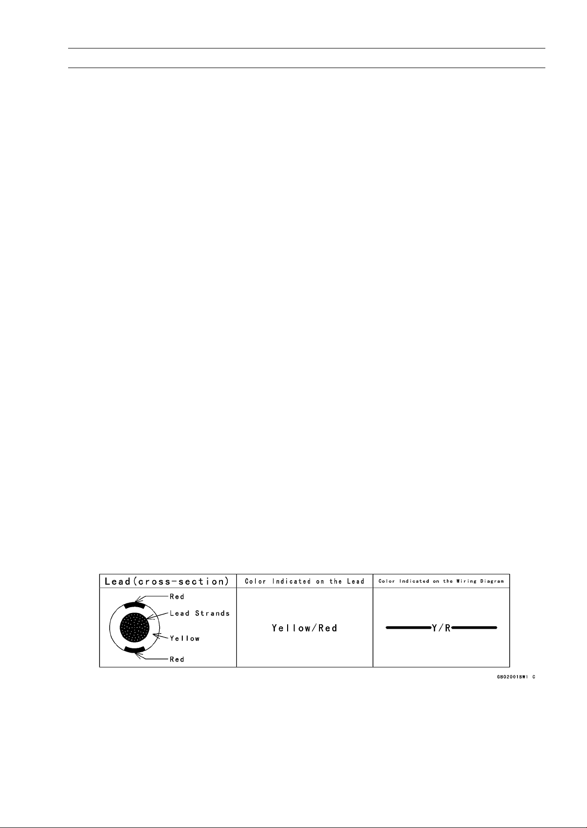
(16)Electrical Leads
All the electrical leads are either single-color or two-color and, with only a few exceptions, must
be connected to leads of the same color. On any of the two-color leads there is a greater amount
of one color and a lesser amount of a second color, so a two-color lead is identified by first the
primary color and then the secondary color. For example, a yellow lead with thin red stripes is
referred to as a "yellow/red" lead; it would be a "red/yellow" lead if the colors were reversed to
make red the main color .
2) and molybdenum disulfide
(17)Replacement Parts
When there is a replacement instruction, replace these parts with new ones every time they are
removed. These replacement parts will be damaged or lose their original function once removed.
Page 14

1-4 GENERAL INFORMATION
Before Servicing
(18)Inspection
When parts have been disassembled, visually inspect these parts for the following conditions
or other damage. If there is any doubt as to the condition of them, replace them with new ones.
Abrasion Crack Hardening Warp
Bent Dent Scratch Wear
Color change Deterioration Seizure
(19)Specifications
Specification terms are defined as follows:
"Standards" show dimensions or performances which brand-new parts or systems have.
"Service Limits" indicate the usable limits. If the measurement shows excessive wear or dete-
riorated performance, replace the damaged parts.
(20)Instrument
Use a meter that has enough accuracy for an accurate measurement.
Read the manufacturer’s instructions thoroughly before using the meter.
Incorrect values may lead to improper adjustments.
Page 15
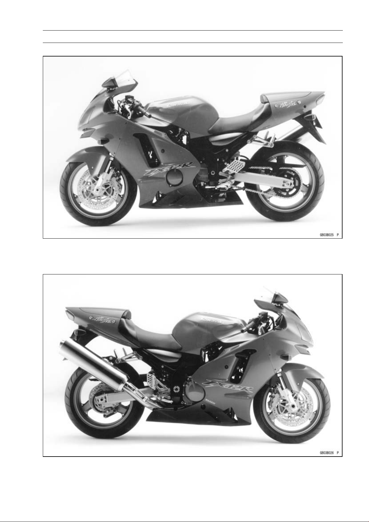
Model Identification
ZX1200-B1 Left Side View
GENERAL INFORMATION 1-5
ZX1200-B1 Right Side View
Page 16

1-6 GENERAL INFORMATION
General Specifications
Items ZX1200-B1 ∼ B3
Dimensions
Overall Length 2 085 mm (82.09 in.)
Overall Width 740 mm (29.13 in.)
Overall Height 1 200 mm (47.24 in.)
Wheelbase 1 450 mm (57.09 in.)
Road Clearance 120 mm (4.72 in.)
Seat Height 820 mm (32.28 in.)
Dry Mass 210 kg (463 lb)
Curb Mass:
Front 125 kg (276 lb)
Rear 121 kg (267 lb)
Fuel Tank Capacity 19.0 L (5.0 US gal)
Performance
Minimum Turning Radius 3.0 m (9.8 ft)
Engine
Type 4-stroke, DOHC, 4-cylinder
Cooling System Liquid-cooled
Bore and Stroke 83.0 × 55.4 mm (3.27 × 2.18 in.)
Displacement 1 199 mL (73.16 cu in.)
Compression Ratio 12.2
Maximum Horsepower (H) 131 kW (178 PS) @9 500 r/min (rpm),
(AU) ZX1200-B1/B2: 130 kW (177 PS) @10 500 r/min (rpm),
(AU) ZX1200-B3: 131 kW (178 PS) @10 500 r/min (rpm),
(HR) 78.2 kW (106.4 PS) @8 500 r/min (rpm),
(MY) ZX1200-B1/B2: 131 kW (178 PS) @ 9 500 r/min ( rpm),
(MY) ZX1200-B3: 128 kW (174 PS) @9 500 r/min (rpm)
(US), (CA) – – –
Maximum Torque (H, AU) 134 N·m (13.7 kgf·m, 99 ft·lb) @7 500 r/min (rpm),
(MY) ZX1200-B1/B2: 134 N·m (13.7 kgf·m, 99 ft·lb) @7 500
r/min (rpm),
(MY) ZX1200-B3: 130 N·m ( 13.3 kgf·m, 96 ft·lb) @7 500 r/min
(rpm),
(HR) 111 N·m (11.3 kgf·m, 82 ft·lb) @5 000 r/min (rpm),
(US), (CA) – – –
Carburetion System FI (Fuel Injection), ZX1200-B1/B2: MIKUNI 46 EIS × 4
ZX1200-B3: KEIHIN ( 46 × 4)
Starting System Electric starter
Ignition System Battery and coil (transistorized)
Timing Advance Electronically advanced (digital igniter in ECU)
Ignition Timing 10° BTDC @1 000 r/min (rpm)
Spark Plugs NGK CR9EKPA
Cylinder Numbering Method Left to right, 1-2-3-4
Firing Order 1-2-4-3
Page 17

GENERAL INFORMATION 1-7
General Specifications
Items ZX1200-B1 ∼ B3
Valve Timing:
Inlet:
Open 46° BTDC
Close 74° ABDC
Duration 300°
Exhaust:
Open 69° BBDC
Close 45° ATDC
Duration 294°
Lubrication System Forced lubrication (wet sump with cooler)
Engine Oil:
Grade API SE, SF or SG
API SH or SJ with JASO MA
Viscosity
Capacity 3.6 L (3.8 US qt)
Drive Train
Primary Reduction System:
Type Gear
Reduction Ratio 1.596 (83/52)
Clutch Type Wet, multi disc
Transmission:
Type 6-speed, constant mesh, return shift
Gear Ratios:
1st 2.429 (34/14)
2nd
3rd
4th
5th 1.130 (26/23)
6th 1.033 (31/30)
Final Drive System:
Type Chain drive
Reduction Ratio 2.556 (46/18)
Overall Drive Ratio 4.215 @Top gear
Frame
Type Press backbone
Caster (Rake Angle) 23.5°
Trail
Front Tire:
Type Tubeless
Size 120/70 ZR17 M/C (58W)
Rear Tire:
Type Tubeless
Size 200/50 ZR17 M/C (75W)
SAE 10W-40
1.824 (31/17)
1.440 (36/25)
1.250 (30/24)
98 mm (3.86 in.)
Page 18

1-8 GENERAL INFORMATION
General Specifications
Items ZX1200-B1 ∼ B3
Front Suspension:
Type
Wheel Travel
Rear Suspension:
Type Swingarm (uni-trak)
Wheel Travel 140 mm (5.51 in.)
Brake Type:
Front Dual discs
Rear Single disc
Electrical Equipment
Battery 12 V 12 Ah
Headlight:
Type Semi-sealed beam
Bulb 12 V 60/55 W (quartz-halogen) × 2
Tail/Brake Light 12 V 5/21 W × 2
Alternator:
Type Three-phase AC
Rated Output 31 A/14 V @ 5 000 r/min (rpm)
Telescopic fork (upside-down)
120 mm (4.72 in.)
Specifications are subject to change without notice, and may not apply to every country.
AU: Australian Model
US: U.S.A. Model
CA: Canadian Model
MY: Malaysian Model
HR: WVTA Approval Model, Honeycomb Catalytic Converter (Restricted Power)
H: WVTA Approval Model, Honeycomb Catalytic Converter
Page 19
GENERAL INFORMATION 1-9
Technical Information – KAWASAKI LOW EXHAUST EMISSION SYS TEM
Since the emission regulations become more severe, Kawasaki has adopted a type of simplified
KAWASAKI LOW EX HAUST EMISSION SYSTEM (KLEEN), which have no catalyst protection system, according to each regulation of different countries.
The muffler with built-in catalyst has the same durability as the conventional muffler, however, do
not use leaded gasoline and do not coast with the ignition system OFF. Running the engine without
ignition damages catalyst.
Refer to the ZX900E Service Manual (Part No. 99924-1255) for more information about the KLEEN
(theory, maintenance, and handling precautions), including the secondary air injection system.
Honeycomb Type Catalytic Converter
The converter is a three-way catalytic converter, and its surface is covered with alumina upon which
○
platinum and rhodium are applied, and has a cylindrical metalic honeycomb structure made by bend-
ing a corrugated sheet and a flat sheet of stainless steel into a spiral of increasing diameter. The
honeycomb structure is convenient for the catalytic converter because it has a large surface area
but small size to react effectively and has low exhaust resistance. In addition, its inherent strength
helps resist vibration, and has simple structure welded directly on the silencer.
Generally, the temperature of t he exhaust gas must be higher than activation temperature, so the
○
converters are installed in the exhaust manifold rear end where the temperature of exhaust gas is
still high. And, the converters will be activated even under low load conditions.
After the exhaust gas is diluted with the secondary air injection, the catalytic converter works well
○
because of rich oxygen to reduce CO, HC, and NO
emission within regulation.
This type of converter works more efficiently as a three-way catalytic converter to reduce CO, HC,
○
and NO
x than the pipe type catalytic converter because of its more and denser catalysts.
x. Accordingly, we can keep the exhaust gas
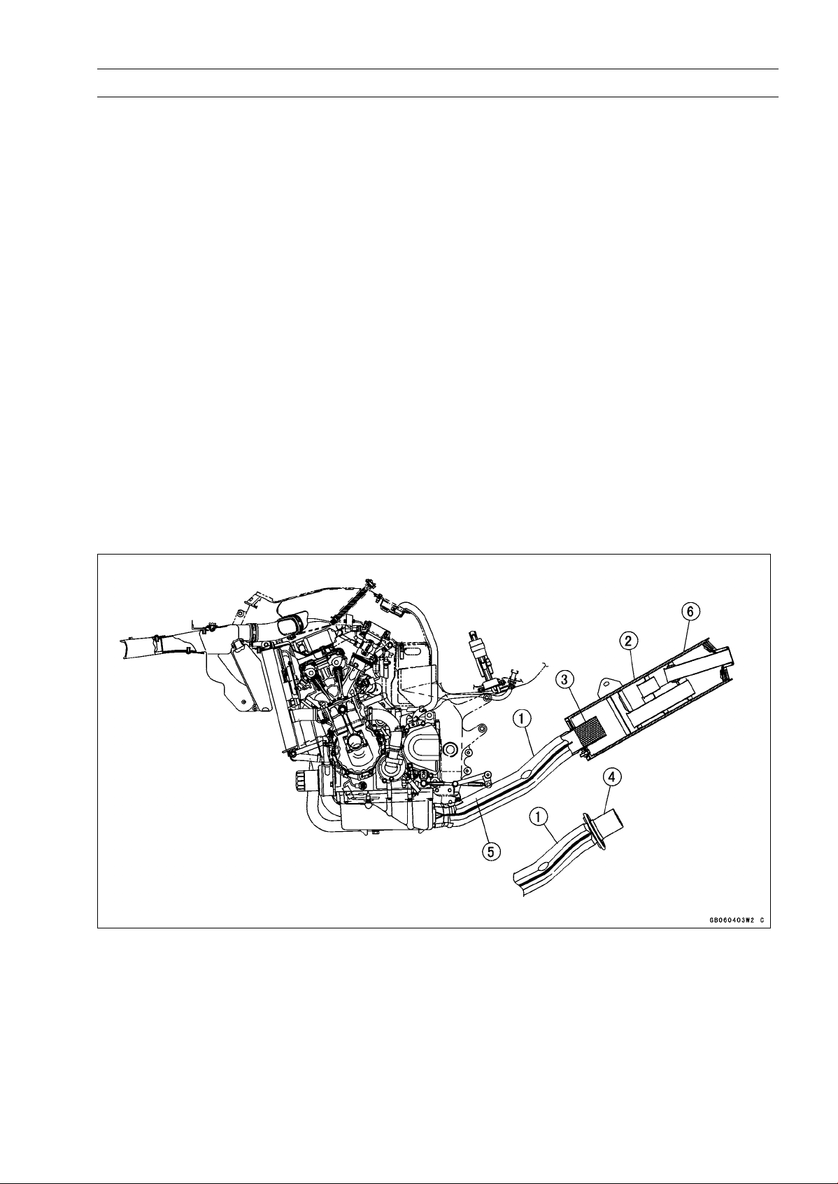
1. Manifold
2. Silencer
3. Honeycomb Type Catalyst
4. Non-Catalyst
5. Mark for Manifold
6. Mark for Silencer
Page 20
1-10 GENERAL INFORMATION
Technical Information – KAWASAKI LOW EXHAUST EMISSION SYSTEM
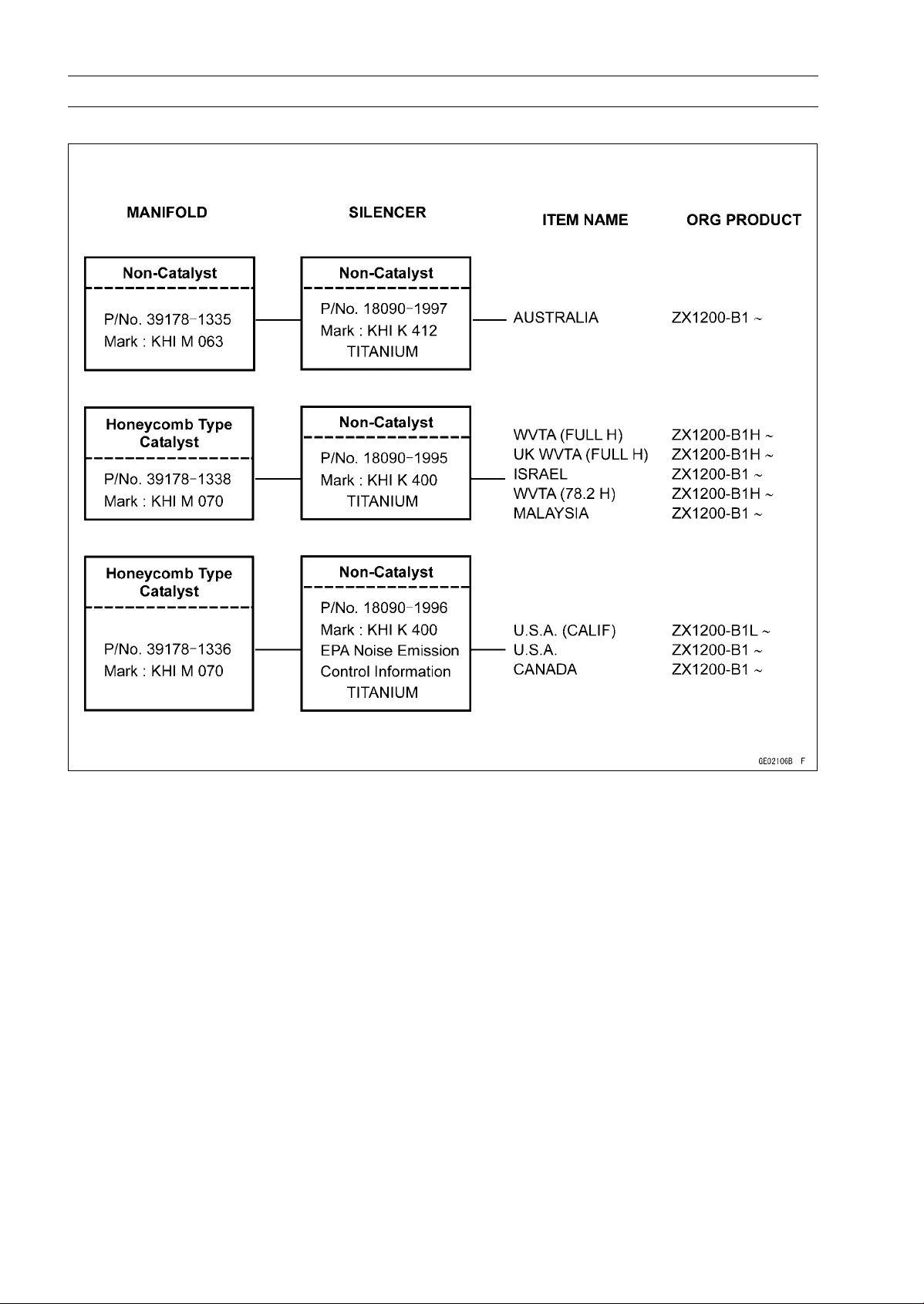
Exhaust System (ZX1200-B1/B2)
78.2: Horsepower 78.2 kW (106.3 ps)
Full: Full Power
H: Honeycomb Type Catalyst
UK: United Kingdom Model
Page 21
GENERAL INFORMATION 1-11
Technical Information – KAWASAKI LOW EXHAUST EMISSION SYS TEM
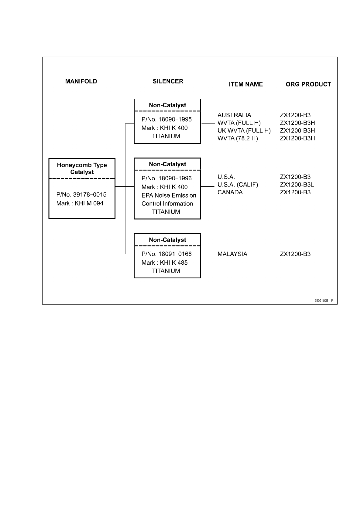
Exhaust System (ZX1200-B3)
78.2: Horsepower 78.2 kW (106.3 ps)
Full: Full Power
H: Honeycomb Type Catalyst
UK: United Kingdom Model
Page 22
1-12 GENERAL INFORMATION
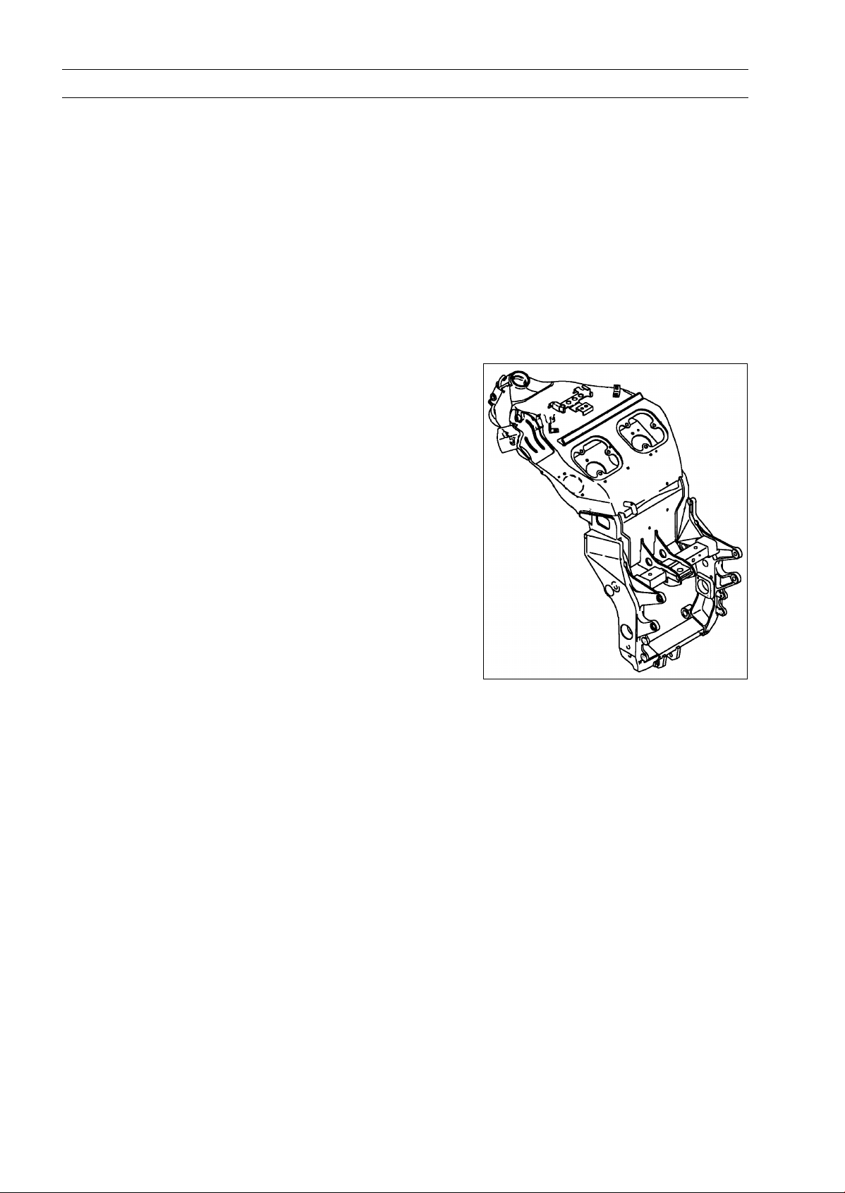
Technical Information – Monocoque Frame
Why a monocoque? Like all breakthrough innovations, the choice appears quite obvious after the
fact. When large-section aluminium spars are wrapped around an already wide, large-displacement
in-line Four engine, the resulting package must of necessity be wide. The ZX-12R’s all-aluminium box
-section monocoque chassis eliminates these perimeter spars in favor of a large box section running
over the top of the engine.
This frame design surpasses the levels of chassis stiffness and strength associated with conventional aluminium twin-beam frames, but with considerably less breadth. Without the twin beams or
other frame elements running around the side of the engine, the fairing can be much narrower, resulting in a much slimmer overall package and significantly better aerodynamics. Further, in a radical
departure, the hollow structure also doubles as an airbox for the Ram Air system, eliminating the need
for a space-consuming, conventional airbox.
And ultimately, it is the synergy of combining a compact, massively powerful engine with this super
stiff and slim chassis structure that explains much of the ZX-12R’s superlative high-speed performance.
All-new frame-integrated Ram Air system adds consider-
•
able horsepower in the higher speed ranges.
Monocoque frame allows for the use of perfectly straight,
•
highly efficient inlet ports.
Using the frame backbone as an airbox saves space and
•
creates a very efficient airbox.
Battery mounts inside the frame and the battery cover is
•
a structural element.
Revolutionary new all-aluminum monocoque frame for
•
high rigidity and lightweight.
Huge box section and heat-freated cast steering
•
head/swingarm pivot areas realize an extremely
stiff structure and contribute to the ZX-12R’s superb
high-speed stability and nimble, s uper sport handling
performance.
By eliminating the dual large-section beams of conven-
•
tional aluminum frames, this frame design makes possi-
ble a much narrower and more compact overall package
and greatly improves aerodynamics.
Page 23
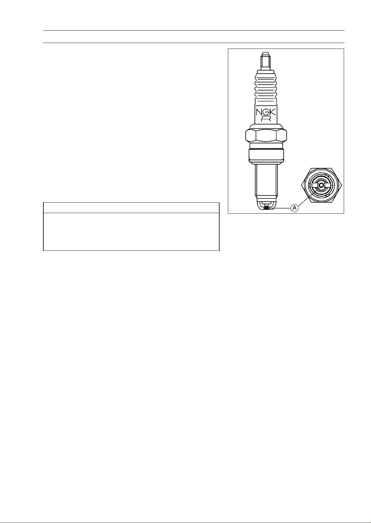
Technical Information – Spark Plug
ZX1200-B1 is equipped with the Kawasaki recommended
spark plug (NGK CR9EKPA). By using the Kawasaki recommended spark plug, the i dling stability, the fuel consumption improvement, and the maintenance free spark plug is
planed.
This spark plug is calculated 3 or 4 times as durable as
the usual one (NGK CR9EK).
Feature
1. This spark plug is more superior t o the usual one with
the ignition for the ignition point protruding.
2. Further, this spark plug is superior to the usual one with
the endurance for the Pt alloy [A] covering around the
center electrode and for the opposed area improvement
of the side electrodes.
Specification
1. Standard Spark Plug CR9EKPA, two side electrodes,
M10 threads
2. Hotter Spark Plug CR8EKPA, two side electrodes, M10
threads
GENERAL INFORMATION 1-13
CAUTION
Use only the recommender spark plug. Do not use
other spark plug, even though it may fit, because it
could cause the engine failure of the idling stability,
etc.
Page 24
1-14 GENERAL INFORMATION
Technical Information – Immobilizer System (ZX1200-B3)
Overview
This system provides a theft proof device by means of matching a code between the inbuilt key
transponder and the ECU (Electronic Control Unit). If t his code does not match, the fuel pump, injectors, ignition system and sub-throttle valve actuator will not operate and the engine will not start.
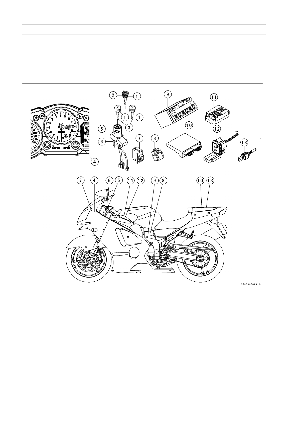
Related Parts and Function
1. Transponder (Inside Keys)
2. Master Key
3. User Keys
4. FI Indicator Light
5. Immobilizer Antenna
6. Ignition Switch
7. Immobilizer Amplifier
Master Key (1 piece)
The master key (colored red) has an inbuilt transponder, containing a master key code. These
codes are unique to each key. This code and an additional two user key codes must be registered
in the ECU for the system to operate. The master key is necessary when registering user keys and
should not be used as the main key to start the motorcycle except in emergencies (loss or damage of
user keys). It should be kept in a safe place.
8. Starter Relay
9. Battery
10. Electronic Control Unit (ECU)
11. J unction Box
12. Fuse Box
13. Immobilizer/Kawasaki Diagnostic System
Connector
Page 25
GENERAL INFORMATION 1-15
Technical Information – Immobilizer System (ZX1200-B3)
Transponder (in Keys)
The transponder (made by Texas Instruments, Inc.) has an integrated circuit with a unique code
that also calculates data sent by the ECU. When the ignition switch is turned ON, the transponder
is excited by the radio wave transmitted from the antenna and then transmits a unique code to the
antenna.
User Key (2 pieces)
The user keys (colored black) should be used when riding the motorcycle. These keys have unique
codes which differ from the master key. Up to a maximum of five user key codes can be stored by
the ECU at any one time. These codes can not be registered to the ECU without firstly registering the
master key c ode.
Antenna
The antenna transmits a radio wave to excite the transponder, receives the code from the t ransponder and then transmits the code to the ECU through the amplifier.
Ignition Switch
The ignition switch turns the main circuit ON and OFF.
Amplifier
The amplifier (which is approximately the same size as a match box), amplifies signals from the
antenna and the ECU.
ECU
The ECU has the capacity to store a maximum of six key code memories (one master and five user
keys). The owner can have a total of five user keys at any one time. The master key memory can not
be rewritten after initial registration, whereas the user key memories can be rewritten as necessary.
When the ECU communicates with the transponder, a cipher generator changes the code every time
it is used to avoid cloning.
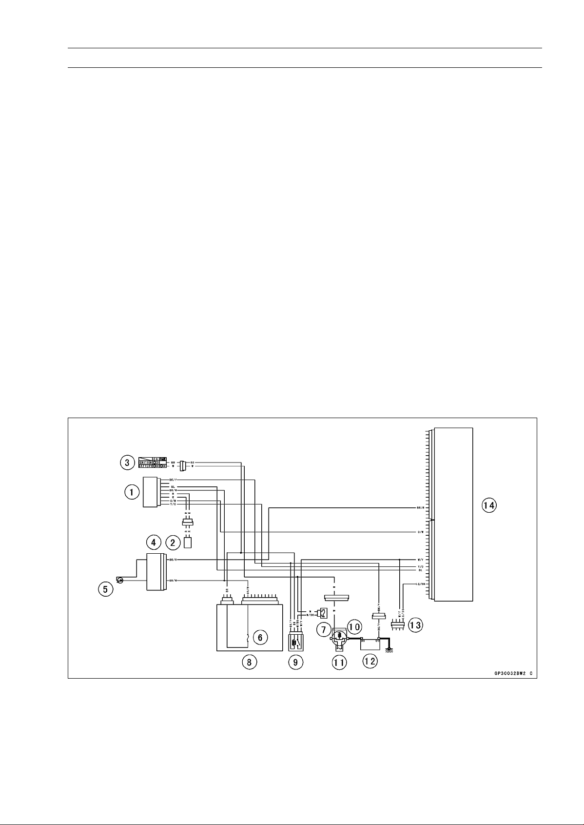
FI Indicator Light
The condition or the failure of the immobilizer system is indicated by various patterns of the FI indicator light blinking.
1. Immobilizer Amplifier
2. Immobilizer Antenna
3. Ignition Switch
4. Meter Unit
5. FI Indicator Light
6. Ignition Fuse 10 A
7. ECU Fuse 15 A
8. Junction Box
9. ECU Main Relay
10. Starter Relay
11. Main Fuse 30 A
12. Battery 12 V 12 Ah
13. Immobilizer/Kawasaki Diagnostic System
Connector
14. Electronic Control Unit (ECU)
Page 26

1-16 GENERAL INFORMATION
Technical Information – Immobilizer System (ZX1200-B3)
Sequence of Operation
1. Turn ON the ignition switch, the ECU, amplifier and antenna start working, and the meter assembly
FI indicator lights up.
2. The transponder excited by radio waves transmitted from the antenna receives the ciphered code
from the ECU.
3. The transponder transmits the calculated result from the key’s unique code to the ECU.
4. The ECU com pares this with its memorized code, and if they match the engine can start. At this
time, the FI indicator in the meter assembly is switched off.
Page 27
GENERAL INFORMATION 1-17
Torque and Lo cking Agent
The following tables list the tightening torque for the major fasteners requiring use of a
non-permanent locking agent or liquid gasket.
Letters used in the “Remarks” column mean:
L: Apply a non-permanent locking agent to the threads.
M: Apply molybdenum disulfide grease.
MO: Apply molybdenum disulfide oil solution.
O: Apply oil to the threads and seating surface.
S: Tighten the fasteners following the specified sequence.
SS: Apply silicone sealant.
St: Stake the fasteners to prevent loosening.
R: Replacement Parts
The table below, relating tightening torque to thread diameter, lists the basic torque for the bolts and
nuts. Use this table for only the bolts and nuts which do not require a specific torque value. All of the
values are for use with dry solvent-cleaned threads.
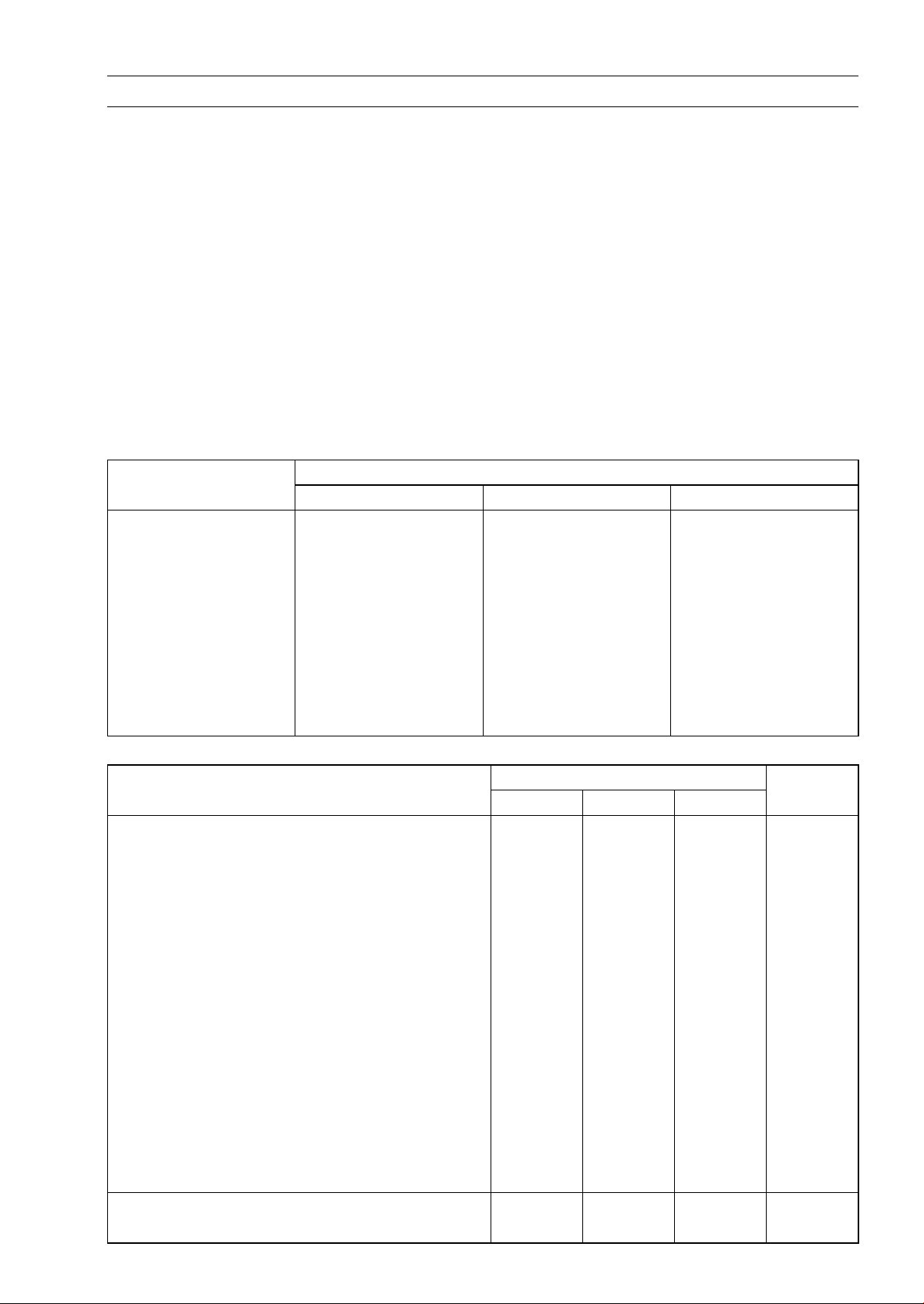
Basic Torque for General Fasteners
Threads Tor qu e
dia.(mm)
5 3.4 ∼ 4.9 0.35 ∼ 0.50 30 ∼ 43 in·lb
6 5.9 ∼ 7.8 0.60 ∼ 0.80 52 ∼ 69 in·lb
8 14 ∼ 19 1.4 ∼ 1.9 10.0 ∼ 13.5
10 25 ∼ 34 2.6 ∼ 3.5 19.0 ∼ 25
12 44 ∼ 61 4.5 ∼ 6.2 33 ∼ 45
14 73 ∼ 98 7.4 ∼ 10.0 54 ∼ 72
16 115 ∼ 155 11. 5 ∼ 16.0 83 ∼ 115
18 165 ∼ 225 17.0 ∼ 23.0 125 ∼ 165
20 225 ∼ 325 23 ∼ 33 165 ∼ 240
N·m
kgf·m ft·lb
Fastener
N·m kgf·m ft·lb
Fuel System (DFI)
Fuel Level Sensor Bolts 6.9 0.70 61 in·lb L
Fuel Pump Bolts 6.9 0.70 61 in·lb L, S
Fuel Hose Clamp Bolts 1.5 0.15 13 in·lb
Inlet Air Pressure Sensor Bolt 12 1.2 106 in·lb
Inlet Air Pressure Sensor Bracket Nut 12 1.2 106 in·lb
Inlet Air Temperature Sensor 7.8 0.80 69 in·lb
Atmospheric Pressure Sensor Bolts 12 1.2 106 in·lb
Gear Position Switch Screws 4.0 0.40 35 in·lb L
Crankshaft Sensor Bolts 6.0 0.60 53 in·lb
Camshaft Position Sensor Bolt 12 1.2 106 in·lb
Crankshaft Position Sensor Rotor Bolt 12 1.2 106 in·lb L
Delivery Pipe Screws (ZX1200-B1/B2) 5.0 0.50 44 in·lb
Delivery Pipe Screws (ZX1200-B3) 3.4 0.35 30 in·lb
Nipple Assy Screws 3.5 0.35 31 in·lb
Cooling System
Coolant Hose Clamp Screws 2.0 0.20 18 in·lb
Torque
Remarks
Page 28

1-18 GENERAL INFORMATION
Torque and Locki ng Agent
Fastener
Coolant Fitting Nozzle (ZX1200-B1/B2)
Coolant Drain Plug (Water Pump)
Coolant Drain Plug (Cylinder) 10 1.0 89 in·lb
Radiator Fan Switch 18 1.8 13
Water Temperature Sensor 25 2.5 18 SS
Water Pum p Impeller Bolt 10 1.0 89 in·lb
Water Pum p Cover Bolts 12 1.2 106 in·lb
Coolant Pipe Bolt 12 1.2 106 in·lb
Thermostat Housing Cover Bolts 8.0 0.80 71 in·lb L
Fitting Bolts 12 1.2 106 in·lb
Engine Top End
Spark Plugs 13 1.3 115 in·lb
Air Suction Valve Cover Bolts 12 1.2 106 in·lb
Baffle Plate Bolts 10 1.0 89 in·lb
Cylinder Head Cover Bolts 10 1.0 89 in·lb
Crankshaft Sensor Cover Bolts 15 1.5 11 L
Camshaft Chain Tensioner Mounting Bolts 10 1.0 89 in·lb L
Camshaft Cap Bolts 12 1.2 106 in·lb
Upper Camshaft Chain Guide Bolts 12 1.2 106 in·lb
Front Camshaft Chain Guide Bolt (Upper) 25 2.5 18
Front Camshaft Chain Guide Bolt (Lower) 12 1.2 106 in·lb
Rear Camshaft Chain Guide Bolt 25 2.5 18
Camshaft Position Sensor Bolt 12 1.2 106 in·lb
Camshaft Position Sensor Rotor Bolt 12 1.2 106 in·lb L
Cylinder Head Bolts: M11 First Tighten 23 2.3 17 MO, S
Cylinder Head Bolts: M11 Final Tighten 59 6.0 44 MO, S
Cylinder Head Bolts: M7 20 2.0 15 S
Cylinder Head Jacket Plugs 22 2.2 16 L
Throttle Body Holder Bolts 12 1.2 106 in·lb
Muffler Body Connection Nuts 34 3.5 25
Guard Mounting Bolts 12 1.2 106 in·lb
Exhaust Pipe Holder Studs – – – (Stopped)
Clutch
Clutch Lever Clamp Bolts 7.8 0.80 69 in·lb S
Clutch Cover Bolts 15 1.5 11 L(2)
Clutch Cover Damper Plate Bolts 7.0 0.70 62 in·lb L
Clutch Spring Bolts 8.8 0.90 78 in·lb
Clutch Hub Nut 135 14 100 R
Engine Lubrication System
Oil Level Gauge Bolts
N·m
12 1.2 106 in·lb L
12 1.2 106 in·lb
12 1.2 106 in·lb
Torque
Remarks
kgf·m ft·lb
(Washer)
(Washer)
Page 29

Torque and Lo cking Agent
GENERAL INFORMATION 1-19
Fastener
Oil Filler Plug 1.5 or
Engine Oil Drain Plug 20 2.0 15
Oil Filter (Cartridge Type) 31 3.2 23 EO, R
Oil Cooler Passage Bolt 78 7.8 58 EO
Oil Cooler Mounting Bolts 25 2.5 18 L
Oil Pan Bolts 15 1.5 11 L(1)
Oil Pipe Holder Bolts 12 1.2 106 in·lb L
Oil Pressure Relief Valve 15 1.5 11 L
Oil Pressure Switch 15 1.5 11 SS
Oil Pressure Switch Terminal Screw 1.5 0.15 13 in·lb
Water Pump Impeller Bolt 10 1.0 89 in·lb
Engine Removal/Installation
Engine Mounting Bolts and Nuts: M12 59 6.0 44
Engine Mounting Bolts and Nuts: M8 25 2.5 18
Upper Engine Mounting Bracket Bolt: M12 59 6.0 44
Lower Engine Mounting Bracket Bolt: M10 44 4.5 32
Adjusting Collars 25 2.5 18
Crankshaft/Transmission
Breather Plate Bolts 10 1.0 89 in·lb L
Breather Tube Bracket Bolts 12 1.2 106 in·lb
Crankcase Bolts: M10 50 5.0 37 MO, S
Upper Crankcase Bolts: M8, L85
Upper Crankcase Bolts: M7
Lower Crankcase Bolts: M8, L99
Lower Crankcase Bolts: M7 20 2.0 15 S
Oil Passage Plugs (Each Side) 20 2.0 15 L
Connecting Rod Big End Nuts in the text ← ← ←
Timing Rotor Bolt 39 4.0 29
Starter Torque Limiter Cover Bolts 12 1.2 106 in·lb L
Oil Pressure Switch 15 1.5 11 SS
Gear Positioning Lever Bolt 10 1.0 89 in·lb L
Shift Shaft Return Spring Pin (Bolt) 30 3.0 22 L
Speed Sensor Bolt 12 1.2 106 in·lb L
Shift Drum Bearing Holder Bolt 12 1.2 106 in·lb L
Shift Drum Bearing Holder Screw 5.4 0.55 48 in·lb L
Shift Drum Cam Bolt 12 1.2 106 in·lb L
Balancer Shaft Clamp Lever Bolt 25 2.5 18 L
Balancer Shaft Clamp Bolt 12 1.2 106 in·lb
Oil Pipe Holder Bolts (Crankshaft Pipe) 12 1.2 106 in·lb L
Oil Pipe Holder Bolt (Transmission Pipe)
Oil Nozzle
N·m kgf·m ft·lb
Hand
-Tight
28 2.8 21
25 2.5 18
23 2.3 17
12 1.2 106 in·lb
2.5 0.25 22 in·lb
Torque
0.15 or
Hand
-Tight
Remarks
13 in·lb
or Hand
-Tight
S
S
S
St
Page 30

1-20 GENERAL INFORMATION
Torque and Locki ng Agent
Fastener
Starter Clutch Shaft Bolt
Starter Clutch Shaft Plate Bolt
Wheels/Tires
Front Axle Clamp Bolts 20 2.0 15 AL
Front Axle Nut 125 13 92
Rear Axle Nut 125 13 92
Rear Sprocket Nuts 59 6.0 44
Air Valve Cap 0.15 0.015 1.3 in·lb
Final Drive
Engine Sprocket Nut 127 13 94 MO
Engine Sprocket Cover Bolts 12 1.2 106 in·lb
Chain Guide Bolt 12 1.2 106 in·lb L
Rear Sprocket Nuts 59 6.0 44
Rear Axle Nut 125 13 92
Brakes
Bleed Valves 7.8 0.80 69 in·lb
Brake Hose Banjo Bolts 25 2.5 18
Brake Lever Pivot Bolt 1.2 0.12 11 in·lb Si
Brake Lever Pivot Bolt Locknut 6.0 0.60 52 in·lb
Front Reservoir Cap Screws 1.5 0.15 13 in·lb
Front Brake Light Switch Screw s 1.2 0.12 11 in·lb
Front Master Cylinder Clamp Bolts 8.8 0.90 78 in·lb S
Front Brake Pad Spring Bolts (ZX1200-B1/B2) 3.0 0.30 27 in·lb
Front Caliper Mounting Bolts
Front Caliper Assembly Bolts
Brake Disc Mounting Bolts 27 2.8 20 L
Front Brake Pad Pins (ZX1200-B3) 15 1.5 11
Rear Caliper Mounting Bolts 25 2.5 18
Rear Caliper Assembly Bolts 30 3.0 22
Brake Pedal Mounting Bolt 8.8 0.90 78 in·lb
Rear Master Cylinder Mounting Bolts 25 2.5 18
Rear Master Cylinder Push Rod Locknut 18 1.8 13
Suspension
Front Fork Clamp Bolts (Upper) 20 2.0 15
Front Fork Clamp Bolts (Lower) 20 2.0 15 AL
Front Fork Top Plugs 23 2.3 17
Piston Rod Nut 28 2.8 21
Front Fork Bottom Allen Bolts 40 4.0 30 L
Front Axle Clamp Bolts 20 2.0 15 AL
Rear Shock Absorber Bracket Nut 59 6.0 44
Rear Shock Absorber Nuts (Upper and Lower) 34 3.5 25
Swingarm Pivot Shaft Nut
Swingarm Pivot Shaft Lock Nut
N·m
25 2.5 18 L
12 1.2 106 in·lb L
34 3.5 25
21 2.1 15
125 13 92
98 10 72
Torque
Remarks
kgf·m ft·lb
Page 31

Torque and Lo cking Agent
GENERAL INFORMATION 1-21
Fastener
Uni-Track:
Rocker Arm Nut 34 3.5 25
Tie-rod Nuts 59 6.0 44
Steering
Steering Stem Head Nut (ZX1200-B1/B2) 54 5.5 40
Steering Stem Head Nut (ZX1200-B3) 78 8.0 57
Steering Stem Nut 20 2.0 15
Handlebar Bolts 34 3.5 25 L
Handlebar Weight Bolts – – – L
Handlebar Switch Housing Screws 3.5 0.36 31 in·lb
Frame
Wind Shield Mounting Screws 0.40 0.040 3.5 in·lb
Rear Frame Bolts and Nuts 44 4.5 32
Front Footpeg Holder Bolts 25 2.5 18
Rear Footpeg Holder Bolts 34 3.5 25
Side Stand Bracket Bolts 49 5.0 36
Side Stand Mounting Bolt and Nut 44 4.5 32
Side Stand Switch Bolt 8.8 0.90 78 in·lb L
Electrical System
Spark Plugs 13 1.3 115 in·lb
Alternator Rotor Bolt 110 11 81
Stator Coil Bolts 22 2.2 16 L
Alternator Lead Holding Plate Bolts 8.5 0.87 75 in·lb L
Engine Ground Lead Terminal Bolt 10 1.0 89 in·lb
Alternator Cover Bolts 15 1.5 11
Crankshaft Sensor Cover Bolts 15 1.5 11 L
Crankshaft Sensor Bolts 6.0 0.60 53 in·lb
Camshaft Position Sensor Bolt 12 1.2 106 in·lb
Timing Rotor Bolt 39 4.0 29
Starter Motor Mounting Bolts
Handlebar Switch Housing Screws
Radiator Fan Switch
Water Temperature Sensor 25 2.5 18 SS
Oil Pressure Switch 15 1.5 11 SS
Oil Pressure Switch Terminal Bolt 1.5 0.15 13 in·lb
Gear Position Switch Screws 4.0 0.40 35 in·lb L
Speed Sensor Bolt 10 1.0 89 in·lb
Fuel Level Sensor Bolts 6.9 0.70 61 in·lb
Front Brake Switch Light Screw 12 1.2 106 in·lb
Tail/Brake Light Assy Mounting Nuts 6.0 0.60 53 in·lb
N·m kgf·m ft·lb
12 1.2 106 in·lb
3.5 0.36 31 in·lb
18 1.8 13
Torque
Remarks
Page 32

1-22 GENERAL INFORMATION
Special Tools a nd Sealant
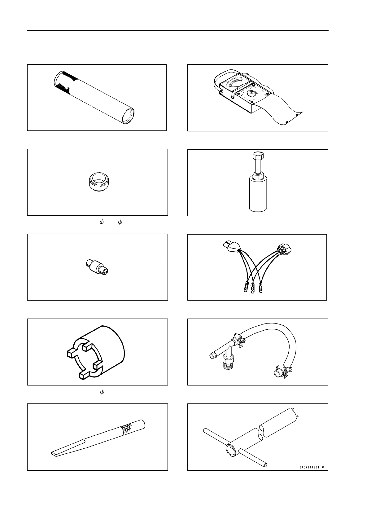
Oil P ressure Gauge, 5 kgf/cm²:
57001-125
Bearing Puller:
57001-135
Inside Circlip Pliers:
57001-143
Compression Gauge, 20 kgf/cm²:
57001-221
Valve Spring Compressor Assembly:
57001-241
Bearing Puller Adapter:
57001-317
Outside Circlip Pliers:
57001-144
Oil Pressure Gauge, 10 kgf/cm²:
57001-164
Bearing Driver:
57001-382
Piston Pin Puller Assembly:
57001-910
Page 33

Special Tools and Sealant
GENERAL INFORMATION 1-23
Oil Pressure Gauge Adapter, PT 1/8:
57001-1033
Oil Seal & Bearing Remover:
57001-1058
Head Pipe Outer Race Press Shaft:
57001-1075
Head Pipe Outer Race Remover:
57001-1107
Valve Seat Cutter, 45° - 35:
57001-1116
Valve Seat Cutter, 30° - 30:
57001-1120
Piston Ring Compressor Grip:
57001-1095
Steering Stem Nut Wrench:
57001-1100
Valve Seat Cutter, 32° - 35:
57001-1121
Valve Seat Cutter, 60° - 30:
57001-1123
Page 34

1-24 GENERAL INFORMATION
Special Tools a nd Sealant
Valve Seat Cutter Holder Bar:
57001-1128
Bearing Driver Set:
57001-1129
Valve Seat Cutter, 45° - 30:
57001-1187
Valve Guide Reamer, 5:
57001-1204
Valve Seat Cutter Holder, 5:
57001-1208
Rotor Puller, M16/M18/M20/M22 × 1.5:
57001-1216
Valve Spring Compressor Adapter, 22:
57001-1202
Valve Guide Arbor, 5:
57001-1203
Jack:
57001-1238
Clutch Holder:
57001-1243
Page 35

Special Tools and Sealant
GENERAL INFORMATION 1-25
Valve Seat Cutter, 55° - 35:
57001-1247
Oil Filter Wrench:
57001-1249
Carburetor Drain Plug Wrench, Hex 3:
57001-1269
Pilot Screw Adjuster, C:
57001-1292
Flywheel Holder:
57001-1313
Piston Ring Compressor Belt, 80 ∼ 91:
57001-1320
Fork Piston Rod Puller, M12 × 1.25:
57001-1289
Fork Oil Le vel Gauge:
57001-1290
Fork Oil Seal Driver, 43:
57001-1340
Flywheel & Pulley Holder:
57001-1343
Page 36
1-26 GENERAL INFORMATION
Special Tools a nd Sealant
Steering Stem Bearing Driver:
57001-1344
Steering Stem Bearing Driver Adapter:
57001-1345
Bearing Remover Head, 25 × 28:
57001-1346
Hand Tester:
57001-1394
Flywheel Puller Assembly, M38 × 1.5/M35 × 1.5:
57001-1405
Throttle Sensor Setting Adapter #2:
57001-1408
Socket Wrench:
57001-1370
Bearing Remover Shaft, 13:
57001-1377
Fuel Pressure Gauge Adapter:
57001-1417
Fork Cylinder Holder:
57001-1443
Page 37

Special Tools and Sealant
GENERAL INFORMATION 1-27
Head Pipe Outer Race Driver:
57001-1446
Head Pipe Outer Race Driver:
57001-1447
Lead Wire - Voltage Regulator Adapter:
57001-1448
Clutch Gear Setting Screw:
57001-1455
Needle Adapter Set:
57001-1457
Compression Gauge Adapter, M10 × 1.0:
57001-1458
Lead Wire - Peak Voltage Adapter:
57001-1449
Fork Spring Compressor Set:
57001-1452
Piston Base, 10:
57001-1459
Hook Wrench:
57001-1522
Page 38

1-28 GENERAL INFORMATION
Special Tools a nd Sealant
Throttle Sensor Setting Adapter:
57001-1538
Key Registration Unit:
57001-1582
Fork Spring Compressor:
57001-1587
Rotor Holder:
57001-1592
Kawasaki Bond (Silicone Sealant):
56019-120
Kawasaki Bond (Liquid Gasket - Black):
92104-1062
Pulley Holder, Grip:
57001-1591
Page 39

Cable, Wire, and Hose Routing (ZX1200-B1/B2)
GENERAL INFORMATION 1-29
Page 40

1-30 GENERAL INFORMATION
Cable, Wire, and Hose Routing (ZX1200-B1/B2)
Page 41

Cable, Wire, and Hose Routing (ZX1200-B1/B2)
GENERAL INFORMATION 1-31
Page 42

1-32 GENERAL INFORMATION
Cable, Wire, and Hose Routing (ZX1200-B1/B2)
Page 43

Cable, Wire, and Hose Routing (ZX1200-B1/B2)
GENERAL INFORMATION 1-33
Page 44

1-34 GENERAL INFORMATION
Cable, Wire, and Hose Routing (ZX1200-B1/B2)
Page 45

Cable, Wire, and Hose Routing (ZX1200-B1/B2)
GENERAL INFORMATION 1-35
Page 46

1-36 GENERAL INFORMATION
Cable, Wire, and Hose Routing (ZX1200-B1/B2)
Page 47

Cable, Wire, and Hose Routing (ZX1200-B1/B2)
GENERAL INFORMATION 1-37
Page 48

1-38 GENERAL INFORMATION
Cable, Wire, and Hose Routing (ZX1200-B1/B2)
Page 49

Cable, Wire, and Hose Routing (ZX1200-B1/B2)
GENERAL INFORMATION 1-39
Page 50

1-40 GENERAL INFORMATION
Cable, Wire, and Hose Routing (ZX1200-B1/B2)
Page 51

Cable, Wire, and Hose Routing (ZX1200-B1/B2)
GENERAL INFORMATION 1-41
Page 52

1-42 GENERAL INFORMATION
Cable, Wire, and Hose Routing (ZX1200-B1/B2)
Page 53
Cable, Wire, and Hose Routing (ZX1200-B1/B2)
GENERAL INFORMATION 1-43
Page 54

1-44 GENERAL INFORMATION
Cable, Wire, and Hose Routing (ZX1200-B1/B2)
Page 55

Cable, Wire, and Hose Routing (ZX1200-B1/B2)
GENERAL INFORMATION 1-45
Page 56

1-46 GENERAL INFORMATION
Cable, Wire, and Hose Routing (ZX1200-B3)
Page 57

Cable, Wire, and Hose Routing (ZX1200-B3)
1. Clamp
2. To Side Stand Switch
3. Insert the dampers of the ECU into the holes of the fender.
4. ECU
5. Atmospheric P ressure Sensor
6. Regulator/rectifier
7. From Regulator/rectifier
8. From Alternator
GENERAL INFORMATION 1-47
Page 58

1-48 GENERAL INFORMATION
Cable, Wire, and Hose Routing (ZX1200-B3)
Page 59

Cable, Wire, and Hose Routing (ZX1200-B3)
1. Front
2. About 45°
3. Viewed A
4. Clamp
GENERAL INFORMATION 1-49
Page 60

1-50 GENERAL INFORMATION
Cable, Wire, and Hose Routing (ZX1200-B3)
Page 61

GENERAL INFORMATION 1-51
Cable, Wire, and Hose Routing (ZX1200-B3)
1. Run the horn lead between the water hose and water pipe.
2. Clamp
3. Clamp the leads so that the speed sensor lead is outside.
4. Clamp the speed sensor lead, gear position switch lead and sub harness.
5. Section A-A
6. To Horn
7. Radiator Fan Switch
8. Clamp the horn lead and reserve tank hose.
9. Clamp the fan switch lead.
10. Clamp the side stand switch lead.
11. G ear Position Switch Lead
12. Speed Sensor Lead
13. Sub Harness
Page 62

1-52 GENERAL INFORMATION
Cable, Wire, and Hose Routing (ZX1200-B3)
Page 63

GENERAL INFORMATION 1-53
Cable, Wire, and Hose Routing (ZX1200-B3)
1. ECU Guard
2. Clamp
3. Connect the connectors of the fuel pump and fuel gauge leads.
4. To Alternator
5. Install the clamp with air cleaner cap.
6. Insert the harness into the clamps.
7. To Left Switch Housing
8. Immobilizer Antenna
9. Ignition Switch
10. Immobilizer Amplifier
11. View e d A
12. Crankshaft Sensor Lead
13. Engine
14. Right Lower Fairing
15. To R ight Switch Housing
16. To Battery Tray
17. Put the harness into the holes of the clamp.
18. To Rear Brake Light Switch
19. Put the harness into the holes of the fenders.
20. Right Turn S ignal Light Connector
21. Left Turn Signal Light Connector
22. Tail/Brake Light Connector
23. Right Turn Signal Light Lead
24. Diagnosis Connector
25. Self-diagnosis Indicator Terminal
26. Clamp (Fit the clamp to the rear frame.)
27. Atmospheric Pressure Sensor Connector
28. Viewed B
29. Trim (Fit the trim to the rear fender rear.)
Page 64

1-54 GENERAL INFORMATION
Cable, Wire, and Hose Routing (ZX1200-B3)
Page 65

GENERAL INFORMATION 1-55
Cable, Wire, and Hose Routing (ZX1200-B3)
1. To Meter Assembly
2. Sub Harness
3. Headlight Relays
4. Band (Clamp the ignition switch lead on to the upper bracket.)
5. Clamp (Bend inside the tip of the left side clamp.)
6. Left Side (Connect the left switch housing lead connectors and ignition switch lead connectors.)
Right Side (Connect the right switch housing connectors.)
7. Insert the clamp into the hole of the frame.
8. Clamp (Fit the clamp into the rear fender rear.)
9. Frame Ground (Install the ground with the air inlet pressure sensor bracket.)
10. Ignition Switch
11. To Left Switch Housing
12. Main Harness
Page 66

1-56 GENERAL INFORMATION
Cable, Wire, and Hose Routing (ZX1200-B3)
Page 67

Cable, Wire, and Hose Routing (ZX1200-B3)
1. Clamp the vacuum hose and fuel hose.
2. Vacuum Hose
3. Fuel Hose
4. Engine Sub Harness
5. Gear Position Switch Lead
6. Alternator Lead
7. Tube (Air Switching Valve – Canister):California Model Only
8. Clamp
9. Alternator Lead
10. Water Hose
11. View e d A
GENERAL INFORMATION 1-57
Page 68

1-58 GENERAL INFORMATION
Cable, Wire, and Hose Routing (ZX1200-B3)
Page 69

GENERAL INFORMATION 1-59
Cable, Wire, and Hose Routing (ZX1200-B3)
1. Air Switching Valve
2. Fan Leads
3. Run the water hose on the fan leads and fan switch lead.
4. Fan Relay (Signal) Connector
5. To Main Harness
6. Run the engine sub harness outside the lib of the head cover.
7. To Canister
8. Actuator
9. To Separator
10. Run the speed sensor lead back the bolt and under the gear position switch lead for prevention
of the lead lift up.
11. Speed Sensor
12. To Headlight Relay
13. Gear Position Switch Lead Connector
14. Engine Sub Harness Connector
15. Engine Sub Harness Connector
16. Run the starter motor cable under the engine sub harness.
17. Fix the crankshaft sensor lead connector.
18. Viewed A
19. Crankshaft Sensor Lead
20. Fuel Hose
21. Tube (Throttle Body – Separator): California Model Only
22. Alternator Lead
23. Run the alternator lead under the fuel tube.
Page 70

1-60 GENERAL INFORMATION
Unit Conversion Table
Prefixes for Units:
Prefix Symbol Power
mega M × 1 000 000
kilo k × 1 000
centi c ×0.01
milli m × 0.001
micro µ × 0.000001
Units of Mass:
kg × 2.205 = lb
g × 0.03527 = oz
Units of Volume:
L × 0.2642 = gal (US)
L × 0.2200 =
L × 1.057 =
L × 0.8799 = qt (imp)
L × 2.113 = pint (US)
L × 1.816 = pint (imp)
mL × 0.03381 = oz (US)
mL × 0.02816 = oz (imp)
mL × 0.06102 = cu in
gal (imp)
qt (US)
Units of Length:
km × 0.6214 = mile
m × 3.281 = ft
mm × 0.03937 = in
Units of Torque:
N·m × 0.1020 = kgf·m
N·m × 0.7376 = ft·lb
N·m × 8.851 = in·lb
kgf·m × 9.807 = N·m
kgf·m × 7.233 = ft·lb
kgf·m × 86.80 = in·lb
Units of Pressure:
kPa × 0.01020 = kgf/cm²
kPa × 0.1450 = psi
kPa × 0.7501 = cm Hg
kgf/cm² × 98.07 = kPa
kgf/cm² × 14.22 = psi
cmHg×1.333=kPa
Units of Speed:
km/h × 0.6214 = mph
Units of Force:
N × 0.1020 = kg
N × 0.2248 = lb
kg × 9.807 = N
kg × 2.205 = lb
Units of Temperature:
Units of Power:
kW ×1.360=PS
kW ×1.341=HP
PS × 0.7355 = kW
PS × 0.9863 = HP
Page 71

PERIODIC MAINTENANCE 2-1
Periodic Maintenance
Table of Contents
Periodic Maintenance Chart .............. 2-2
Specifications .................................... 2-4
Periodic Maintenance Procedures..... 2-6
Fuel System (DFI)........................... 2-6
Fuel Hose and Connection
Inspection .................................. 2-6
Throttle Control System
Inspection .................................. 2-7
Idle Speed Inspection .................. 2-8
Engine Vacuum Synchronization
Inspection .................................. 2-9
Air Cleaner Element Cleaning
(ZX1200-B1/B2)/Element
Replacement (ZX1200-B3) ....... 2-13
Evaporative Emission Control
System Inspection(CAL) ........... 2-14
Cooling System............................... 2-15
Cooling Hose and Connection
Inspection .................................. 2-15
Coolant Change........................... 2-15
Engine Top End .............................. 2-17
Air Suction Valve Inspection ........ 2-17
Valve Clearance Inspection ......... 2-18
Clutch.............................................. 2-22
Clutch Adjust Inspection .............. 2-22
Engine Lubrication System............. 2-23
Engine Oil Change....................... 2-23
Oil Filter Replace ......................... 2-23
Wheels/Tires................................... 2-24
Tire Wear Inspection .................... 2-24
Final Drive....................................... 2-25
Drive Chain Slack Inspection....... 2-25
Drive Chain Wear Inspection ....... 2-26
2
Drive Chain Lubrication................ 2-28
Brakes............................................. 2-28
Brake Hose, Connection
Inspection.................................. 2-28
Brake Fluid Level Inspection........ 2-29
Brake Fluid Change ..................... 2-29
Front Brake Pad Wear Inspection 2-30
Rear Brake Pad Wear Inspection 2-31
Brake/Master Cylinder Cup and
Dust Seal Replace .................... 2-31
Caliper Piston/Dust Seal Replace 2-31
Front Brake Light Switch
Inspection.................................. 2-31
Rear Brake Light Switch
Inspection/Adjustment............... 2-31
Suspension..................................... 2-32
Front Fork Oil Change ................. 2-32
Front Fork Oil Leak Inspection..... 2-42
Rear Shock Absorber Oil Leak
Inspection.................................. 2-42
Swingarm Pivot Lubrication ......... 2-42
Unit-trak Linkage Lubrication ....... 2-43
Steering .......................................... 2-43
Steering Inspection ...................... 2-43
Steering Stem Bearing
Lubrication................................. 2-45
Electrical System ............................ 2-45
Spark Plug Cleaning and
Inspection.................................. 2-45
General Lubrication ........................ 2-45
Lubrication Perform...................... 2-45
Nut, Bolt, and Fastener Tightness .. 2-47
Tightness Inspection .................... 2-47
Page 72

2-2 PERIODIC MAINTENANCE
Periodic Maintenance Chart
The scheduled maintenance must be done in accordance with this chart to keep the motorcycle in
good running condition. The initial maintenance is vitally important and must not be neglected.
FREQUENCY Whichever
comes
first
1 6 12 18 24 30 36
OPERATION Every (0.6) (4) (7.5) (12) (15) (20) (24)
Steering - inspect †
Steering stem bearing - lubricate
Brake hoses, connections - inspect †
Brake fluid level - inspect † month
Brake fluid - change 2 years
Brake pad wear - inspect † #
Brake master cylinder cup and dust seal
-replace
Caliper piston seal and dust seal - replace 4 years 2-31
Brake light switches - inspect †
Tire wear - inspect †
Front fork oil - change
Front fork oil leak - inspect †
Rear shock absorber oil leak - inspect †
Swingarm pivot, Unit-track linkage lubricate
2 years
4 years 2-31
2 years
• • • • • • •
• • • • • •
• • • • • • •
• • • • • •
• • • • • • •
• • • • • •
• • •
• • •
• • •
*Odometer Reading
× 1000 km
(× 1000 mile)
Refer-
ence
2-43
•
•
•
2-45
2-28
2-29
2-29
2-30
2-31
2-24
2-32
2-42
2-42
2-42
Clutch adjust - inspect †
Drive chain slack - inspect † # 1 000 km 2-25
Drive chain wear - inspect † #
Drive chain roller wear - inspect † #
Drive chain - lubricate # 600 km 2-28
Spark plug (e) - clean and gap †
Fuel hoses, connections - inspect †
Throttle control system (e) - inspect †
Idle speed (e) - inspect †
Engine vacuum sychronization (e) inspect †
Air cleaner element (e) - clean † #
(ZX1200-B1/B2)
Air cleaner element (e) - replace † #
(ZX1200-B3)
Evaporative emission control system (e)
(CAL) - inspect †
Air suction valve (e) - inspect †
Valve clearance (e) - inspect †
Cooling hoses, connections - inspect †
Coolant - change 2 years
• • • • • • •
• • • • • •
• • • • • •
• • • • • •
• • • • • •
• • • • • • •
• • • •
• • •
• • •
•
• • • • • • •
• • • • • •
• • •
•
•
2-22
2-26
2-27
2-45
2-6
2-7
2-8
2-9
2-13
2-13
2-14
2-17
2-18
2-15
2-15
Page 73

Periodic Maintenance Chart
PERIODIC MAINTENANCE 2-3
FREQUENCY Whichever
comes
first
1 6 12 18 24 30 36
OPERATION Every (0.6) (4) (7.5) (12) (15) (20) (24)
Engine oil - change # 6 months
Oil filter - replace
General lubrication - perform
Nuts, bolts, and fasteners tightness inspect †
#: Service more frequently when operating in severe conditions; dusty, wet, muddy, high speed,
or frequent starting/stopping.
*: For higher odometer readings, repeat at the frequency interval established here.
†: Replace, add, adjust, clean, or torque if necessary.
CAL: California model only
e: Emission Related Items
• • • • • • •
• • • •
• • •
• • • •
*Odometer Reading
× 1000 km
(× 1000 mile)
Refer-
ence
2-23
2-23
2-45
2-47
Page 74

2-4 PERIODIC MAINTENANCE
Specifications
Item Standard Service Limit
Fuel System (DFI)
Throttle Grip Free Play 2 ∼ 3 mm (0.08 ∼ 0.12 in.) –––
Idle Speed 1 000 ±50 r/min (rpm) –––
Throttle Body Vacuum 26 ±1.333 kPa (195 ±10 mmHg) –––
Air Cleaner Element:
ZX1200-B1/B2 Polyurethane foam –––
ZX1200-B3 Filter paper –––
Air Cleaner Element Oil SE, SF or SG SAE 30, or High-quality air
filter oil
Cooling System
Coolant:
Type (Recommended) Permanent type antifreeze –––
Color Green –––
Mixed Ratio Soft water 50%, Coolant 50% –––
Freezing Point – 35°C (– 31°F) –––
Total Amount 3.6L(3.8USqt) –––
Engine Top End
Valve Clearance:
Exhaust 0.22 ∼ 0.31 mm (0.0087 ∼ 0.0122 in.) –––
Inlet 0.15 ∼ 0.24 mm (0.0059 ∼ 0.0094 in.) –––
Clutch
Clutch Lever Free Play 2 ∼ 3 mm (0.08 ∼ 0.12 in.) –––
Engine Lubrication System
Engine Oil:
Type API SE, SF or SG –––
API SH or SJ with JASO MA
Viscosity SAE 10W-40 –––
Capacity 2.5 L (2.6 US qt, when filter is not removed) –––
2.8 L (3.0 US qt, when filter is removed) –––
3.6 L (3.8 US qt, when engine is completely
disassembled and dry)
Level
Tires
Tread Depth:
Front: DUNLOP D208FJ 4.0 mm (0.16 in.) 1 mm (0.04 in.)
Rear: DUNLOP D208J 5.4 mm (0.21 in.) 2 mm (0.08 in.)
Between upper and lower level lines (after
idling or running)
1.6 mm (0.063 in.)
–––
–––
–––
(AT, CH, DE):
Up to 130 km/h
(80 mph)
Over 130 km/h
(80 mph)
3 mm (0.12 in.)
Page 75

PERIODIC MAINTENANCE 2-5
Specifications
Item Standard Service Limit
Air Pressure: (when Cold)
Front Up to 182 kg (401 lb) l oad: –––
290 kPa (2.9 kgf/cm², 42 psi)
Rear Up to 182 kg (401 lb) load: –––
290 kPa (2.9 kgf/cm², 42 psi)
Final Drive
DriveChainSlack 25 ∼ 35 mm (0.98 ∼ 1.4 in.) –––
Drive Chain Roller Distance Less than 6 mm (0.236 in.) 6.2 mm (0.244 in.)
Drive Chain 20-link Length 317.5 ∼ 318.2 mm (12.50 ∼ 12.53 in.) 323 mm (12.7 in.)
Brakes
Brake Fuid:
Grade DOT4 –––
Brake Pad Lining Thickness:
Front and Rear 4 mm (0.12 in.) 1 mm (0.04 in.)
Brake Light Timing:
Front Pulled ON –––
Rear ON after about 10 mm (0.39 in.) of pedal
travel
Suspension
Fork Oil:
Viscosity KAYABA KHL15-10 (SAE 0 W) –––
Amount (per Side):
When Changing Oil approx. 420 mL (14.2 US oz) –––
After Disassembly and
490 ±4 mL (16.6 ±0.1 US oz) –––
Completely Dry
Fork Oil Level: 93 ±2 mm (3.66 ±0.08 in.)
(Fully Compressed, without
(from the top of the outer tube)
Spring)
Electrical System
Spark Plug Gap 0.7 ∼ 0.9 mm (0.028 ∼ 0.035 in.) –––
–––
–––
AT: Republic of Austria
CH: Swiss Confederation
DE: Federal Republic of Germany
Special Tools - Steering Stem Nut Wrench: 57001-1100
Jack: 57001-1238
Oil Filter Wrench: 57001-1249
Fork Piston Rod Puller, M12 × 1.25: 57001-1289
Fork Oil Level Gauge: 57001-1290
Pilot Screws Adjuster, C: 57001-1292
Fork Spring Compressor Set: 57001-1452
Fork Spring Compressor: 57001-1587
Page 76
2-6 PERIODIC MAINTENANCE
Periodic Maintenance Procedures
Fuel System (DFI)
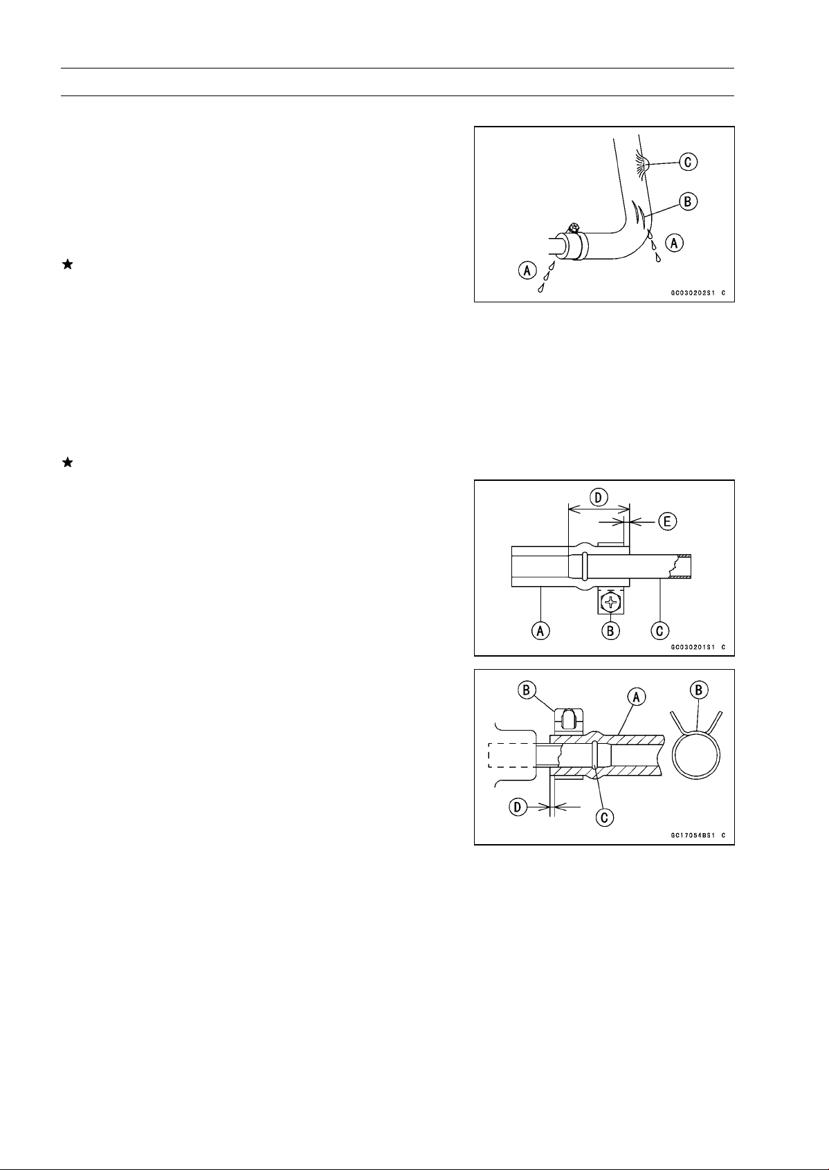
Fuel Hose and Connection Inspection
The fuel hoses are designed to be used throughout the
○
motorcycle’s life without any maintenance, however, if the
motorcycle is not properly handled, the high pressure inside the fuel line can cause fuel to leak [A] or the hose
to burst. Remove the fuel tank (see Fuel System (DFI)
chapter) and check the fuel hose.
Replace the fuel hose if any fraying, cracks [B] or bulges
[C] are noticed.
Check that the hoses are securely connected and clamps
•
are tightened correctly.
When installing, route the hoses according to Cable,
•
Wire, and Hose Routing section in the General Information chapter.
When installing the fuel hoses, avoid sharp bending, kink-
•
ing, flattening or twisting, and route the fuel hoses with a
minimum of bending so that the fuel flow will not be obstructed.
Replace the hose if it has been sharply bent or kinked.
Install the hose clamps in the position shown, and se-
•
curely tighten the clamp screws to the specified torque.
Check the fuel system for leaks after hose installation.
Fuel Hose [A ]
Clamp [B]
Fuel Pipe [C]
18 ∼ 22 mm (0.70 ∼ 0.87 in.) [D]
2 ∼ 3 mm (0.08 ∼ 0.12 in.) [E]
Fit the fuel hose [A] onto the pipe fully and install the plate
•
clamp [B] beyond the raised rib [C].
1 ∼ 2 mm (0.04 ∼ 0.08 in.)
Page 77

Periodic Maintenance Procedures
Throttle Control System Inspection
Check the throttle grip free play [B].
•
If the free play is incorrect, adjust the throttle cables.
Throttle Grip Free Play
Standard: 2 ∼ 3 mm (0.08 ∼ 0.12 in.)
Check that the throttle grip [A] moves smoothly from full
•
open to close, and the throttle closes quickly and completely in all steering position by the return spring.
If the throttle grip does not return properly, check the throttle cables routing, grip free play, and cable damage. Then
lubricate the throttle cable.
Run the engine at the idle speed, and turn the handlebar
•
all the way to the right and left to ensure that the idle speed
does not change.
If the idle speed increase, check the throttle cable free
play and the cables routing.
Remove the right lower inner cover (see Frame chapter).
•
Loosen the locknuts.
•
Screw both throttle cable adjuster to give the throttle grip
•
plenty of play.
Completely close the throttle grip, turn the accelerator
•
cable adjuster [A] to eliminate any cable free play, and
tighten the adjuster locknut [B].
Turn the decelerator cable adjuster [C] to adjust the throt-
•
tlegripfreepalyto2∼ 3 mm (0.08 ∼ 0.12 in.).
Tighten the deaccelerator cable locknut [D] securely.
•
If the free paly cannot be adjusted with the adjusters, replace the cable.
ZX1200-B1/B2 [E]
ZX1200-B3 [F]
PERIODIC MAINTENANCE 2-7
Check the throttle bore for cleanliness as follows:
•
Set up the fuel tank (see Fuel System (DFI) chapter).
○
Disconnect the inlet air temperature sensor connector [A].
○
Remove:
○
Air Cleaner Cap Bolts [B]
Right and Left Air Cleaner Caps [C]
Page 78

2-8 PERIODIC MAINTENANCE
Periodic Maintenance Procedures
In accordance with the Periodic Maintenance Chart,
○
check the throttle bores [A] at the butterfly valves [B] and
around them for carbon deposits by opening the valves.
If any carbon accumulates, wipe the carbon off the throttle
bores around the butterfly valves, using a lint-free cloth
[C] penetrated with high-flash point solvent.
Idle Speed Inspection
Start the engine and warm it up thoroughly.
•
With the engine idling, turn the handlebar to both sides
•
[A].
If handlebar movement changes the idle speed, the
throttle cables may be improperly adjusted or incorrectly
routed, or damaged. Be sure to correct any of these
conditions before riding (see Cable Routing Section in
General Information chapter).
WARNING
Operation with improperly adjusted, incorrectly
routed, or damaged cables could result in an unsafe riding condition.
Check the idle speed.
•
If the idle speed is out of specified range, adjust it.
Idle Speed
Standard: 1 000 ±50 r/min (rpm)
Start the engine and warm it up thoroughly.
•
Turn the adjusting screw [A] until the idle speed is correct.
•
Open and close the throttle a few times to make sure that
○
the idle speed is within the specified range. Readjust if
necessary.
ZX1200-B1/B2 [B]
ZX1200-B3 [C]
Page 79

Periodic Maintenance Procedures
Engine Vacuum Synchronization Inspection
ZX1200-B1/B2
NOTE
These procedures are explained on the assumption that
○
the inlet and exhaust system of the engine are in good
condition.
Remove the lower inner covers (see Frame chapter).
•
Set up the fuel tank (see Fuel System (DFI) chapter).
•
Pull out the vacuum switch valve hose [B] from the air
•
cleaner.
Pull off the three vacuum hoses [A] and rubber cap from
•
the right fittings on the throttle bodies.
CAUTION
Do not remove the atmospheric pressure hose.
Completely close the removed hoses [A] and [B] of the
•
clean air system with the proper plugs.
Completely close the clean air system hole of the air
•
cleaner with the proper plug.
PERIODIC MAINTENANCE 2-9
Start the engine and warm it up thoroughly.
•
Check the engine speed, using the engine revolution
•
tester [A] for high accuracy.
If the engine speed is out of 1 000 rpm, set the engine
speed to
1 000 rpm.
CAUTION
Do not adjust the engine speed by the tachometer
in the meter unit.
Connect the vacuum gauge hoses [A] to the right fittings
•
on the throttle bodies.
Connect the vacuum gauge hoses to the vacuum gauge
•
[B].
Start the engine and left it idle to measure the inlet vac-
•
uum.
If the vacuum is incorrect, adjust the synchronization.
Engine Vacuum
Standard: 26 ±1.333 kPa (195 ±10 mmHg) at Idle
Speed 1 000 ±50 r/min (rpm)
Page 80

2-10 PERIODIC MAINTENANCE
Periodic Maintenance Procedures
Turn the adjusting screw [A] to synchronize the throttle
•
valves.
First synchronize the left two or the right two throttle
○
valves by means of the left and right adjusting screws.
Then synchronize the left two throttle valves and the right
two throttle valves using the center adjusting screw.
If the throttle valves synchronization cannot be obtained
by using the adjusting screws, check for dirt or blockage,
and then check the inlet parts connection.
Special Tool - Pilot Screw Adjuster, C: 57001-1292 [B]
Check the throttle valve synchronization again
•
NOTE
Do not turn the bypass screws [A] carelessly during
○
throttle valve synchronization. You may cause poor running at low engine speed or irregular throttle sensor output voltage.
Remove the vacuum gauge hoses and install the re-
•
moved parts.
Check the idle speed.
•
ZX1200-B3
NOTE
These procedures are explained on the assumption that
○
the inlet and exhaust systems of the engine are in good
condition.
Situate the motorcycle so that it is vertical.
•
Remove the lower inner covers (see Frame chapter).
•
Set up the fuel tank (see Fuel System (DFI) chapter).
•
Pull off the vacuum hoses [A] and rubber cap(s) from the
•
right fittings of each throttle body.
Pull off the air switching valve hose [B] from the air cleaner
•
housing.
CAUTION
Do not remove the atmospheric pressure hose.
Plug:
•
Air Switching Valve Hose [A] and its Air Cleaner H ousing
Hole
Page 81

Periodic Maintenance Procedures
Start the engine and warm it up thoroughly.
•
Check the idle speed.
•
Tachometer [A]
Open and close the throttle.
•
If the idle speed is out of the specified range, adjust it.
CAUTION
Do not measure the idle speed by the tachometer of
the meter unit.
Connect a commercially available vacuum gauge [A] to
•
these right fittings of the throttle body.
While idling the engine, inspect the engine vacuum, using
•
the vacuum gauge.
Engine Vacuum
Standard: 26 ±1.333 kPa (195 ±10 mmHg) at Idle
Speed 1 000 ±50 r/min (rpm)
PERIODIC MAINTENANCE 2-11
If any vacuum is not within the specifications, first synchronize the balance of the left (#1, #2) and right (#3, #4)
assemblies.
Example:
#1: 165 mmHg
#2: 190 mmHg
#3: 170 mmHg
#4: 200 mmHg
With the engine at the correct idle speed, equalize the
•
lower vacuum of #1 and #2 (example 165 mmHg) to the
lower vacuum of #3 and #4 (example 170 mmHg) by turning the center adjusting screw [A].
Special Tool - Pilot Screw Adjuster, C: 57001-1292
Front [B]
NOTE
After adjustment, the final vacuum m easurement be-
○
tween the lowest throttle valves may not be 165 mmHg
(in this example). The goal is to have the lower two
vacuums between the left (1 and 2) and right (3 and 4)
banks be the same.
Open and close the throttle after each measurement and
•
adjust the idle speed as necessary.
Once the throttle valves have been synchronized, inspect
•
the main throttle sensor’s output voltage to ensure proper
operation (procedure is at the end of this section).
Page 82

2-12 PERIODIC MAINTENANCE
Periodic Maintenance Procedures
If any one vacuum measurement is out of the standard
measurement after left and right synchronization, turn in
the bypass screw [A] until it seat fully but not tightly.
CAUTION
Do not over tighten them. They could be damaged,
requiring replacement.
Turn out the bypass screw of the higher vacuum between
•
#1 and #2 to the lower vacuum.
Turn out the bypass screw of the higher vacuum between
•
#3 and #4 to the lower vacuum.
Open and close the throttle valves after each measure-
•
ment and adjust the idle speed as necessary.
Inspect the vacuums as before.
•
If all vacuums are within the specification, finish the engine vacuum synchronization.
If any vacuum can not be adjusted within the specification,
remove the bypass screws #1 ∼ #4 and clean them.
Remove the bypass screw [A], spring [B], washer [C] and
•
O-ring [D].
Check the bypass screw and its hole for carbon deposits.
○
If any carbon accumulates, wipe the carbon off the bypass
screw and the hole, using a cotton pad penetrated with a
high-flash point solvent.
Replace the O-ring with a new one.
○
Check the tapered portion [E] of the bypass screw for
○
wear or damage.
If the bypass screw is worn or damaged, replace it.
Turn in the bypass screw until it seats fully but not tightly.
•
Repeat the same procedure for other bypass screws.
•
Repeat the synchronization.
•
If the vacuums are correct, check the output voltage of
the main throttle sensor (see Output Voltage Inspection of
Main Throttle Sensor in the Fuel System (DFI) chapter).
Main Throttle Sensor Output Voltage
Connections to ECU
Meter (+) → Y/W lead (terminal 7)
Meter (–) → BR/BK lead (terminal 2 8)
Standard:
1.06 ∼ 1.10 V DC (at idle throttle opening)
If the output voltage is out of the range, check the throttle
input voltage (see Input Voltage Inspection of Main Throttle Sensor in the Fuel System (DFI) chapter).
Remove the vacuum gauge hoses and install the vacuum
•
hoses and rubber caps on the original position as shown.
Page 83

Periodic Maintenance Procedures
Air Cleaner Element Cleaning (ZX1200-B1/B2)/
Element Replacement (ZX1200-B3)
NOTE
In dusty areas, the element should be cleaned more
○
frequently than the recommended interval.
After riding through rain or on muddily roads, the ele-
○
ment should be cleaned immediately.
WARNING
If dirt or dust is allowed to pass through into the
throttle assy, the throttle may become stuck, possibly causing accident.
CAUTION
If dirt gets through into the engine, excessive engine wear and possibly engine damage will occur.
WARNING
PERIODIC MAINTENANCE 2-13
Clean the element in a well-ventilated area, and take
care that there are no sparks or flame anywhere
near the working area; this includes any appliance
with a pilot light.
Because of the danger of highly flammable liquids,
do not use gasoline or a low flash-point solvent to
clean the element.
Remove:
•
Seats (see Frame chapter)
Fuel Tank Cover (see Fuel Tank Removal section in Fuel
System (DFI) chapter)
Set up t he fuel tank [A] with the supporting rod [B].
•
CAUTION
Do not insert the supporting rod into the bolt hole,
or the thread of the bolt hole could be damaged.
Unscrew the nuts [A] and remove the bolts.
•
Pull out the elements [B].
•
Page 84

2-14 PERIODIC MAINTENANCE
Periodic Maintenance Procedures
ZX1200-B1/B2
Clean the element [A] in cleaning solvent, and then dry it
•
with compressed air or by shaking it.
After cleaning, saturate a clean, lint-free towel with SE,
•
SF, SG class SAE-30 oil or high-quality air filter oil, and
apply the oil to the element by tapping the element outside
with the towel.
Inspect the element before installing it.
•
If the element is broken, or the frame is damaged or bent,
replace the element.
ZX1200-B3
Discard the air cleaner elements.
•
Air Cleaner Elements [A]
Install the elements [A] with the mark side (FRONT) facing
•
front.
Evaporative Emission Control System Inspection (CAL)
Inspect the canister as follows.
•
Remove:
○
Seats (see Frame chapter)
Storage Box (see Frame chapter)
Remove the canister [A], and disconnect the hoses from
○
the canister.
Visually inspect the canister for cracks and other damage.
○
If the canister has any cracks or bad damage, replace it
with a new one.
NOTE
The canister is designed to work well through the motor-
○
cycle’s life without any maintenance if it is used under
normal conditions.
Page 85

Periodic Maintenance Procedures
Check the liquid/vapor separator as follows:
•
Remove:
○
Seat (see Frame chapter)
Fuel Tank Cover (see Fuel Tank Removal section in Fuel
System (DFI) chapter)
Supporting Rod (see Fuel Tank R emoval section in Fuel
System (DFI) chapter)
Disconnect the hoses from the separator, and remove the
○
separator [A] from the motorcycle right side.
Visually inspect the separator for cracks and other dam-
○
age.
If the separator has any cracks or damage, replace it with
a new one.
To prevent the gasoline from flowing into or out of the
○
canister, hold t he separator perpendicular to the ground.
Check the hoses of the evaporative emission control sys-
•
tem as follows:
Check that the hoses are securely connected and clips
○
are in position.
Replace any kinked, deteriorated or damaged hoses.
○
Route the hoses according to Cable, Wire, and Hose
○
Routing section in the General Information chapter. Refer
to the diagram of the evaporative emission control system
in the Fuel System (DFI) chapter too.
When installing the hoses, avoid sharp bending, kinking,
○
flattening or twisting, and route the hoses with a minimum
of bending so that the emission flow will not be obstructed.
PERIODIC MAINTENANCE 2-15
Cooling System
Cooling Hose and Connection Inspection
The high pressure inside the cooling hose can cause
○
coolant to leak [A] or the hose to burst if the line is not
properly m aintained. Visually inspect the hoses for signs
of deterioration. Squeeze the hoses. A hose should not
be hard and brittle, nor should it be soft or swollen.
Replace the hose if any fraying, cracks [B] or bulges [C]
are noticed.
Check that the hoses are securely c onnected and clamps
•
are tightened correctly.
Torque - Cooling Hose Clamp Screws: 2.0 N·m (0.20 kgf·m,
18 in·lb)
Coolant Change
WARNING
To avoid burns, do not remove the radiator cap or
try to change the coolant when the engine is still
hot. Wait until it cools down. Coolant on tires will
make them slippery and can cause an accident
and injury. Immediately wipe up or wash away any
coolant that spills on the frame, engine, or other
painted parts.
Since coolant is harmful to the human body, do not
use for drinking.
Page 86

2-16 PERIODIC MAINTENANCE
Periodic Maintenance Procedures
Remove:
•
Right Lower Inner Cover (see Frame chapter)
Right Air Inlet Duct (see Fuel System (DFI) chapter)
Radiator Cap [A]
Remove the radiator cap in two steps. First turn the cap
○
counterclockwise to the first stop. Then push and turn it
further in the same direction and remove the cap.
Remove:
•
Left Lower Fairing (see Frame chapter)
Place a containers under the drain plugs [A] and [B] at the
•
bottom of the water pump cover and cylinder.
Drain the coolant from the radiator and engine by remov-
•
ing the drain plugs.
Remove:
•
Mounting Screws [A] and Reserve Tank [B]
Hose [C]
Remove the cap [D] and pour the coolant into a container.
•
Install the reserve tank.
•
Tighten the drain plugs with the washers.
•
Replace the drain plug gasket with new one if it is dam-
○
aged.
Torque - Coolant D rain Plug (Water Pump): 12 N·m (1.2
kgf·m, 106 in·lb)
Coolant Drain Plug (Cylinder): 10 N·m (1.0 kgf·m,
89 in·lb)
Fill the r adiator up to the radiator filler neck [A] with
•
coolant, and install the radiator cap.
NOTE
Pour in the coolant slowly so that it can expel the air
○
from the engine and radiator.
Fill the reserve tank up to the full level line with coolant,
•
and install the cap.
CAUTION
Soft or distilled water must be used with the antifreeze (see below for antifreeze) in the cooling system.
If hard water is used in the system, it causes scales
accumulation in the water passages, and considerably reduces the efficiency of the cooling system.
Page 87

Periodic Maintenance Procedures
Water and Coolant Mixture Ratio (Recommended)
Soft Water: 50%
Coolant: 50%
Freezing Point: – 35°C (– 31°F)
Total Amount: 3.6 L (3.8 US qt)
NOTE
Choose a suitable mixture ratio by referring to the
○
coolant manufacturer’s directions.
Bleed the air from the cooling system as follows.
•
Start the engine with the radiator cap removed and run it
○
until no more air bubbles [A] can be seen in the coolant.
Tap the radiator hoses to force any air bubbles caught
○
inside.
Stop the engine and add coolant up to the radiator filler
○
neck.
Install the radiator cap.
•
Start the engine, warm it up thoroughly until the radiator
•
fan turns on and then stop the engine.
Check the coolant level in the reserve tank after the en-
•
gine cools down.
If the coolant level is lower than the low level line, add
coolant to the full level line.
PERIODIC MAINTENANCE 2-17
CAUTION
Do not add more coolant above the full level line.
Engine Top E nd
Air Suction Valve Inspection
Remove the air suction valve (see Air Suction Valve Re-
•
moval section in Engine Top End chapter).
ZX1200-B1/B2 [A]
ZX1200-B3 [B]
Visually inspect the reeds [C] for cracks, folds, warps,
•
heat damage, or other damage.
If there is any doubt as to the condition of the reed, replace
the air suction valve as an assembly.
Check the reed contact areas [D] of the valve holder
•
for grooves, scratches, any signs of separation from the
holder, or heat damage.
If there is any doubt as to the condition of the reed contact
areas, replace the air suction valve as an assembly.
If any carbon or other foreign particles have accumulated
between the reed and the reed contact area, wash the
valve assembly with a high flash-point solvent.
CAUTION
Do not scrape off the deposits with a scraper as this
could damage the rubber, requiring replacement of
the suction valve assembly.
Page 88

2-18 PERIODIC MAINTENANCE
Periodic Maintenance Procedures
Valve Clearance Inspection
NOTE
Valve clearance must be checked and adjusted when
○
the engine is cold (at room temperature).
Remove:
•
Lower Fairings with Lower Inner Fairing (see Frame
chapter)
Crankshaft Sensor Cover (see Electrical System chapter)
Cylinder Head Cover (see Cylinder Head Cover Removal section in Engine Top End chapter)
Position the crankshaft at #1, #4 piston TDC.
•
TDC Mark [A] for #1, #4 Pistons
Timing Mark [B] (crankcase halves mating surface)
If just after the camshaft cap is installed, rotate the crankshaft two turns in the right direction.
Measure the valve clearance between the cam and the
•
valve lifter with a thickness gauge [A].
Valve Clearance
Standard:
Exhaust
Inlet
When positioning #4 piston TDC at the end of the
○
compression stroke:
Inlet valve clearance of #2 and #4 cylinders
Exhaust valve clearance of #3 and #4 cylinders
When positioning #1 piston TDC at the end of the
○
compression stroke:
Inlet valve clearance of #1 and #3 cylinders
Exhaust valve clearance of #1 and #2 cylinders
0.22 ∼ 0.31 mm (0.0087 ∼ 0.0122 in.)
0.15 ∼ 0.24 mm (0.0059 ∼ 0.0094 in.)
If the valve clearance is not within the specified range,
first record the clearance, and then adjust it.
Page 89

Periodic Maintenance Procedures
To change the valve clearance, remove the camshaft
•
chain tensioner, camshafts and valve lifters. Replace the
shim with one of a different thickness.
NOTE
Mark and record the valve lifter and shim locations so
○
they can be reinstalled in their original positions.
If there is no clearance, select a shim which is several
○
sizes smaller and then measure the clearance.
To select a new shim which brings the valve clearance
•
within the specified range, refer to the Valve Clearance
Adjustment Charts.
Apply molybdenum disulfide oil to the valve lifters and ap-
•
ply engine oil to the shims.
Install the camshafts. Be sure to time the camshafts prop-
•
erly (see Camshaft Installation).
Remeasure any valve clearance that was adjusted.
○
Readjust if necessary.
CAUTION
PERIODIC MAINTENANCE 2-19
Do not put shim stock under the shim. This may
cause the shim to pop out at high rpm, causing extensive engine damage.
Do not grind the shim. This may cause it to fracture,
causing extensive engine damage.
Page 90

2-20 PERIODIC MAINTENANCE
Periodic Maintenance Procedures
INLET VALVE CLEARANCE ADJUSTMENT CHART
1. Measure the clearance (when engine is cold).
2. Check present shim size.
3. Match clearance in vertical column with present shim
size in horizontal column.
4. Install the shim specified where t he lines intersect.
This shim will give the proper clearance.
Example:
Present shim is 2.60 mm.
Measured clearance is 0.35 mm.
Replace 2.60 mm shim with 2.75 mm shim.
5. Remeasure the valve clearance and readjust if necessary.
Page 91

PERIODIC MAINTENANCE 2-21
Periodic Maintenance Procedures
EXHAUST VALVE CLEARANCE ADJUSTMENT CHART
1. Measure the clearance (when engine is cold).
2. Check present shim size.
3. Match clearance in vertical column with present shim
size in horizontal column.
4. Install the shim specified where the lines intersect.
This shim will give the proper clearance.
Example:
Present shim is 2.65 mm.
Measured clearance is 0.42 mm.
Replace 2.65 mm shim with 2.80 mm shim.
5. Remeasure the valve clearance and readjust if necessary.
Page 92

2-22 PERIODIC MAINTENANCE
Periodic Maintenance Procedures
Clutch
Clutch Adjust Inspection
Pull the clutch lever just enough to take up the free play
•
[A].
Measure the gap between the lever and the lever holder.
•
If the gap is too wide, the clutch may not release fully. If
the gap is too narrow, the clutch may not engage fully. In
either case, adjust it.
Clutch Lever Free Play
Standard: 2 ∼ 3 mm (0.08 ∼ 0.12 in.)
WARNING
To avoid a serious burn, never touch the engine or
muffler during clutch adjustment.
Turn the adjuster [A] so that 5 ∼ 6 mm (0.20 ∼ 0.24 in.) [B]
•
of threads are visible.
Slide the dust cover [A] at the clutch cable lower end out
•
of place.
Loosen both adjusting nuts [B] at the clutch cover as far
•
as they will go.
Pull the clutch outer cable [C] tight and tighten the adjust-
•
ing nuts against the bracket [D].
Slip the rubber dust cover back onto place.
•
Turn the adjuster at the clutch lever until the free play is
•
correct.
Push the release lever [A] toward the front of the motor-
•
cycle until it becomes hard to turn.
At this time, the release lever should have the proper an-
○
gle shown.
If the angle is wrong, check the clutch and release parts
for wear.
WARNING
Be sure that the outer cable end at the clutch lever
is fully seated in the adjuster at the clutch lever, or
it could slip into place later, creating enough cable
play to prevent clutch disengagement.
After the adjustment, start the engine and check that the
•
clutch does not slip and that it releases properly.
Page 93

Periodic Maintenance Procedures
Engine Lubrication System
Engine Oil Change
Support the motorcycle perpendicular to the ground after
•
warming up the engine.
Remove the engine oil drain plug [A] to drain the oil.
•
The oil in the oil filter can be drained by removing the filter
○
(see Oil Filter Change).
Replace the drain plug gasket with a new one if it is dam-
○
aged.
Tighten the drain plug.
•
Torque - Engine Oil Drain Plug: 20 N·m (2.0 kgf·m, 15 ft·lb)
Pour in the specified type and amount of oil.
•
Engine Oil
Grade: API SE, SF or SG
API SH or SJ with JASO MA
Viscosity:
Amount:
SAE 10W-40
2.5 L (2.6 US qt, when filter is not removed)
2.8 L (3.0 US qt, when filter is removed)
3.6 L (3.8 US qt, when engine is completely
dry)
PERIODIC MAINTENANCE 2-23
NOTE
Although 10W-40 engine oil is the recommended oil
○
for most conditions, the oil viscosity may need to be
changed to accommodate atmospheric conditions in
your riding area.
Oil Filter Replace
Drain the engine oil (see Engine Oil Change).
•
Remove:
•
Lower Inner Fairing (see Frame chapter)
Remove the oil filter [B] with the oil filter wrench [A].
•
Special Tool - Oil Filter Wrench: 57001-1249
Replace the filter with a new one.
•
Apply engine oil to the gasket [A] before installation.
•
Tighten the filter with the oil filter wrench.
•
Torque - Oil Filter: 31 N·m (3.2 kgf·m, 23 ft·lb)
Pour in the specified type and amount of oil (see Engine
•
Oil Change).
Page 94

2-24 PERIODIC MAINTENANCE
Periodic Maintenance Procedures
Wheels/Tires
Tire Wear Inspection
As the tire tread wears down, the tire becomes more susceptible to puncture and failure. An accepted estimate is
that 90% of all tire failures occur during the last 10% of tread
life (90% worn). So it is false economy and unsafe to use
the tires until they are bald.
Remove any imbedded stones or other foreign particles
•
from the tread.
Visually inspect the tire for cracks and cuts, replacing the
•
tire in case of damage. Swelling or high spots indicate
internal damage, requiring tire replacement.
Measure the tread depth at the center of the tread with
•
a depth gage [A]. Since the tire may wear unevenly, take
measurement at several places.
If any measurement is less than the service limit, replace
the tire.
Tread Depth
Front:
Standard: 4.0 mm (0.16 in.) (DUNLOP)
Service Limit: 1 mm (0.04 in.)
(AT, CH, DE) 1.6 mm (0.06 in.)
Rear:
Standard: 5.4 mm (0.21 in.) (DUNLOP)
Service Limit: 2 mm (0.08 in.)
(Upto130km/h,80mph)
3 mm (0.12 in.)
(Over 130 km/h, 80 mph)
WARNING
To ensure safe handling and stability, use only the
recommended standard tires for replacement, in-
flated to the standard pressure.
Use the same manufacturer’s tires on both front and
rear wheels.
NOTE
Most countries may have their own regulations a mini-
○
mum tire tread depth: be sure to follow them.
Check and balance the wheel when a tire is replaced
○
with a new one.
Page 95

Periodic Maintenance Procedures
Final Drive
Drive Chain Slack Inspection
NOTE
Check the slack with the motorcycle setting on its side
○
stand.
Clean the chain if it is dirty, and lubricate it if it appears
○
dry.
Check the wheel alignment.
•
Rotate the rear wheel to find the position where the chain
•
is tightest.
Measure the vertical movement (chain slack) [A] midway
•
between the sprockets.
If the chain slack exceeds the standard, adjust it.
Chain Slack
Standard: 25 ∼ 35 mm (0.98 ∼ 1.4 in.)
Remove the cotter pin [A], and loosen the axle nut [B].
•
Loosen the both chain adjuster locknuts [C].
•
Turn the chain adjusters [D] forward or rearward until the
•
drive chain has the correct amount of chain slack.
The right and left notches [E] on the alignment indicators
•
[F] should point to the same marks or positions [G] on the
swingarm.
PERIODIC MAINTENANCE 2-25
WARNING
Misalignment of the wheel will result in abnormal
wear and may result in an unsafe riding condition.
Tighten both chain adjuster locknuts securely.
•
Tighten the axle nut.
•
Torque - Rear Axle Nut: 125 N·m (13 kgf·m, 92 ft·lb)
Turn the wheel, measure the chain slack again at the tight-
•
est position, and readjust if necessary.
Insert a new cotter pin [A].
•
NOTE
When inserting the cotter pin, if the slots in the nut do
○
not align with the cotter pin hole in the axle, tighten the
nut clockwise [B] up to next alignment.
It should be within 30 degree.
○
Loosen once and tighten again when the slot goes past
○
the nearest hole.
Page 96

2-26 PERIODIC MAINTENANCE
Periodic Maintenance Procedures
Bend the cotter pin [A] over the nut [B].
•
Check that the right and left notches [A] on the alignment
•
indicators [B] point to the same marks or positions [C] on
the swingarm.
If they are not, adjust the chain slack and align the wheel
alignment.
NOTE
Wheel alignment can be also be checked using the
○
straightedge or string method.
WARNING
Misalignment of the wheel will result in abnormal
wear, and may result in an unsafe riding condition.
Drive Chain Wear Inspection
Remove:
•
Mounting Screws [A]
Chain Cover [B]
Page 97

Periodic Maintenance Procedures
Rotate the rear wheel to inspect the drive chain for
•
cracked, worn or damaged rollers [B], pins [F] and links
[E, C]
If there is any irregularity, replace the drive chain
Drive Chain Roller Wear
Measure the distance [A] between the rollers [B] in the
•
inner link plates [C] with Vernier calipers to inspect wear
between the roller and bushing. Since the roller and bushing may wear unqually, t ake measurements at six places.
NOTE
Do not measure the distance [G] between the rollers [D]
○
in the outer link plates [E] to inspect wear between the
bushing and pin [F].
If any measurements exceed the service limit, replace the
chain Also, replace the front and rear sprockets when the
drive chain is replaced.
PERIODIC MAINTENANCE 2-27
Rollers Distance
Standard: Less than 6 mm (0.236 in.)
Service Limit: 6.2 mm (0.244 in.)
Drive Chain Wear
Stretch the chain taut by hanging a 98 N (10 kg, 20 lb)
•
weight [A] on the chain
Measure the length of 20 links [B] on the straight part [C] of
•
the chain from the pin center of the 1st pin to the pin center
of the 21st pin. Since the chain may wear unevenly, take
measurements at several places.
If any measurements exceed the service limit, replace the
chain. Also, replace the front and rear sprockets when the
drive chain is replaced.
Drive Chain 20-link L ength
Standard: 317.5 ∼ 318.2 mm (12.50 ∼ 12.53 in.)
Service Limit: 323 mm (12.7 in.)
WARNING
If the drive chain wear exceeds the service limit, replace the chain or an unsafe riding condition may
result. A chain that breaks or jumps off the sprockets could snag on the engine sprocket or lock the
rear wheel, severely damaging the motorcycle and
causing it to go out of control.
For safety, use only the standard chain. It is an endless type and should not be cut for installation.
Page 98

2-28 PERIODIC MAINTENANCE
Periodic Maintenance Procedures
Drive Chain Lubrication
If a special lubricant is not available, a heavy oil such as
•
SAE 90 is preferred to l ighter oil because if will stay on
the chain longer and provide better lubrication.
If the chain appears especially dirty, clean it before lubri-
•
cation.
Oil Applied Grease [A]
O-rings [B]
CAUTION
The O-rings between the side plates seal the lubri-
cant between the pin and the bushing. To avoid
damaging the O-rings and resultant loss of lubri-
cant, observe the following rules.
Use only kerosene or diesel oil for cleaning an O
-ring drive chain.
Any other cleaning solution such as gasoline
or trichloroethylene will cause deterioration and
swelling of the O-ring.
Immediately blow the chain dry w ith compressed air
after cleaning.
Complete cleaning and drying the chain within 10
minutes.
Apply oil to the sides of the rollers so that oil will penetrate
•
to the rollers and bushings. Apply oil to the O-rings so that
the O-rings will be coated with oil.
Wipe off any excess oil.
•
Brakes
Brake Hose, Connection Inspection
Inspect the brake hose and fitting for deterioration, cracks
•
and signs of leakage.
Thehighpressureinsidethebrakelinecancausefluidto
○
leak [A] or the hose to burst if the line is not properly main-
tained. Bend and twist the rubber hose while examining
it.
Replace it if any cracks [B], bulges [C] or fluid lead are
noticed.
Tighten any loose fittings.
Page 99

Periodic Maintenance Procedures
Brake Fluid Level Inspection
Check that the brake fluid level in the front brake reservoir
•
[A] is above the lower level line [B].
NOTE
Hold the reservoir horizontal by turning the handlebar
○
when checking brake fluid level.
If the fluid level is lower than the lower level line, fill the
reservoir to the upper level line [A] in the reservoir [B].
PERIODIC MAINTENANCE 2-29
Check that the brake fluid level in the rear brake reservoir
•
[A] is between the upper [B] and the lower [C] level lines.
If the fluid level is lower than the lower level line, remove
the seats and fill the reservoir to the upper level line.
WARNING
Change the brake fluid in the brake line com pletely
if the brake fluid must be refilled but the type and
brand of the brake fluid that is already in the reservoir are unidentified. After changing the fluid, use
only the same type and brand of fluid thereafter.
Recommended Disc Brake Fluid
Grade: DOT4
Brake Fluid C hange
NOTE
The procedure to change the front brake fluid is as fol-
○
lows. Changing the rear brake fluid is the same as for
the front brake.
Level the brake fluid reservoir.
•
Remove the reservoir cap and diaphragm.
•
Remove the rubber cap from the bleed valve [A] on the
•
caliper.
Attach a clear plastic hose [B] to the bleed valve, and run
•
the other end of the hose into a container.
Fill the reservoir with fresh specified brake fluid.
•
Page 100

2-30 PERIODIC MAINTENANCE
Periodic Maintenance Procedures
Change the brake fluid as follows:
•
Repeat this operation until fresh brake fluid comes out
○
from the plastic hose or the color of the fluid changes.
1. Open the bleed valve [C].
2. Apply the brake and hold it [B].
3. Close the bleed valve [A].
4. Release the brake [D].
NOTE
The fluid level must be checked often during the chang-
○
ing operation and replenished with fresh brake fluid. If
the fluid in the reservoir runs out any time during the
changing operation, the brakes will need to be bled
since air will have entered the brake line.
Front brake: Repeat the above steps for the other
○
caliper.
Rear brake: Repeat the above steps for the other bleed
○
valve.
Remove the clear plastic hose.
•
Install the reservoir cap.
•
Tighten the front reservoir cap screws.
•
Torque - Front Reservoir Cap Screws: 1.5 N·m (0.15 kgf·m,
13 in·lb)
Tighten the bleed valve, and install the rubber cap.
•
Torque - Bleed Valve: 7.8 N·m (0.80 kgf·m, 69 in·lb)
After changing the fluid, check the brake for good braking
•
power, no brake drag, and no fluid leakage.
If necessary, bleed the air from the lines.
Front Brake Pad Wear Inspection
Remove the brake pads (see Brakes chapter).
•
Check the lining thickness [A] of the pads in each caliper.
•
If the lining thickness of either pad is less than the service
limit [B], replace both pads in the caliper as a set (see
Brakes chapter).
Pad Lining Thickness
Standard: 4 mm (0.12 in.)
Service Limit: 1 mm (0.04 in.)
ZX1200-B3 [C]
 Loading...