

Page 1
Page 2

Utility Vehicle
Owner's Manual
ENGLISH
Original instructions
Page 3

Page 4

Quick Reference Guide
GENERAL INFORMATION
This Quick Reference Guide will assist you in
finding the information you're looking for.
BREAK-IN
HOW TO OPERATE
SAFE OPERATION
MAINTENANCE AND ADJUSTMENT
TRANSPORTING AND STORAGE
TROUBLESHOOTING GUIDE
A Table of Contents is included after the Foreword.
Page 5

Page 6

Whenever you see the symbols shown below,
heed their instructions! Always follow safe operating
and maintenance practices.
DANGER
DANGER indicates a hazardous situation
which, if not avoided, will result in death or
serious injury.
WARNING
WARNING indicates a hazardous situation
which, if not avoided, could result in death or
serious injury.
NOTICE
NOTICE is used to address practices not related to personal injury.
NOTE
NOTE indicates information that may help or
○
guide you in the operation or service of the ve-
hicle.
Page 7

BASIC SAFE DRIVING
Knowing and following these rules for safe operation will increase your satisfaction with your new Kawasaki v ehicle.
Perform the Daily Checks
Refer to the Daily Checks section for a list of items
to check each day before use. Habitual performance of these checks will help to insure safer, more
reliable usage. Be sure that any irregularities found
during these checks are corrected before operating
the vehicle.
Drive Carefully and with Good Judgement
We want you to be satisfied with your new Kawasaki vehicle, so drive carefully, safely, and exercise
good judgement. Practice basic maneuvers so you
can drive confidently and safely.
Improper use of this vehicle can be hazardous.
Never operate at speeds too fast for your skills or
conditions. Handling charac teristics of this vehicle
change depending upon cargo load and driving
modes.
Read the Owner's Manual
Read and understand this Owner's Manual. This
is especially important for inexperienced operators.
Refer to this Owner's Manual if you have any questions.
Off-Highway Use Only
This vehicle is not an all-terrain vehicle; it is designed and equipped to be a multiuse utility vehicle
for off-highway use only. Use of this veh icle on public roads and paved surfaces is hazardous. Do not
operate this vehicle on public roads or paved surfaces.
Occupant Capacity
Make sure operators are 16 years or older with a
valid driver's license.
Each occupant must be able to sit with back
against seat, feet flat on floor, and hands on steering
wheel or handgrip.
The operator should be tall enough to wear the
seat belt properly and reach all controls.
Passenger should also be tall enough for the seat
belt to fit properly and to be able to brace themselves, as necessary, by placing both feet firmly on
the floor while gripping the handgrip. Stay completely inside the vehicle.
Never Drink and Drive
Alcohol and drugs impair your judgement and
slow your reactions. Even drugs prescribed by a
physician can be dangerous. Check with your doctor.
Use Proper Riding Gear
Proper protective gear can reduce the severity of
injury in the event of an accident.
Choose a helmet most appropriate for your use of
this utility vehicle. A helmet can reduce the risk of
Page 8

head injuries. Wear appropriate eye protection and
protective clothing.
Wearing Seat Belts
Both the operator and passenger should always
wear their seat belts pro perly. Seat belts cannot
completely protect you in every accident, but in
many cases a seat belt can reduce the risk of serious injury. Also, to avoid injury, do not put any part
of your body outside of the vehicle for any reason.
Close the Doors
Be sure all doors are securely closed during operation and never remove a door.
The doors prevent branches, gravel, and debris
from getting inside the passenger compartment.
Before Starting the Engine
Three “musts” before starting the engine are:
1. Apply the parking brake,
2. Put the gear shift lever in the “N” (neutral) posi-
tion,
3. Check the throttle pedal for proper operation. It
should return to its rest position when released.
Use the Parking Brake
Always apply the parking brake before getting out
of your vehicle.
Obey Local Laws
Know and obey all laws and regulations governing
the use of off-highway vehicles in your area. Respect private property. Always try to preserve nature
and the environment.
Refueling
Before refueling the vehicle, shut the engine off
and make sure the area is well ventilated and free of
any source of flame or sparks. Diesel fuel is very
flammable.
Tire Air Pressure
Tire inflation and type can affect the vehicle's handling characteristics. Check the tire pressure frequently. Use only the recommended tires for
replacement.
Maximum Seating Capacity
Do not exceed seating capacity: 2 occupants.
Occupants shall only ride in designated seating
positions and with maximum 2 persons in the seat.
Do not carry small children on lap.
Reduce Speed When Carrying Cargo, Passenger, and/or Pulling a Trailer
Carrying cargo, passenger and/or pulling a trailer
can make the vehicle difficult to steer and may affect
vehicle handling in an unpredictable manner.
Braking distance is increased when carrying cargo, passenger, and/or pulling a trailer. Reduce
speed and allow greater dist ance for braking when
carrying cargo, passenger, and/or pulling a trailer.
Use extreme caution when climbing and descending hills, and traversing slopes.
Page 9

FOREWORD
Congratulations on your purchase of a new Kawasaki Mule. It is the result of Kawasaki's engineering exper-
tise and a tradition of manufacturing high-quality consumer products.
Please read this Owner's Manual carefully before starting your new Mule so that you will be thoroughly
familiar with the proper operation of your vehicle's controls, its features, capabilities, and limitations.
To ensure a long, trouble–free life for your Mule, give it the proper care and maintenance described in this
manual.
For those who would like more detailed information on their Mule, a Service Manual is available for purchase
from any authorized Kawasaki Mule dealer. The Service Manual con tains detailed disassembly and maintenance information. Those who plan to do their own work should, of course, be competent mechanics and possess the special tools described in the Service Manual.
Keep this Owner's Manual aboard your Mule at all times so that you can refer to it whenever you need information.
This manual should be considered a permanent part of the Mule and should remain with the Mule when it is
sold.
All rights reserved. No part of this publication may be reproduced without our prior written permission.
This publication includes the latest information available at the time of printing. However, there may be minor
differences betw een the actual product and illustrations and text in this manual.
All products are subject to change without prior notice or obligation.
KAWASAKI HEAVY INDUSTRIES, LTD.
Motorcycle & Engine Company
© 2015 Kawasaki Heavy Industries, Ltd. Oct. 9, 2015. (1)
Page 10

Page 11

TABLE OF CONTENTS
SPECIFICATIONS .............................................. 13
DECLARATION OF CONFORMITY ................... 17
SERIAL NUMBER LOCATIONS ........................ 19
LOCATION OF PARTS ....................................... 20
LOCATION OF LABELS .................................... 23
LOADING INFORMATION ................................. 34
GENERAL INFORMATION ................................ 36
Multifunction Meter ........................................... 36
Speedometer ................................................. 37
Fuel Level Gauge .......................................... 38
Clock .............................................................. 38
Odometer ...................................................... 39
Trip Meters (Trip Meter A/B) .......................... 39
Hour Meter ..................................................... 40
2WD/4WD Indicator Symbol ......................... 40
Amber Glow Plug Indicator Light ................... 41
Red EPS Warning Indicator Light .................. 42
Red Parking Brake Indicator Light ................ 42
Red Reverse Indicator Light .......................... 42
Green Neutral Indicator Light ........................ 42
Red Seat-Belt Use Reminder ........................ 42
Red Coolant Temperature Warning Indicator
Light ............................................................
Red Oil Pressure Warning Indicator Light ..... 43
Lighting/Electrical Accessory Socket ............... 43
Light Switches .................................................. 44
Steering Wheel ................................................. 45
Brake Pedal ...................................................... 47
Cargo Bed ........................................................ 47
Tailgate .......................................................... 47
Lifting and Lowering the Cargo Bed .............. 48
42
Loading Cargo Bed ....................................... 50
Fuel ................................................................... 51
Diesel Fuel Requirements ............................. 51
Cold Weather Information ............................. 51
Using Biodiesel Fuel ..................................... 52
Filling the Fuel tank ....................................... 52
Glove Compartment/Tool Kit ............................ 54
Cupholders ................................................ ....... 55
Front Acc ess Cover .......................................... 55
Horn Switch ...................................................... 57
Main Switch ...................................................... 57
Gear Shift Lever ............................................... 58
Selectable 2WD/4WD Shift Switch .................. 60
Selectable DIFF-LOCK Shift Switch ................ 61
Belt Drive Transmission ................................... 62
Parking Brake Lever ......................................... 62
Doors ................................................................ 63
Seat .................................................................. 64
Seat Belts ......................................................... 65
Throttle Pedal ................................................... 67
Trailer Hitch Bracket ......................................... 68
BREAK-IN ........................................................... 69
HOW TO OPERATE ........................................... 70
Daily Checks .................................................... 70
Starting the Engine ........................................... 73
Cold Weather Starting ............... ....................... 74
Jump Starting ................................................... 75
Moving Off ........................................................ 77
Braking ............................................................. 78
Stopping the Engine ......................................... 78
Parking the Mule .............................................. 79
Page 12

Shifting Gears .................................................... 80
2WD/4WD Shifting ............................................ 81
Shifting the Differential ...................................... 82
When Stuck ....................................................... 83
SAFE OPERATION ............................................. 84
Unfamiliar Terrain .............................................. 84
Driving in Reverse ............................................. 85
Driving in “4WD” ................................................ 85
Turning the Vehicle ............................................ 86
Hills .................................................................... 86
Climbing Hills ......................... ............................ 87
Descending Hills ............................................... 88
Traversing Hillsides ........................................... 89
Sliding and Skidding .......................................... 89
Driving through Water ....................................... 90
Operator and Passenger Requirements ........... 91
NOISE AND VIBRATION CONTROL INFORMA-
TION ..................................................................
92
Control Information ............................................ 92
MAINTENANCE AND ADJUSTMENT ................ 93
Periodic Maintenance Chart .............................. 94
Engine Oil .......................................................... 98
Front Final Gear Case Oil .................................102
Transmission Case Oil ......................................105
Cooling System .................................................108
Valve Clearance .................... ............................ 111
Engine Air Cleaner ............................................ 111
Spark Arrester ................................................... 114
Throttle Pedal ....................................................116
Idle Adjustment ..................................................117
Fuel Hose .......................................................... 11 8
Fuel Filter ........................................................... 11 8
Water Separator ................................................ 119
Fuel Tank Vent ...................................................120
Belt Drive Transmission (CVT) ..........................120
Brakes ...............................................................122
Brake Pedal ....................................................122
Brake Disc and Brake Pad .............................124
Brake Light Switch .............................................125
Parking Brake ....................................................126
Steering Wheel ..................................................127
Power Steering System .................................. 127
Wheels ..............................................................128
Rims ...............................................................128
Wheel Nuts .....................................................128
Tires ................................................................128
Joint Boots .........................................................130
Suspension ........................................................131
Seat Belts ..........................................................133
Cargo Bed Latches ............................................134
Headlight Beam .................................................134
Battery ...............................................................135
Fuse ...................................................................143
Breaker ..............................................................149
General Lubrication ...........................................150
Cleaning ............................................................150
General Precautions ......................................150
Where to be Careful .......................................152
Washing Your Vehicle ....................................152
Bolt and Nut Tightening .....................................153
TRANSPORTING AND STORAGE ....................154
Transporting the Vehicle ....................................154
Storage ..............................................................155
Preparation for Storage ..................................155
Engine Care during Long Storage ..................156
Removal from Storage ...................................157
Before Starting Engine after Long Storage ....157
TROUBLESHOOTING GUIDE ............................159
Page 13

ENVIRONMENTAL PROTECTION ....................161
MAINTENANCE RECORD ................................. 162
Page 14

SPECIFICATIONS 13
SPECIFICATIONS
PERFORMANCE
Maximum Torque 52 N·m (5.3 kgf·m, 38 ft·lb) @2 400 r/min (rpm)
Minimum Turning Radius Differential Mode 4.8 m (15.7 ft)
Seating Capacity 2 persons
DIMENSIONS
Overall Length 3 385 mm (133.3 in.)
Overall Width 1 625 mm (63.98 in.)
Overall Height 1 965 mm (77.36 in.)
Wheelbase 2 345 mm (92.32 in.)
Tread: Front 1 385 mm (54.53 in.)
Rear 1 315 mm (51.77 in.)
Ground Clearance 265 mm (10.4 in.)
Curb Mass 828 kg (1 826 lb)
Cargo Bed (L × W × H) 1 375 × 1 355 × 280 mm (54.13 × 53.35 × 11.02 in.)
ENGINE
Type Diesel, OHV, 3-cylinder, 4-stroke, liquid-cooled
Displacement
Bore × Stroke
Compression Ratio
Starting System Electric starter
Cylinder Numbering Method
Firing Order
993 cm³ (60.6 cu in.)
74.0 × 77.0 mm (2.91 × 3.03 in.)
23.5:1
Left to right, 1-2-3
1-3-2
Page 15

14 SPECIFICATIONS
Injection Pump Bosch in-line type
Lubrication System Forced lubrication (wet sump)
Engine Oil: Type API CD, CF, CF-4, CI-4 or CJ-4 *
*: When using CJ-4 oil (low ash oil) in your engine, use
fuel with less than 0.05% sulfur content to avoid engine oil deterioration.
Viscosity SAE 10W-40
Capacity 2.4 L (2.5 US qt)
Coolant Capacity 6.1 L (6.4 US qt)
DRIVE TRAIN
Driving Type: Primary Belt drive torque converter (CVT)
Final 2WD/4WD system with drive shafts
Transmission Type 2-speed & reverse, automatic
Primary Reduction Ratio 3.334 ~ 0.756 (Belt drive torque converter)
Final Reduction Ratio: Front 6.382
Rear 6.245
Overall Drive Ratio: Forward
12.192 (High)
24.205 (Low)
Reverse
Transmission Gear Ratio: Forward
18.794
1.952 (High)
3.876 (Lo w)
Reverse
3.009
Front Final Gear Case Oil API GL-5 Hypoid gear oil
SAE 90 [above 5°C (41°F)]
SAE 80 [below 5°C (41°F)]
Page 16

SPECIFICATIONS 15
Front Final Gear Case Oil Capacity 0.43 L (0.45 US qt)
Transmission Case Oil API GL-5 Hypoid gear oil
SAE 90 [above 5°C (41°F)]
SAE 80 [below 5°C (41°F)]
Transmission Case Oil Capacity 2.00 L (2.1 US qt)
FRAME
Type Steel tube, ladder type
Steering Rack and pinion with Electric Power Steering (EPS) system
Caster 4.4°
Tire Size: Front 26 × 9.00-12 4PR
Rear 26 × 11.00-12 4PR
Rim Size:
Front
Rear
12 × 7.0AT
12 × 8.0AT
Fuel Tank Capacity 30 L (7.9 US gal)
ELECTRICAL EQUIPMENT
Battery 12 V 540CCA @0°F RC80
Headlight:
High Beam 12 V 60 W × 2, LED × 2
Low Beam 12 V 55 W × 2, LED × 2
Brake/Tail Light 12 V 21/5 W × 2
Reverse Light 12 V 10 W
LOAD CAPACITY
Maximum Vehicle Load (Including occupants,
733 kg (1 616 lb)
cargo and accessories)
Maximum Cargo Bed Load 453 kg (1 000 lb)
Page 17

16 SPECIFICATIONS
Specifications are subject to change without notice.
Page 18
DECLARATION OF CONFORMITY 17
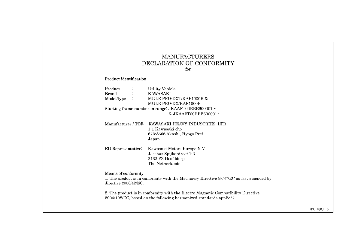
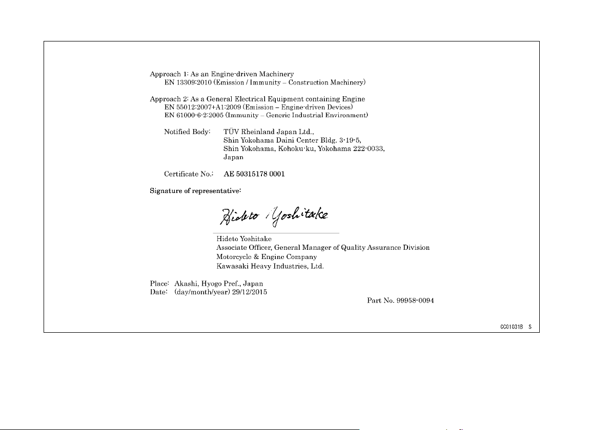
DECLARATION OF CONFORMITY
Page 19
18 DECLARATION OF CONFORMITY
Page 20
SERIAL NUMBER LOCATIONS 19
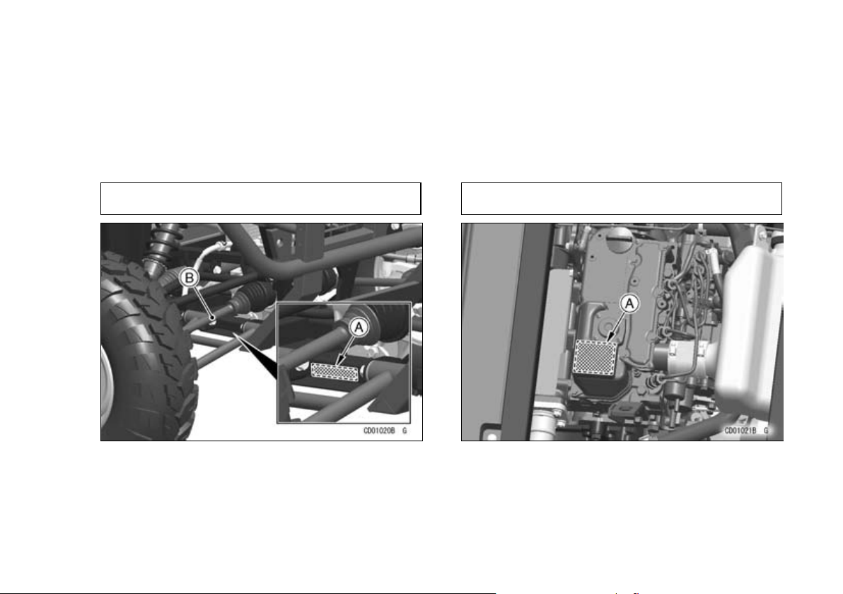
SERIAL NUMBER LOCATIONS
The engine and frame serial numbers are used to register the vehicle. They are the only means of identifying
your particular machine from others of the same model type. These serial numbers may be needed by your
dealer when ordering parts. In the event of theft, the investigating authorities will require both numbers as well
as the model type and any peculiar features of your machine that can help them identify it.
Frame No.
A. Frame Number
B. Right Front Axle
Engine No.
A. Engine Number
Page 21
20 LOCATION OF PARTS
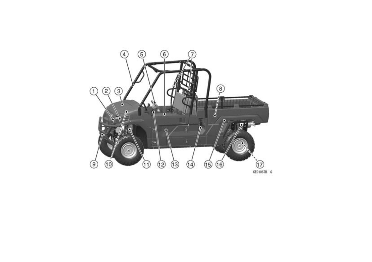
LOCATION OF PARTS
1. LED Sub Headlights
2. Headlights
3. Front Access Cover
4. ROPS (Roll Over Protective
Structure)
5. Steering Wheel
6. Seat
7. Seat Belts
8. Cargo Bed
9. Front Guard
10. Coolant Reserve Tank
11. Brake Fluid Reservoir
12. Steering Wheel Tilt Lock Lever
13. Door
14. Cargo Bed Latch
15. Cargo Bed Handgrip
16. Muffler (Spark Arrester)
17. Trailer Hitch Bracket
Page 22

LOCATION OF PARTS 21
1. Tailgate Latch Handle
2. Tailgate
3. Screen
4. Handgrip for Right Seat Passenger
5. Tail/Brake Light
6. Rear Shock Absorber
7. Air Cleaner
8. Battery
9. Fuel Tank Cap
10. Dashboard
11. Front Shock Absorber
12. Radiator
Page 23
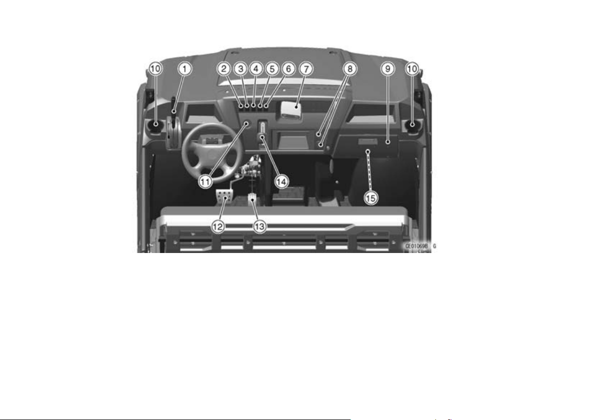
22 LOCATION OF PARTS
1. Parking Brake Lever
2. Horn Switch
3. Selectable DIFF-LOCK Shift
Switch
4. Selectable 2WD/4WD Shift
Switch
5. Headlight Switch
6. LED Sub Headlight Switch
7. Multifunction Meter
8. Power Outlet Sockets
9. Glove Compartment
10. Cupholders
11. Main Switch
12. Brake Pedal
13. Throttle Pedal
14. Gear Shift Lever
15. Tool Kit
Page 24
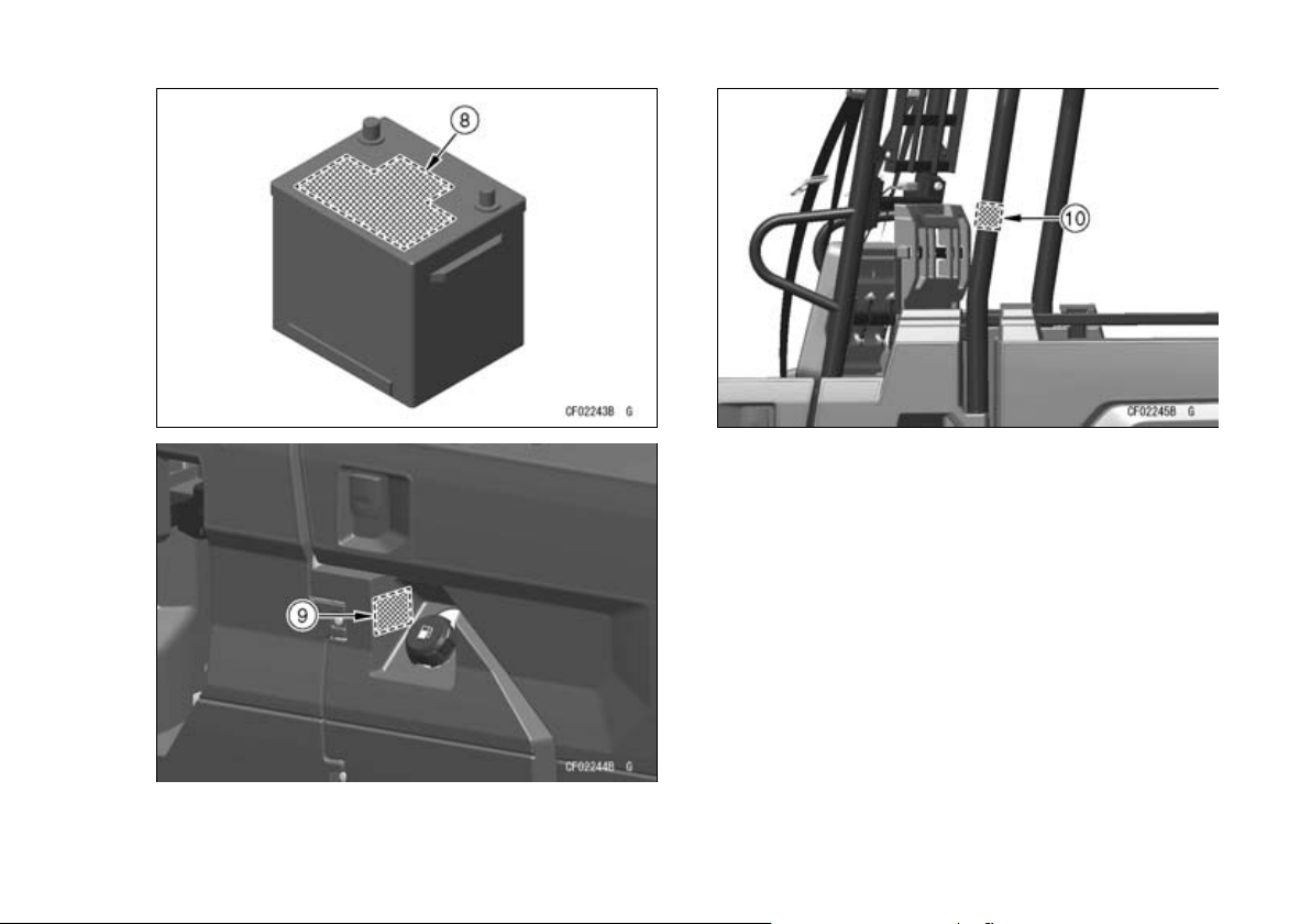
LOCATION OF LABELS
All warning labels which are on your vehicle are
repeated here. Read labels on your vehicle and
understand them thoroughly. They contain information which is important for your safety and the safety
of anyone else who may operate your vehicle.
Therefore, it is very important that all warning labels
be on your vehicle in the locations shown. If any label is missing, damaged, or worn, get a replacement
from your Kawasaki dealer and install it in the correct position.
NOTE
The sample warning labels in this section have
○
part numbers to help you and your dealer obtain
the correct replacem ent.
Refer to the actual vehicle label for model specific
○
data grayed out in the illustration.
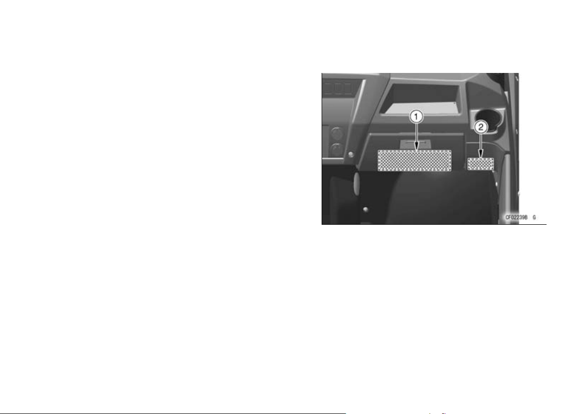
LOCATION OF LABELS 23
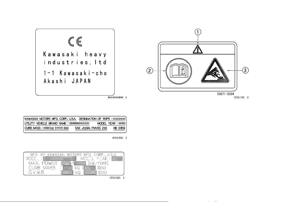
1. Warning (General)
2. CE Mark
Page 25
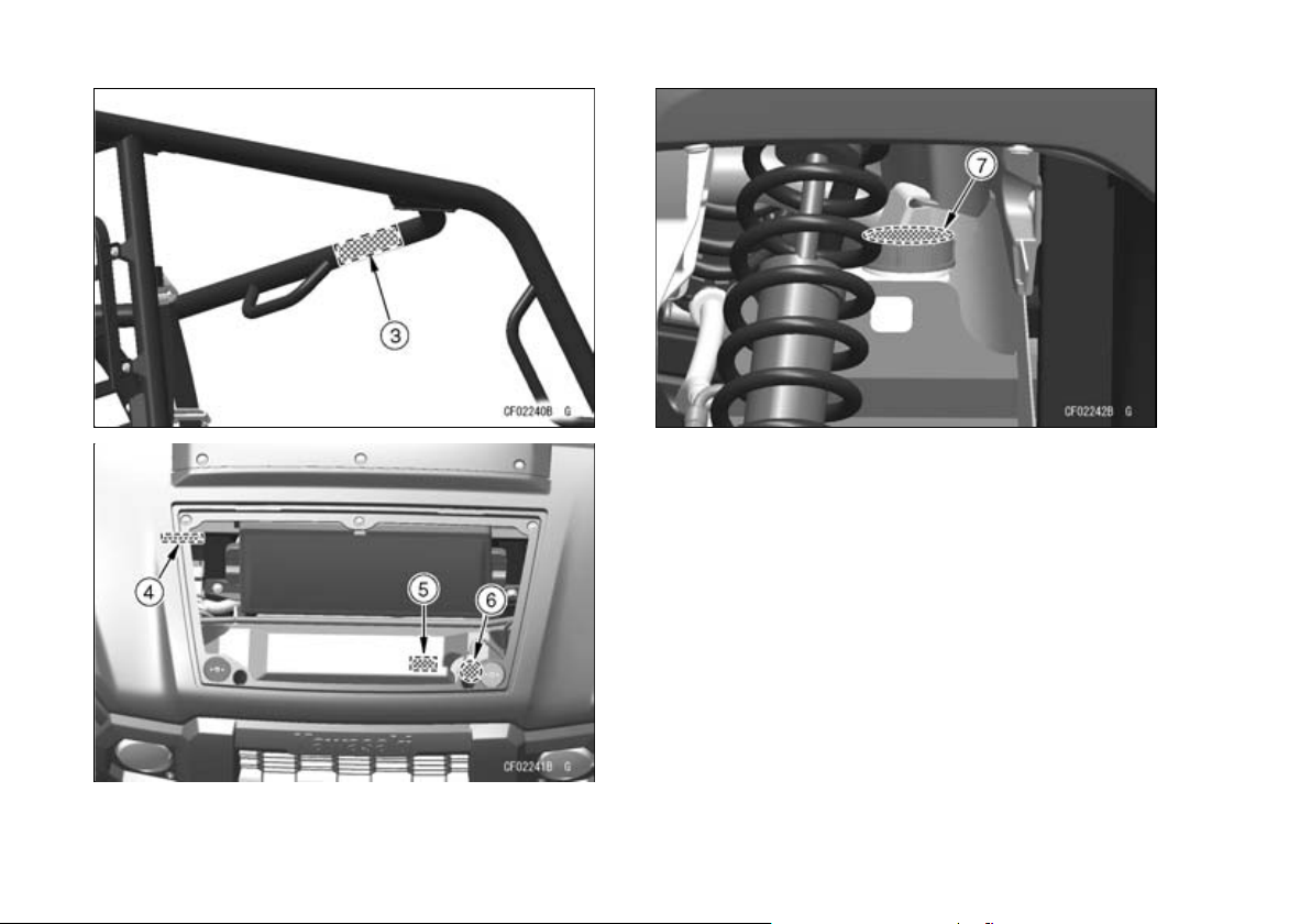
24 LOCATION OF LABELS
3. Specification (ROPS)
4. Specification (Model)
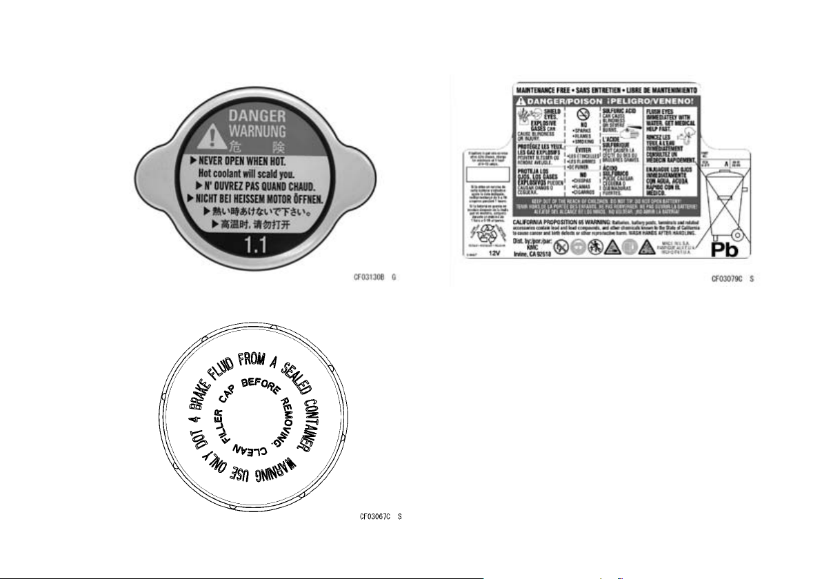
5. Danger (Radiator Cap)
6. Danger (Radiator Cap)
7. Warning (Brake Fluid)
Page 26
LOCATION OF LABELS 25
8. Danger/Poison (Battery)
9. Warning (Refueling)
10. Warning (Cargo Bed Lifting: both sides)
Page 27
26 LOCATION OF LABELS
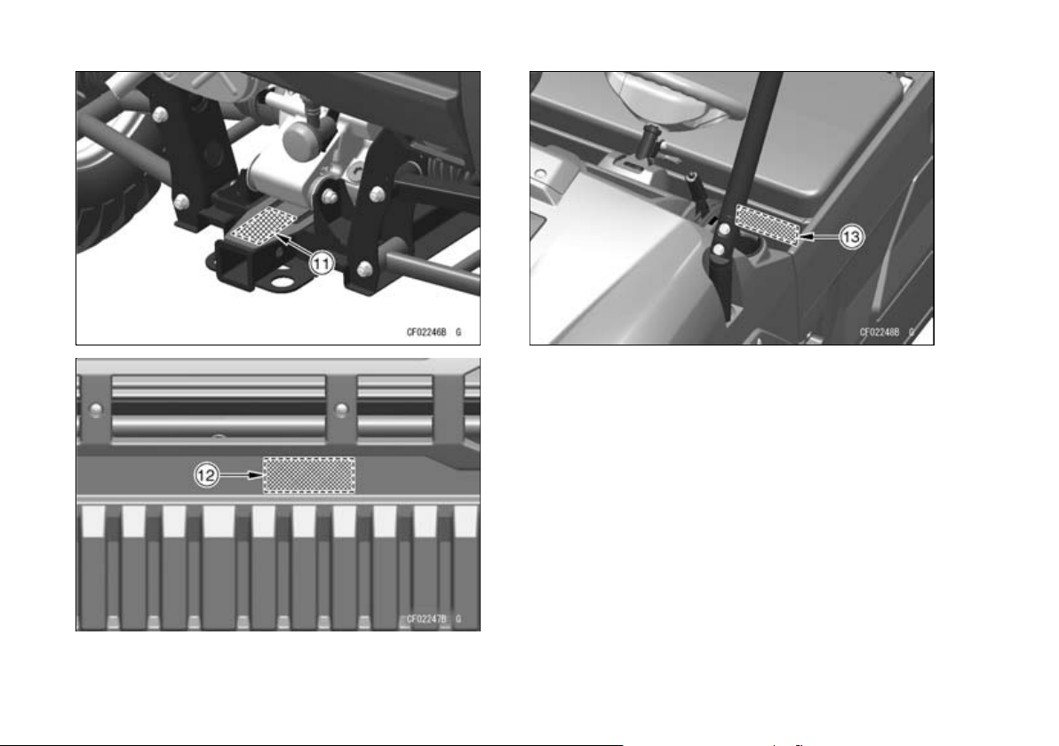
11. Warning (Trailer Towing)
12. Warning (Cargo Bed Loading)
13. Important Information (Tires/Max. Load)
Page 28
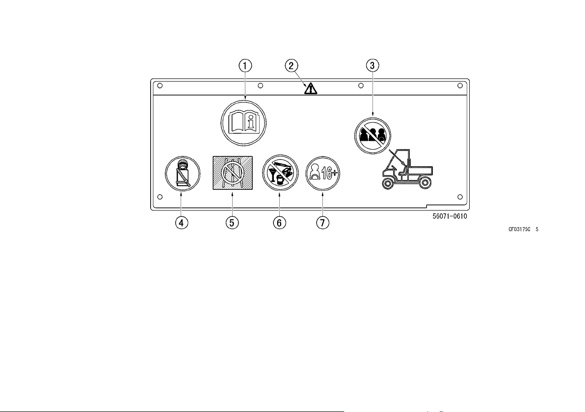
(1)
1. Read Owner’s Manual
2. Safety alert symbol
3. Maximum seating capacity: 2 persons, see
“BASIC SAFE DRIVING” section
4. Fasten seat belts. Wear an approved helmet
and protective gear, see “BASIC SAFE DRIVING” section
5. Never use on public roads, see “BASIC SAFE
DRIVING” section
6. Never use with drugs or alcohol, see “BASIC
SAFE DRIVING” section
7. Make sure operators are 16 years or older with
a valid driver’s license, see “BASIC SAFE
DRIVING” section
LOCATION OF LABELS 27
Page 29
28 LOCATION OF LABELS
(2)
(3)
(4)
(5)
1. Safety alert symbol
2. Read Owner’s Manual
3. Hot liquid. Never open when engine is hot, see
page 108
Page 30
LOCATION OF LABELS 29
(6)
(7)
(8)
Page 31

30 LOCATION OF LABELS
(9)
1. Read Owner’s Manual
2. Use diesel fuel only, see page 51
(10)
1. Safety alert symbol
2. Read Owner’s Manual
3. Hand crush, see page 48
Page 32

LOCATION OF LABELS 31
(11)
1. Safety alert symbol
2. Read Owner’s Manual
3. Maximum arm length
4. Vertical force limitation, see page 68
5. Horizontal force limitation, see page 68
Page 33

32 LOCATION OF LABELS
(12)
1. Safety alert symbol
2. Read Owner’s Manual
3. Maximum cargo bed load, see page 35
4. Never carry passengers in cargo bed, see page
51
Page 34

(13)
1. Read Owner’s Manual
2. Tire pressure, see page 128
3. Safety alert symbol
4. Load condition (including occupants and cargo), see page 128
5. Front tire size, see page 128
6. Rear tire size, see page 128
LOCATION OF LABELS 33
Page 35

34 LOADING INFORMATION
LOADING INFORMATION
WARNING
Incorrect loading, improper installation or use
of accessories, or modification of your vehicle may result in an unsafe operating condition. Before you operate it, make sure that the
vehicle is not overloaded and that you have
followed these instructions.
With the exception of genuine Kawasaki Parts
and Accessories, Kawasaki has no control over the
design or application of accessories. In some cases,
improper installation or use of accessories, or vehicle modifications, will void the utility vehicle warranty. In selecting and using accessories, and in
loading the vehicle, you are personally responsible
for your own safety and the safety of other person
involved.
NOTE
Kawasaki Parts and Accessories have been spe-
○
cially designed for us e on Kawasaki utility ve-
hicles. We strongly recommend that all parts and
accessories you add to your vehicle be genuine
Kawasaki components.
Because any vehicle is sensitive to increases in
weight and change s in weight distribution, you must
take ca re in carrying cargo. Always follow these precautions:
Carrying cargo, passenger and/or pulling a trailer
•
can make the vehicle difficult to steer and may affect vehicle handling in an unpredictable manner.
Use extreme caution when climbing and descending hills, and traversing slopes.
Braking distance is increased when carrying car-
•
go, passenger, and/or pulling a trailer. Reduce
speed and allow greater distance for braking.
All cargo should be carried as low as possible to
•
reduce the effect on the vehicle’s center of gravity.
Cargo weight should be equally distributed from
side to side. This helps maintain stability by centralizing weight. Avoid carrying cargo that extends
beyond the rear of the vehicle. Do not carry cargo
on top of the ROPS.
Cargo should be securely anchored. Make sure
•
the cargo will not move around while the vehicle is
moving. Recheck cargo security as often as possible (while the vehicle is stopped) and adjust as
necessary.
NOTICE
The front body work and fenders are not designed to carry cargo or to support weight.
Do not place cargo, lean or sit on them, or
they may break.
This vehicle is not designed to carry passengers
•
in the cargo bed. Installing additional passen ger
Page 36

seating or carrying passengers in the cargo bed
can cause changes in vehicle handling.
WARNING
Passengers transported in the cargo bed can
be tossed about or even thrown out causing
serious injury or death. Do not install seating
or trans port passengers in the cargo bed.
(Maximum Cargo Bed Load) Do not carry more
•
than maxi mum cargo bed load as specified below.
Maximum Cargo Bed Load: 453 kg (1 000 lb)
(Maximum Vehicle Load) Weight of operator, pas-
•
senger, cargo, accessories, and trailer tongue
must not exceed following limits.
Maximum Vehicle Load: 733 kg (1 616 lb)
Do not operate this vehicle faster than 16 km/h
•
(10 mph) when pulling a trailer. Refer to the
“Trailer Hitch Bracket” section in the “GENERAL
INFORMATION” chapter.
LOADING INFORMATION 35
Page 37

36 GENERAL INFORMATION
GENERAL INFORMATION
Multifunction Meter
1. Amber Glow Plug Indicator Light
2. Red EPS Warning Indicator Light
3. Speedometer
4. Fuel Level Gauge
5. Red Parking Brake Indicator Light
6. Red Reverse Indicator Light
7. Green Neutral Indicator Light
8. Right Button
9. Odometer/Trip Meters (Trip Meter A and B)/Hour
Meter
10.Clock
11. Left Button
12.“2WD” Indicator Symbol
13.Red Seat-Belt Use Reminder
14.Red Coolant Temperature Warning Indicator
Light
15.Red Oil Pressure Warning Indicator Light
16.“4WD” Indicator Symbol
Pushing the left button shifts the display in the
odometer/trip meters/hour meter through the 4
modes; odometer, trip meter A and B, and hour meter.
When the main switch is turned on, all the “LCD”
segments and “LED” lights are displayed for a second, then the clock and meters operate normally depending on the mode selected.
Page 38

GENERAL INFORMATION 37
Speedometer
The speed ometer shows the speed of the vehicle.
A. Speedometer
mph·km/h Display:
mph·km/h display can alternate between English
and metric modes (mph and km/h) in the digital meter. Make sure that mph or km/h is correctly displayed according to local regulations before driving.
Shift the mph·km/h display in the digital meter as follows.
The mph·km/h display shifts by pushing and hold-
•
ing the left button and pushing the right button
within two seconds.
A. mph·km/h Display
B. Left Button
C. Right Button
The mph·km/h display shifts as follows.
•
NOTE
Do not operate the vehicle with the digital meter
○
displaying in the wrong unit (mph or km/h).
Display the odometer in the digital meter.
•
NOTE
The data is maintained even if the battery is dis-
○
connected.
Page 39

38 GENERAL INFORMATION
Fuel Level Gauge
The fuel in the fuel tank is shown in segments. All
6 segments are displayed when the fuel tank is full.
As fuel is consumed the segments go out accordingly. When the bottom segment is reached, it will
begin blinking to warn of a low fuel level.
When it begins blinking, 6.6 liters (1.7 US gal) of
fuel remains. Fill the fuel tank as soon as possible
because there is no reserve tank in this vehicle (see
Fuel section).
A. Hour Display
B. Minute Display
Push the right button. The hour display only
•
blinks. Push the left button to advance the hours.
A. Blinking to warn of a low fuel level
Clock
To adjust hours and minutes:
Turn the main switch on.
•
The odometer is displayed.
•
Push the right button for more than two seconds.
•
Both the hour and minute displays start blinking.
A. Hour Display
Push the right button. The hour display stops
•
blinking and the minute display starts blinking.
Push the left button to advance the minutes.
Page 40

A. Minute Display
Push the right button. Both the hour and minute
•
displays start blinking again.
Push the left button. The displays stop blinking
•
and the clock starts working.
GENERAL INFORMATION 39
NOTE
When the figures come to 999999, they are
○
stopped and locked.
A. Odometer
NOTE
Pushing the left button momentarily advances the
○
hour or minute step by step. Pushing and holding
the button advances the hour or minute continuously.
The clock works normally from the back-up power
○
while the main switch is turned off.
When the battery is disconnected, the clock re-
○
sets to 1:00, and starts working again when the
battery is connected.
Odometer
The odometer shows the total distance in kilometers or miles that the vehicle has been driven.
The meter cannot be reset.
Trip Meters (Trip Meter A/B)
The trip meter shows the distance in kilometers or
miles traveled since it was last reset to zero.
To reset the trip meter:
Push the left button to display the trip meter A or
•
B.
Push the right button and hold it in.
•
After two seconds, the figure display turns to 0.0,
•
and then starts counting when the vehicle is oper-
ated. The meter counts until it is next reset.
NOTE
When the trip meter reaches 9999.9 when the ve-
○
hicle is running, it turns back to 0.0 and starts
counting again.
Page 41

40 GENERAL INFORMATION
A. Trip Meter A
Hour Meter
The hour meter shows the total hours that the vehicle has been operated. This meter cannot be reset.
NOTE
When the figures come to 99999.9, they are
○
stopped and locked.
A. Hour Meter
2WD/4WD Indicator Symbol
This vehicle can be driven in either “2WD” or
“4WD.”
When the selectable 2WD/4WD shift switch is in
“4WD,” the “4WD” indicator symbol will appear.
After shifting there is a momentary delay before
the indicator symbols change.
Page 42

GENERAL INFORMATION 41
A. “2WD” Indicator Symbol
B. “4WD” Indicator Symbol
A. Amber Glow Plug Indicator Light
B. Red EPS Warning Indicator Light
C. Red Parking Brake Indicator Light
D. Red Reverse Indicator Light
E. Green Neutral Indicator Light
F. Red Seat-Belt Use Reminder
G. Red Coolant Temperature Warning Indicator
Light
H. Red Oil Pressure Warning Indicator Light
Amber Glow Plug Indicator Light
The glow plug indicator light goes on for 4 seconds when the main switch key is turned to the “ON”
position. The indicator light also goes on whenever
the key is in the “START” position. The indicator light
goes off after the plug is fully heated. If it does not
go on or go off, have the glow plug and related system checked by an authorized Kawasaki dealer.
Page 43

42 GENERAL INFORMATION
Refer to the “Starting the Engine” section in the
“HOW TO OPERATE” chapter for detailed informa-
tion.
Red EPS Warning Indicator Light
The EPS warning indicator light will momentarily
illuminate when the engine starts, then go off in a
second if the system is in order. If this warning indicator light illuminates any other time, it indicates the
ECU or actuator has malfunctioned, or the wiring
harness has become disconnected. Stop driving immediately and contact an authorized Kawasaki
dealer to have the system checked.
NOTE
If this warning indicator light does not go on when
○
the main switch is turned on, there may be a prob-
lem with the light itself. Contact an authorized Ka-
wasaki dealer for inspection.
Red Parking Brake Indicator Light
When the parking brake is applied with the main
switch in the “ON” position, the parking brake indicator light illuminates.
Red Reverse Indicator Light
When the transmission is in reverse gear, the reverse indicator light illuminates.
Green Neutral Indicator Light
When the transmission is in neutral, the neutral indicator light illuminates.
Red Seat-Belt Use Reminder
When the main switch is turned on, the seat-belt
use reminder will illuminate and stay on for approximately 8 seconds, even if the operator's belt is
buckled. The light is a reminder to the operator to
make sure that passengers have buckled their seat
belts.
Red Coolant Temperature Warning Indicator
Light
The coolant temperature warning indicator light illuminates whenever the coolant temperature rises
too high while the vehicle is in operation. If it stays
on, stop the engine and check the coolant level in
the coolant reserve tank after the engine cools
down.
Be sure to check that the radiator fan is free from
mud and other obstacles. Refer to the “Breaker”
section in the “MAINTENANCE AND ADJUSTMENT” chapter.
NOTICE
Do not continue running the engine with the
temperature warning indicator light continuously illuminated. Prolonged engine operation can result in engine damage from
overheating.
NOTE
When you touch the fan, be sure to disconnect
○
the negative ( –) battery cable, since the fan can
Page 44

GENERAL INFORMATION 43
operate automatically even with the main switch
off.
Red Oil Pressure Warning Indicator Light
The oil pressure warning indicator light blinks to
warn the oper ator whenever the oil pressure is dangerously low or the main switch is in the “ON” position with the engine not running, and goes off when
the proper engine oil pressure is reached. Refer to
the “MAINTENANCE AND ADJUSTMENT” chapter
for more detailed engine oil information.
Lighting/Electrical Accessory Socket
The lighting/electrical accessory 12 volt sockets
are located on the dashboard.
An auxiliary light or an accessory may be con-
nected to these connectors.
A. Power Outlet Sockets
NOTICE
Do not connect a light or load of more than
120 watts on one or both sockets, or the battery may rapidly discharge.
Page 45

44 GENERAL INFORMATION
Light Switches
The light switches are 3-position type with an indi-
cator.
The headlights can be turned on by pushing the
headlight switch to the “
when the main switch is in the “ON” position.
: Low Beam
: High Beam
When the headlights are on high beam, the high
beam indicator light in the switch goes on as a reminder. The headlights go off when the headlight
switch is pushed in “OFF” position.
” or “ ” position
A. High Beam Position
B. Low Beam Position
C. OFF Position
D. High Beam Indicator Lights
E. Headlight Switch
F. LED Sub Headlight Switch
This vehicle is equipped with LED sub headlights.
The operation of the LED sub headlight switch is
similar with the headlight switch.
Page 46

A. Headlights
B. LED Sub Headlights
GENERAL INFORMATION 45
Steering Wheel
This vehicle is equipped with an electric power
steering system. The system does not require regular maintenance by users. Do not tamper with the
electronic control unit (ECU) or loosen the fittings of
steering actuator, or the neutral position setting of
the steering will be adversely affected and will
cause serious driving problems. If such components
need service, contact an authorized Kawasaki dealer.
If the steering becomes more difficult than usual
or you feel a steering problem, refer to the “Steering
Wheel” section in the “MAINTENANCE AND ADJUSTMENT” chapter.
A. Steering Wheel
Page 47

46 GENERAL INFORMATION
NOTE
The power steering system functions only when
○
engine is running.
If you install wireless equipment on board, contact
○
an authorized Kawasaki dealer. Installing such
equipment improperly may affect the ECU.
Steering Position Adjustment
The steering wheel position can be adjusted to
suit the operator.
Make any steering wheel adjustment before start-
ing the vehicle.
WARNING
Adjusting the steering wheel position while
driving could cause loss of control and an accident resulting in serious injury or death. To
prevent loss of control, do not adjust the
steering wheel position unless the vehicle is
stopped.
Move the steering wheel up or down while pulling
•
up the tilt lock lever under the steering wheel.
Release the tilt lock lever to lock the steering
•
wheel in position.
A. Tilt Lock Lever
B. Pull up.
C. Steering Wheel
D. Adjusting Direction
NOTE
Make sure you have securely locked the steering
○
wheel in place by moving it up and down.
Page 48

GENERAL INFORMATION 47
Brake Pedal
The brake pedal is the left pedal on the floorboard.
Depress the pedal to slow or stop the vehicle.
A. Brake Pedal
B. Floorboard
Cargo Bed
Tailgate
The tailgate of the cargo bed can be lowered. Before lowering the tailgate, park on a firm level surface and set the parking brake.
To open the tailgate, release the latches and lower
the tailgate. Cables hold the tailgate level with the
cargo bed.
A. Tailgate
B. Latch Handle (Both Sides)
To close the tailgate, lift to the upright position and
secure firmly with the latches.
Push the tailgate latch handles forward to make
sure the latches stay securely closed. Do not drive
the vehicle with the tailgate lowered.
Page 49

48 GENERAL INFORMATION
A. Tailgate
B. Cable
Lifting and Lowering the Cargo Bed
WARNING
Reduced clearance between the cargo bed
and the cargo screen ma y trap and seriously
injure an arm while lifting or lowering the cargo bed. To avoid possible injury, do not place
hands on any part of the cargo screen when
lifting or lowering the cargo bed.
The cargo bed can be tilted by releasing the
latches on each side, and then lifting the bed with
the handgr ips.
A. Cargo Bed Latch (Both Sides)
B. Handgrip (Both Sides)
Lifting the Cargo Bed
Before tilting the cargo bed, park on a firm level
•
surface and set the parking brake.
Empty the cargo bed prior to raising the cargo
•
bed.
Lift the bed with the handgrips. The supporting
•
damper under the cargo bed helps lifting the bed.
Pull the supporting rod out of its mounting clip on
•
the front of the cargo bed.
Page 50

GENERAL INFORMATION 49
A. Supporting Rod
B. Pull here to free rod from clip.
C. Cargo Bed
D. Clip
E. Forward
With the cargo bed at the highest position, hook
•
the ring of the supporting rod on the stopper pin of
the bottom horizont al bar of the screen.
A. Supporting Damper
B. Cargo Bed (Tilted Position)
C. Supporting Rod
D. Ring of the supporting rod
E. Screen
F. Stopper Pin
WARNING
Using only the bed supporting damper for
cargo bed support may allow the cargo bed to
suddenly lower. To prevent injury caused by
sudden lowering of the cargo bed, support
the cargo bed with the support rod whenever
lifting the cargo bed.
Page 51

50 GENERAL INFORMATION
Lowering the Cargo Bed
Before lowering the bed, check to be sure the
•
area under it is clear.
Return the supporting rod to its original position
•
and secure it with the clip.
To lower the cargo bed pus h down the side rail of
•
the cargo bed. And then hold the handgrip with
another hand and carefully lower the bed in place.
Latch both latches and check that the bed is prop-
•
erly locked into place. Do not leave the cargo bed
unlatched.
A. Cargo Bed Latch (Locked Position)
B. Side Rail
Do not drive the vehicle with the front end of the
•
cargo bed raised or unlatched.
WARNING
The front of the cargo bed becomes heavier
as it lowers into position and can suddenly
lower, trapping arms between the bed and
frame causing serious injury. To prevent the
bed from suddenly lowering, use the handgrips to properly support the bed when lowering or lifting the bed.
Loading Cargo Bed
NOTICE
Do not carry more than 453 kg (1 000 lb) in the
cargo bed.
Page 52

GENERAL INFORMATION 51
WARNING
Overloading, failure to properly secure car-
•
go, or improper use of the cargo bed can
cause changes in handling which can lead
to an accident. Follow guidelines provided
in the “LOADING INFORMATION” chapter.
Passengers transported in the cargo bed
•
can be tossed about or even thrown out
causing serious injury or death. Do not install seating or transport passengers in the
cargo bed.
Driving with the cargo bed tilted may be
•
hazardous. Failure to lower and lock the
bed into place may cause serious injury or
death. Al ways lower and latch the bed after
tilting.
Fuel
Diesel Fuel Requirements
Kawasaki recommends diesel fuels that meet the
following requirements for use in this vehicle. Use
clean, fresh diesel fuel to maintain performance and
life from the engine.
Fuel Specification and Cetane Number
(1) The diesel fuel must meet the European EN590
specification.
(2) Use diesel fuel with a cetane number equal to
or higher than that shown below. If available in
your area, a high cetane “premium” diesel fuel
may offer improved cold-starting and warm-up
performance.
Fuel type: Diesel fuel for vehicle
Minimum cetane number: 45
Lower Sulfur
A sulfur content less than 0.05% by volume is recommended. To avoid engine corrosion, and engine
oil contamination, do not use fuel with more than
0.5% sulfur content.
When using CJ-4 oil (low ash oil) in your engine,
use fuel with less than 0.05% sulfur content to avoid
engine oil deterioration.
Cold Weather Information
In cold weather, diesel fuel may thicken enough to
clog the fuel filter. This is usually caused by naturally-occurring paraffin in diesel fuel turning to wax
Page 53

52 GENERAL INFORMATION
as it gets colder. If the engine starts but stalls after a
short time and will not restart, the fuel filter may be
clogged. For best results in cold weather use winter
diesel fuel.
WARNING
Starting fluids such as ether are explosive
and may cause severe injury. Do not use
starting fluids containing ether in the air intake system.
NOTICE
Do not add gasoline, gasohol, alcohol or
aftermarket cetane improver additives to diesel fuel. Damage to the fuel injection system
may result.
NOTICE
Wax flakes in the fuel tank could damage the
fuel level sensor. At temperatures below –10°
C (14 °F), use winter diesel fuel to prevent the
diesel fuel from turning to wax.
Using Biodiesel Fuel
Biodiesel fuels blended with diesel fuel may be
used in this vehicle only if the blended fuel meets
the following conditions:
(1) Biodiesel fuel concentration must not exceed
7% by volume (B7).
(2) The petroleum diesel fuel base must meet the
European EN590 specification. The pure biodiesel base must meet the European Standard
EN14214. Raw pressed vegetable oils are NOT
acceptable for use in any concentration.
Precautions when Using Biodiesel Fuels
(1) Cranking time when engine starting in cold
weather will be prolonged.
(2) Biodiesel blended fuel attracts mois ture and
may contain higher water content than conventional diesel fuels. Keep storage and vehicle
tanks as full as possible and ensure all caps
and covers are installed properly to prevent
water from entering and collecting in the fuel
system.
(3) Clean up any spilled fuel immediately to prevent
damage to painted surfaces.
(4) To avoid damage caused by fuel degrada tion,
biodiesel blended fuel should not be used if it
has been stored for more than 3 months. If an
engine is going to be placed in storage, the biodiesel blended fuel should be flushed out by operating the engine for at least 30 minutes on
conventional diesel fuel after replacing biodiesel
fuel in the vehicle fuel tank with petroleumbased diesel fuel.
Filling the Fuel tank
The fuel tank is mounted under the right side of
the seat. Use only fresh diesel fuel with the recommended cetane number from an uncontaminated
Page 54

source to ensure proper running of your vehicle.
Avoid filling the tank in the rain or where heavy dust
is blowing so that the fuel does not get contaminated.
GENERAL INFORMATION 53
A. Filler Neck
B. Fuel Top Level (Bottom of Filler Neck)
C. Fuel Tank
A. Fuel Tank Cap
Never fill the tank completely to the top. After refueling, make sure the fuel tank cap is closed securely.
NOTICE
Always clean dirt/mud/debris/water from the
fuel tank cap and surrounding area prior to
filling the tank to prevent dirt/mud/debris/water from entering the fuel tank. Accumulation of moisture or sediment in the fuel
system can restrict the flow of fuel and cause
fuel system and/or engine damage.
Page 55

54 GENERAL INFORMATION
WARNING
Diesel fuel is extremely flammable and can
ignite under certain conditions. To avoid the
potential for burns or other injuries when refueling, turn the main switch key off. Do not
smoke. Make sure the area is well ventilated
and free from any source of flame or sparks;
this includes any appliance with a pilot light.
Never fill the tank completely to the top. After
refueling, make sur e the fuel tank cap is
closed securely. If diesel fuel is spilled on the
fuel tank, wipe it off immediately.
Glove Compartment/Tool Kit
A glove compartment is provided at the right side
of the dashboard. Store only light items to avoid
damage to the inside of the compartment. Do not
store items which must not get wet or dirty.
The tool kit is located at the inside of the glove
compartment.
A. Glove Compartment
B. Tool Kit
Page 56

GENERAL INFORMATION 55
Cupholders
Cupholders are provided at the left and right sides
of the dashboard.
A. Cupholder (Both Sides)
Front Access Cover
The front access cover can be removed for main-
tenance such as a coolant level inspection.
NOTICE
Do not store items under the front access
cover. This area is not designed for storage.
Cover Opening
Turn the knobs counterclockwise 90° to release
•
the locks.
Pull the front of the front access cover up and
•
open the cover.
A. Front Access Cover
B. Knobs
Page 57

56 GENERAL INFORMATION
Pull the front access cover forward to disengage
•
the tabs from the slits of the front hood.
A. Front Access Cover
B. Tabs
C. Slits
Cover Closing
Insert the tabs on the front access cover to the
•
slits of the front hood.
Lower the front access cover and turn the knobs
•
clockwise until they stop to lock the front access
cover.
A. Front Access Cover
B. Knob (Both Sides)
Pull up the front ends of the front access cover to
•
make su re the cover is locked securely.
WARNING
An open front access cover can distract or
impair visibility of the operator, causing loss
of vehicle control and potential serious injury
or death.
Lock the front access cover securely before
operating the vehicle.
Page 58

GENERAL INFORMATION 57
Horn Switch
Push the horn switch to sound the horn.
A. Horn Switch
Main Switch
This is a three-position, key-operated switch. The
key can be removed from the switch only when it is
in the “OFF” position.
A. Main Switch
B. “OFF” Position
C. “ON” Position
D. “START” Position
Page 59

58 GENERAL INFORMATION
OFF Engine off. All electrical circuits off.
ON
START
All electrical equipment can be used.
Hour meter works.
Electric starter is engaged by holding
main swi tch key in this position, only
when gear shift lever is in “N” (neutral)
position or applying brake pedal. Upon
release, key will return to “ON” position.
NOTICE
Do not operate the starter continuously for
more than 5 seconds, or the starter will overheat and the battery power will drop temporarily. Wait 15 seconds between each operation
of the starter to let it cool and for the battery
to recover power.
Do not turn the main switch key to the
“START” position with the engine running, or
damage to the starter can result.
NOTE
The vehicle is equipped with a starter lockout sys-
○
tem. This system prevents the electric starter from
operating when the gear shift lever is in the “H”
(High), “L” (Low) or “R” (Reverse) position, unless
the brake is applied.
Blank keys are available at your Kawasaki dealer.
Ask your dealer to make any additional spare keys
you need, using your original key as a master.
Gear Shift Lever
The gear shift lever is located on the dashboard,
to the right side of the steering wheel. The gear shift
lever has four positions: “L” (Low), “H” (High), “N”
(Neutral), and “R” (Reverse).
Make certain that the vehicle is completely
stopped and the engine is idling before shifting from
“H” (High) or “L” (Low) to “R” (Reverse) or vice versa. Move the gear shift lever up or down as indicated on the embossed mark next to the gear shift
lever.
Refer to the “Shifting Gears” section in the “HOW
TO OPERATE” chapter.
Page 60

A. Gear Shift Lever
B. “L” (Low) Position
C. “H” (High) Position
D. “N” (Neutral) Position
E. “R” (Reverse) Position
NOTICE
Do not shift from “H” (High) or “L” (Low) to
“R” (Reverse) and vice versa when the ve-
hicle is moving or with the engine running
above idling speed, or the transmission could
be damag ed.
GENERAL INFORMATION 59
range for ordinary off-highway use. Stop the vehicle
before moving the gear shift lever.
NOTICE
Use of the high range for heavy loads, climbing hills, and pulling a trailer can lead to premature wear of the torque converter belt and
pulleys. Use low range for these conditions.
Refer to the “Shifting Gears” section in the “HOW
TO OPERATE” chapter.
This vehicle is equipped with a sub-transmission
to allow maximum transmission efficiency. Use the
low gearing for maximum torque at low speeds, for
climbing hills, pulling a trailer, or keeping constant
low sp eeds. The high gearing raises the speed
Page 61

60 GENERAL INFORMATION
Selectable 2WD/4WD Shift Switch
You can select “2WD” or “4WD” to suit various
driving conditions. The selectable 2WD/4WD shift
switch is located on the dashboard.
A. Selectable 2WD/4WD Shift Switch
B. “2WD” Position
C. “4WD” Position
The current operating condition is indicated with
the 2WD/4WD indicator symbols in the multifunction
meter.
A. “2WD” Indicator Symbol
B. “4WD” Indicator Symbol
Refer to the “Multifunction Meter” section in this
chapter, together with the “2WD/4WD Shifting” section in the “HOW TO OPERATE” chapter.
WARNING
The handling characteristics of this vehicle
differs between “2WD” and “4WD” according
to terrain. Changing the operating mode while
moving can cause sudden changes in handling performance which can cause the operator to lose control and have an accident.
Always stop the vehicle before changing from
“2WD” to “4WD” and vice versa.
Page 62

GENERAL INFORMATION 61
NOTICE
Shifting from “2WD” to “4WD” (or “4WD ” to
“2WD”) when the vehicle is in motion could
cause drive train damage.
Selectable DIFF-LOCK Shift Switch
You can select differential “LOCK” (locked-rear
axle) or “UNLOCK” (unlocked-rear axle) modes to
suit various driving conditions. The selectable DIFFLOCK shift switch is located on the dashboard.
A. Selectable DIFF-LOCK Shift Switch
B. “LOCK” Position (Locked-Rear Axle Mode)
C. “UNLOCK” Position (Unlocked-Rear Axle Mode)
D. DIFF-LOCK Indicator Light
The “LOCK” (locked-rear axle) condition is indicated by a light in the switch as a reminder. Refer to
the “Shifting the Differential” section in the “HOW
TO OPERATE” chapter.
Page 63

62 GENERAL INFORMATION
Belt Drive Transmission
This vehicle is equipped with a belt-driven Continuously Variable Transmission (CVT). This automatic
drive system , although simple to operate, does require periodic inspection. Refer to the “MAINTENANCE AND ADJUSTMENT” chapter.
Parking Brake Lever
The parking brake lever is located at the left side
of the steering wheel. Pull the lever rearward to apply the parking brake.
To release, push in and hold the knob on the end
of the lever and push the lever all the way forward.
Spring pressure helps return the lever to the released pos ition.
Be sure to release the parking brake before driving off. Failure to do so may result in poor performance and premature wearing of the rear brakes and
belt converter system.
The alarm buzzer will sound if the vehicle is running with the parking brake applied. Stop the vehicle
and release the parking brake.
A. Parking Brake Lever
B. Knob
Page 64

GENERAL INFORMATION 63
WARNING
If the vehicle should move after it is parked, it
might be damag ed or cause injury. Be sure to
apply the parking brake before leaving the vehicle.
Doors
Pull the door handle outward to open the door.
Push or pull the door inward until the latch clicks
to close the door. After closing the door, be sure to
check that the latch is securely locked. If a door is
damaged or does not close securely, contact an authorized Kawasaki dealer for repair or replacement.
A. Door Handle
B. Door
C. Latch
NOTE
Make su re that the all doors are properly closed
○
before starting the vehicle.
Page 65

64 GENERAL INFORMATION
NOTICE
The doors are not designed to bear weight.
Never lean on or place excessive weight on
the doors or they will be damaged.
Seat
The seat can be removed for vehicle maintenance
and adjustment.
Seat Removal
Pull up the right and left ends of the seat to clear
•
the projections.
Remove the seat.
•
A. Seat
B. Projections
C. Pull up.
Seat Installation
Make su re that grommets are in position.
•
Insert the projections of the seat into the grom-
•
mets.
Page 66

A. Seat
B. Projection (Both Sides)
C. Grommet (Both Sides)
GENERAL INFORMATION 65
Seat Belts
The vehicle is equipped with retractable threepoint seat belts for all occupants - operator and passenger. Always wear the seat belts when operating
and riding in the vehicle.
A. Seat Belt
B. Latch Plate
C. Buckle
WARNING
Not wearing a seat belt, or wearing one improperly can result in serious injury or death
in the event of an accident. Make certain the
operator and passenger always wear their
seat belts properly.
Page 67

66 GENERAL INFORMATION
WARNING
Operator and passenger must be able to
place both feet flat on the floorboards while
seated upright with their backs against the
seatbacks.
To wear the seat belt properly, follow this proce-
dure:
1. Place the belt across your lap and chest taking
care that the belt is not twisted.
2. Push the latch plate into the buckle until it clicks.
Pull up on the latch plate to make sure it is secure.
3. Put the lap portion of the belt low on your hips.
Push down on the buckle end of the belt as you
pull up on the shoulder part so the belt is snug
across yo ur hips.
4. Place the shoulder belt over your shoulder and
across your chest. The shoulder belt should fit
against your chest. If it is loose, pull the belt out
all the way and then let it retract.
A. Lap Portion of Belt
B. Shoulder Belt
5. To unfasten the belt, press the red button in the
buckle.
A. Seat Belt
B. Latch Plate
C. Buckle
D. Red Button
WARNING
Too much seat belt slack could reduce its protection effectiveness in an accident. Always
verify that the belt is at a SNUG FIT.
Page 68

GENERAL INFORMATION 67
The seat belt is equipped with a dual mode latch
plate. Under normal driving conditions the belt will
self adjust to the seat occupant so that it is snug
around both the occupant's waist and shoulder.
Under rough driving situations the dual mode latch
plate will lock the seat belt in place.
To release the lock:
Move the slider in the direction of the arrow mark.
•
A. Slider
B. Arrow Marks
Throttle Pedal
The throttle pedal is the right pedal on the floorboard. Push the pedal down to increase engine
speed. Spring pressure returns the pedal to the rest
position when released. Always check that the throttle pedal returns normally before starting the engine.
In addition, there must be adequate throttle pedal
play and correct throttle stop position adjustment.
Refer to the “MAINTENANCE AND ADJUSTMENT”
chapter for the throttle pedal adjustment procedure.
A. Throttle Pedal
B. Floorboard
Page 69

68 GENERAL INFORMATION
Trailer Hitch Bracket
This vehicle is equipped with a bracket for a trailer
hitch. Trailer towing equipment is not supplied with
this vehicle.
To avoid injury and property damage, observe the
following precautions:
WARNING
Improper towing of a loaded trailer could
cause an accident resulting in serious injury
or death.
Never carry a passenger in a trailer.
•
Never load more than 68.1 kg (150 lb)
•
tongue weight on the towing bracket.
Do not operate the vehicle faster than 16
•
km/h (10 mph) when towing. Remember that
towing a trailer increases braking distance.
Do not tow more than 907 kg (2 000 lb)
•
trailer weight (trailer plus cargo weight).
Attach a trailer to the trailer hitch bracket
•
only. Do not attach a trailer to any other location or you may lose control of the vehicle and have an accident.
A. Trailer Hitch Bracket
Page 70

BREAK-IN
The first 20 hours or 200 km (120 mile) of vehicle
operation is designated as the break-in period. Do
not exceed 1/2 throttle during the break-in period. If
the vehicle is not used carefully during this period,
you may end up with a “broken down” instead of
“broken in” vehicle.
Break-in period Maximum throttle position
First 20 hours or
200 km (120 mile)
Do not start moving or race the engine immedi-
○
ately after starting it, even if the engine is already
warm.
Do not race the engine while the transmission is
○
in neutral.
It is important to perform the initial service after
○
the first 20 hours or 200 km (120 mile) of opera-
tion as described in this manual and the service
manual for this vehicle. See the “Periodic Mainte-
nance Chart” in the “MAINTENANCE AND AD-
JUSTMENT” chapter.
1/2 throttle
NOTE
BREAK-IN 69
Page 71

70 HOW TO OPERATE
HOW TO OPERATE
Daily Checks
Check the following items each day before operation. The time required is minimal, and habitual performance
of these checks will help ensure safe, reliable operation.
If any irregularities are found during these checks, refer to the “MAINTENANCE AND ADJUSTMENT” chapter, see your dealer, or refer to the Service Manual for the action required to return the vehicle to a safe operating condition.
WARNING
Failure to perform these checks before operation may result in serious damage or an accident. Always per form daily checks before operation.
DANGER
Exhaust gas contains carbon monoxide, a colorless, odorless poisonous gas. Inhaling carbon monoxide can cause serious brain injury or death. DO NOT run the engine in enclosed areas. Operate only in a well-ventilated area.
Fuel ................................................... Enough fuel in tank, no leaks.
Fuel Filter .......................................... Check filter element for contamination.
Water Separator ............................... Check for water accumulation and filter element contamination.
Engine Oil ......................................... Oil level between Full and Low holes on the dipstick (when engine is
cold), no leaks.
Tires .................................................. Air pressure (when cold):
Page 72

HOW TO OPERATE 71
Tire Load Cold Tire Pressure
Front Up to 733 kg (1 616 lb) 78.4 kPa (0.80 kgf/cm², 11.4 psi)
Rear
Up to 590 kg (1 300 lb) 110 kPa (1.12 kgf/cm², 16.0 psi)
590 ~ 733 kg (1 300 ~ 1 616 lb)
130 kPa (1.33 kgf/cm², 18.9 psi)
Check for cuts, cracks, damage, or excessive wear. Check for any im-
bedded stones or other foreign particles in tread.
Front Final Gear Case Oil ................. Oil level come to the bottom of the filler opening, no leaks.
Transmission Case Oil ...................... Oil level between high and low levels on the rib in the oil filler opening,
no leaks.
Coolant ............................................. Coolant level between level lines (when engine is cold), no leaks.
Air Cleaner Element .......................... Check for dirt; clean or replace as required.
Screen at Belt Drive Transmission
(CVT) Air Duct .............................. Check and clean the screen for obstruction by insects, mud or foreign
object.
Throttle .............................................. Throttle pedal free play 2 ~ 10 mm (0.08 ~ 0.39 in.). Throttle pedal op-
erates smoothly and returns to rest position when released.
Steering ............................................ Steering wheel free play 0 ~ 20 mm (0 ~ 0.79 in.). Action smooth with-
out exce ssive play, rough spots, or strange noises.
Brakes ............................................... Check for braking effectiveness (while test running). Brake pedal free
play 2 ~ 10 mm (0.08 ~ 0.39 in.). Brake fluid level between level lines,
no leaks. Parking brake: Stops vehicle completely. Visually check the
return springs for damage.
Parking Brake Indicator .................... Make sure the parking brake indicator light illuminates when the park-
ing brake is applied with the main switch in the “ON” position.
Electrical Equipment ......................... All lights work. Check for dirt on or damage to lights.
ROPS ............................ .................... Make sure there is no damage to the structure or loose bolts.
Seat Belts ......................................... Make sure that all seat belts are in good condition and operate prop-
erly. The belt should pull smoothly and retract when released. The latch
plate should click securely with the buckle and release when the re-
lease button is pushed firmly.
Page 73

72 HOW TO OPERATE
Doors ................................................ Make sure there is no damage to the structure or loose bolts and all
doors are latched securely they are closed.
Page 74

HOW TO OPERATE 73
Starting the Engine
DANGER
Exhaust gas contains carbon monoxide, a
colorless, odorless poisonous gas. Inhaling
carbon monoxide can cause serious brain injury or death. DO NOT run the engine in enclosed areas. Operate only in a wellventilated area.
Close all doors.
•
Wear the seat belts (for an operator and passen-
•
ger).
Make su re the parking brake is applied.
•
Put the gear shift lever in the “N” (neutral) posi-
•
tion.
Put the main switch key in the main switch.
•
Turn the main switch key to the “ON” position. The
•
glow plug system is designed so that the glow
plug indicator light goes on at that time, and turn
off after 4 seconds.
After the glow plug indicator light turns off, turn the
•
main switch key to the “START” position to acti-
vate the electric starter. Repeat until the engine
starts.
NOTICE
Do not operate the electric starter continuously for more than 5 seconds, or the starter
may overheat and the battery power will drop
temporarily. Wait 15 seconds between each
operation of the starter to let it cool and for
battery power to recover.
NOTE
The vehicle is equipped with a starter lockout sys-
○
tem. This system prevents the electric starter from
operating when the gear shift lever is in the “H”
(High) , “L” (Low) or “R” (Reverse) position, unless
the brake is applied.
High-Altitude Injection Control Device
This vehicle has a high-altitude injection control
device installed. It suppresses black smoke when
operating at high altitudes and at the same time
aims to control particulate matter.
The control device measures the atmospheric
pressure just after the engine has started. If at this
time the control device determines that the altitude
is 800 m (2 600 ft) or more, it reduces the fuel injection amount and thus controls the occurrence of
black smoke.
Because of this reduction in the injection amount,
the engine output decreases.
Page 75

74 HOW TO OPERATE
NOTE
The high-altitude injection control device does not
○
actuate during engine operation. Therefore, when
the machine is moved to a high altitude or to a low
altitude during operation, turn the main switch key
to the “OFF” position. This resets the control device. After re-starting the engine, the necessity for
injection control is again determined.
Cold Weather Starting
Idling speed may not be stable and/or the engine
could stall when it is started in cold weather. However this is not engine failure.
If the ambient temperature is 0°C (32°F) or lower,
use the following starting procedure to make idling
speed steady.
Close all doors.
•
Wear the seat belts (for an operator and passen-
•
ger).
Make su re the parking brake is applied.
•
Put the gear shift lever in the “N” (neutral) posi-
•
tion.
Put the main switch key in the main switch.
•
Turn the main switch key to the “ON” position.
•
The glow plug indicator goes on for 4 seconds.
•
When the glow plug indicator goes off, push down
•
the throttle pedal partially, and turn the main
switch key to the “START” position. The glow plug
indicator goes on again, and the engine starts run-
ning.
Return the main switch key to the “ON” position.
•
The glow plug indicator goes off.
After the engine is started, keep the throttle pedal
•
partially pushed down for one minute maximum
until idling speed becomes steady.
After idling speed is steady, release the throttle
•
pedal.
Page 76

Jump Starting
If your vehicle's battery is “run down,” it should be
removed and charged. If this is not practical, a 12
volt booster battery and jumper cables may be used
to start the engine.
DANGER
Battery acid generates hydrogen gas which is
flammable and explosive under certain conditions. It is present within a battery at all times,
even in a discharged condition. Keep all
flames and sparks (cigarettes) away from the
battery. Wear eye protection when working
with a battery. In the event of battery acid contact with skin, eyes, or clothing, wash the affected areas immediately with water for at
least 5 minutes. Seek medical attention.
Connecting Jumper Cables
Make su re the main switch is turned off.
•
Remove the battery cover located under the front
•
right side of the cargo bed. Refer to the “Battery”
section in the “MAINTENANCE AND ADJUST-
MENT” chapter.
HOW TO OPERATE 75
A. Battery Cover
Lift the cargo bed and support it with the support-
•
ing rod. Refer to the “Cargo Bed” section in the
“GENERAL INFORMATION” chapter.
Connect a jumper cable from the positive (+) ter-
•
minal of the booster battery to the positive (+) terminal of the vehicle battery.
Page 77

76 HOW TO OPERATE
A. Vehicle Battery Positive (+) Terminal
B. From Booster Battery Positive (+) Terminal
C. From Booster Battery Negative (–) Terminal
D. Bracket
Connect another jumper cable from the negative
•
(–) terminal of the booster battery to the bracket.
NOTICE
Do not connect the booster battery to the following portions as a ground.
Battery negative ( –) terminal
•
Electrical components or leads
•
Fuel line or fuel relative components
•
DANGER
Batteries contain sulfuric acid that can cause
burns and produce hydrogen gas which is
highly explosive.
Do not make this last connection at the fuel
•
system or battery.
Take care not to touch the positive and neg-
•
ative cables together, and do not lean over
the battery when making this last connection.
Do not connect to a frozen battery. It could
•
explode.
Do not reverse polarity by connecting posi-
•
tive (+) to negative (–), or a battery explosion and serious damage to the electrical
system may occur.
Follow the standard engine starting procedure.
•
NOTICE
Do not operate the starter continuously for
more than 5 seconds, or the starter overheat
and the battery power will drop temporarily.
Wait 15 seconds between each operation of
the starter to let it cool and for the battery to
recover power.
After the engine starts, disconnect the jumper ca-
•
bles. Disconnect the negative (–) cable from the
vehicle first.
Page 78

Reinstall the battery cover. Refer to the “Battery”
•
section in the “MAINTENANCE AND ADJUST-
MENT” chapter.
Lower the cargo bed and secure it with the
•
latches. Refer to the “Cargo Bed” section in the
“GENERAL INFORMATION” chapter.
HOW TO OPERATE 77
Moving Off
Make su re that all doors are properly closed.
•
Depress the brake pedal.
•
Put the gear shift lever into the “H” (High) or “L”
•
(Low) position.
Release the parking brake.
•
Gradually increase engine speed by pressing on
•
the throttle pedal.
NOTE
Practice starting and stopping (using the brakes)
○
until you are familiar with the controls.
Page 79

78 HOW TO OPERATE
Braking
NOTE
When the throttle pedal is released completely
○
and the engine speed drops near an idle, the vehicle has no engine braking. This is caused by the
vehicle's automatic transmission which releases
the engine at very low speed to prevent it from
stalling. Employ the brakes to control the vehicle's
speed.
Release the throttle pedal completely.
•
Press on the brake pedal evenly and firmly.
•
WARNING
Carrying cargo or towing a trailer will increase braking distances. Failure to allow for
increased braking distance may result in accident and injury. Always allow more distance
to stop when carrying cargo or towing a
trailer.
Stopping the Engine
Release the throttle pedal completely.
•
Put the gear shift lever into the “N” (neutral) posi-
•
tion.
Apply the parking brake to help prevent the ve-
•
hicle from rolling.
Turn the main switch key to the “OFF” position.
•
Page 80

Parking the Mule
WARNING
Operating or parking the vehicle near flammable materials can cause a fire, and can result
in property damage or severe personal injury.
Do not idle or park your vehicle in an area
where tall or dry vegetation, or other flammable materials could come into contact with
the muffler or exhaust pipe.
HOW TO OPERATE 79
WARNING
The engine and exhaust system get extremely
hot during normal operation and can cause
serious burns.
Never touch a hot engine, exhaust pipe, or
muffler during operation or after stopping the
engine.
Stop the vehicle on a level surface.
•
NOTICE
Avoid parking on steeply inclined surfaces.
When the engine has stopped, apply the parking
•
brake to help prevent the vehicle from rolling.
A. Parking Brake Lever
WARNING
If the vehicle should move after it is parked, it
might be damag ed or cause injury. Be sure to
apply the parking brake before leaving the vehicle.
Remove the main switch key to prevent unaut hor-
•
ized use.
When parking inside a garage or other structure,
•
be sure the structure is well ventilated and the vehicle is not close to any source of flame or sparks.
This includes any appliance with a pilot light.
Page 81

80 HOW TO OPERATE
WARNING
Diesel fuel is extremely flammable and can be
explosive under certain conditions, creating
the potential for serious burns. Do not smoke.
Make sure the area is well ventilated and free
from any source of flame or sparks; this includes any appliance with a pilot light.
Shifting Gears
Stop the vehicle completely.
•
Move the gear shift lever into the “H” (High) or “L”
•
(Low) position.
If you intend to operate the vehicle in reverse,
•
move the gear shift lever into the “R” (Reverse)
position. Refer to the “Driving in Reverse” section
in the “SAFE OPERATION” chapter.
Gradually increase engine speed by depressing
•
the throttle pedal.
A. Gear Shift Lever
B. “L” (Low) Position
C. “H” (High) Position
D. “N” (Neutral) Position
E. “R” (Reverse) Position
Page 82

HOW TO OPERATE 81
WARNING
Shifting the transmission while the vehicle is
moving can cause abrupt changes in speed
and direction resulting in loss of control and
accident with severe personal injury or death.
Do not shift the transmission while the vehicle is moving. Stop the vehicle to shift the
transmission.
NOTICE
Shifting to high or low range when the vehicle
is in motion could cause engine damage.
Do not shift from “H” (High) or “L” (Low) to
“R” (Reverse) and vice versa when the vehicle is moving or with the engine running
above idling speed, or the transmission could
be damag ed.
NOTICE
Use of the high range for heavy loads, climbing hills, pulling a trailer, and sustained lowspeed riding can lead to premature wear of
the torque converter belt and pulleys. Use the
low range for these condition.
2WD/4WD Shifting
Stop the vehicle completely.
•
Push the selectable 2WD/4WD shift switch to se-
•
lect the drive modes.
A. Selectable 2WD/4WD Shift Switch
B. “2WD” Position
C. “4WD” Position
NOTE
The “4WD” operating mode is indicated with the
○
“4WD” indicator symbol. Refer to the “Multifunction Meter” section in the “GENERAL INFORMATION” chapter.
When the shift switch is changed from “4WD” to
○
“2WD” and vice versa, the transmission shifts
when the vehicle has rolled a short distance.
Drive off slowly to allow “4WD” to engage or
Page 83

82 HOW TO OPERATE
disengage. As it engages, the “4WD” indicator
symbol will appear.
It is normal to hear a small clanking noise when
○
“4WD” engages or disengages while rolling on
hard surfaces, such as hard-packed dirt.
WARNING
The handling characteristics of this vehicle
differs between “2WD” and “4WD” according
to terrain. Changing the operating mode while
moving can cause sudden changes in handling performance which can cause the operator to lose control and have an accident.
Always stop the vehicle before changing from
“2WD” to “4WD” and vice versa.
NOTICE
Shifting from “2WD” to “4WD” (or “4WD ” to
“2WD”) when the vehicle is in motion could
cause drive train damage.
Shifting the Differential
Stop the vehicle completely.
•
Push the selectable DIFF-LOCK shift switch to
•
“LOCK” position.
A. Selectable DIFF-LOCK Shift Switch
B. “LOCK” Position (Locked-Rear Axle Mode)
C. “UNLOCK” Position (Unlocked-Rear Axle Mode)
D. DIFF-LOCK Indicator Light
After crossing the obstacle, push the shift switch
•
to “UNLOCK” (Unlocked-Rear Axle) position.
Page 84

HOW TO OPERATE 83
WARNING
Shifting to Locked-Axle Mode while turning or
before entering a turn can reduce steering response, increasing the effort to turn. An unexpected change in direction can cause the
operator to lose control, resulting in an accident and injury. Do not shift to Locked-Axle
Mode while turning or before entering a turn.
NOTE
By pushing the shift switch to “LOCK” position, ro-
○
tational speed of both wheels is equalized thereby
increasing traction.
Shifting to Differential (Unlocked-Rear Axle)
Mode
Stop the vehicle completely.
•
Turn the selectable DIFF-LOCK shift switch to
•
“UNLOCK” position.
NOTICE
Shifting from “UNLOCK” to “LOCK” (or
“LOCK” to “UNLOCK”) when the vehicle is in
motion could cause drive train damage.
When Stuck
Release the throttle pedal immediately to protect
the drive belt and take the following actions to escape from the stuck condition.
Change the gear shift lever to the “L” (Low) posi-
•
tion, push the selectable DIFF-LOCK shift switch
to “LOCK” position, push the selectable
2WD/4WD shift switch to “4WD” position, and try
to escape by slowly revving up the engine. Refer
to the “Shifting the Differential” section in this
chapter.
If it the above method is not successful, you can
•
use a winch installed at the front of the vehicle
(Winch is an optional part.) or seek help from an-
other vehicle for towing.
Page 85

84 SAFE OPERATION
SAFE OPERATION
Safety is an attitude. Your common sense and
good judgement are your best defenses against accident and injury in everything you do. Your safety
and the safety of others depends on you and your
common sense. Use good judgement in the operation of this or any other motor vehicle.
This vehicle is designed for an operator and passenger. Never carry persons in the cargo bed. Refer
to the “LOADING INFORMATION” chapter before
operating this vehicle.
Novice operators should practice braking and
turning in an open, off-highway area away from other vehicles and persons. The terrain should be flat
and free of obstacles, with either a loose or hard dirt
surface, but not a mixture of both.
WARNING
Incorrect loading, improper installation or use
of accessories, or modification of your vehicle may result in an unsafe operating condition. Before operation, make sure that the
vehicle is not overloaded and that you have
followed the instructions in the “LOADING INFORMATION” chapter.
Unfamiliar Terrain
Before driving in a new area be sure to check for
hidden obstacles or hazards. Keep your speed
down until you know the area well. You must know
the terrain you intend to drive on and be familiar with
your machine and its handling characteristics. Use
existing trails and stay away from hazardous areas
such as steep, rocky slopes or swamps. Be cautious when visibility is limited, as you may not be
able to see obstacles in your path.
Page 86

SAFE OPERATION 85
Driving in Reverse
Start the engine following the procedure in the
“Starting the Engine” section. Before shifting into reverse, stop the vehicle completely. Refer to the
“Gear Shift Lever” in the “GENERAL INFORMATION” chapter and “Shifting Gears” section in the
“HOW TO OPERATE” chapter.
Turn around and look behind you before backing
up to be sure there are no obstacles or people in
your way. Gradually open the throttle and begin
backing up cautiously.
To stop while driving in reverse, close the throttle
and gradually apply the brake. Avoid sudden application of the brake.
NOTICE
Do not operate the gear shift lever to change
gears while driving th e vehicle in reverse, or
the transmission may be damaged.
Remember
Look behind you before backing up.
•
Open the throttle gradually.
•
To stop, gradually apply the brake.
•
Driving in “4WD”
“4WD” gives greater traction when you are climbing steep inclines, or driving on bumpy, sandy or
snowy surfaces. It also helps break loose, with the
differential locked under certain circumstances, for
example, when the vehicle is stuck in the mud. If
maximum torque is needed in these situations, shift
into the “L” (Low) pos ition with the gear shift lever.
Refer to the “Shifting Gears” section, “2WD/4WD
Shifting” and “Shifting the Differential” sections in
the “HOW TO OPERATE” chapter.
NOTE
Do not drive in “4WD” on pave d surfaces, be-
○
cause it increases tire and drive train wear and
makes the steering feel tight.
Remember
Use “4WD” on steep inclines or loose surfaces, or
•
when stuck in the mud, with the differential locked
if necessary.
For maximum torque shift into low range.
•
Do not drive in “4WD” on paved surfaces.
•
Page 87

86 SAFE OPERATION
Turning the Vehicle
The vehicle will turn in a smaller radius with the
differential unlocked (in differential mode). In this
mode, the rear wheels can turn at different speeds
allowing the vehicle to turn tighter and more
smoothly. Even in this mode, however, avoid sharp
turns to keep the vehicle from tipping. Reduce vehicle speed before entering the turn and use the
throttle to maintain an even speed through the turn.
WARNING
In the differential mode, if either rear wheel
leaves the ground it will spin freely, and the
wheel on the ground will transmit very little
power. When a spinning wheel touches the
ground, it may grab abruptly, causing the operator to lose control. Do not make sharp
turns, even in the differential mode, in order
to avoid loss of control or tipping.
Remember
Slow down before entering the turn.
•
Maintain an even speed through the turn.
•
Hills
As with any motor vehicle, loading of the vehicle,
and the surface and steepness of the hill are among
the critical considerations in climbing, descending or
traversing hills. Use extreme caution on hills. Keep
in mind that loading changes a vehicle's center of
gravity and that the higher the center of gravity, the
more likely the vehicle is to tip on uneven surfaces.
Slippery, loose, or bumpy surfaces on hills are especially hazardous. Some hills are just too steep to
climb. Always use common sense and practice
good judgement.
Page 88

Climbing Hills
Do not attempt to climb hills or steep inclines until
you have mastered the controls and basic operating
maneuvers of this vehicle. Always go straight uphill
and, if the incline is steep and/or the surface is
loose, use “4WD” with the differential locked for
greater traction, and in low range for maximum torque.
Avoid hills with slippery sides that will cause you
to lose traction. Do not climb hills where you cannot
see far enough ahead. If you cannot see what is on
the other side of the crest of a hill, slow down until
you can get a clear view. Don't apply power suddenly while climbing, or the front wheels might rise
off the ground. If the vehicle does not have enough
power to reach the top of the hill and stalls, allow
the vehicle to roll slowly straight back down the hill
controlling its descent with the brakes. Leave the
gear shift lever in the “H” (High) or “L” (Low) position
until you stop at the bottom of the hill.
WARNING
Riding sideways across a hill may cause the
vehicle to overturn, causing severe injury or
death. Do not turn sideways to the hill.
SAFE OPERATION 87
Never drive past your limit of visibility. If you can't
•
see what is on the other side of the crest of a hill,
slow down until you can get a clear view.
Don't turn sideways to the hill.
•
If you get stuck on a hill, roll slowly straight back
•
down, using the brake, with the gear shift lever left
in the “H” (High) or “L” (Low) position.
NOTE
When the throttle pedal is released completely
○
and the engine speed drops near an idle, the vehicle has no engine braking. This is caused by the
vehicle's automatic transmission which releases
the engine at very low speed to prevent it from
stalling. Use the brakes to control the vehicle's
speed.
Remember
Some hills are too steep. Use common sense.
•
Page 89

88 SAFE OPERATION
Descending Hills
Slow down or stop at the top of a hill so you can
pick a straight, safe path for descent to avoid any
obstacles. Normally you should descend straight
down a hill since driving at an angle could cause the
vehicle to lean to one side and possibly tip over.
Proceed slowly and cautiously. Apply the brake as
necessary. Be careful if the surface is loose because the tires are more likely to skid and braking
effectiveness will be reduced.
Turning while descending a slope must be done
very carefully and gradually to avoid tipping the vehicle over.
WARNING
Riding sideways across a hill may cause the
vehicle to overturn, causing severe injury or
death. Do not turn sideways to the hill.
Remember
Stop and look for obstacles before descending a
•
hill.
Go straight downhill.
•
Go slowly.
•
If you must turn, do so carefully and gradually.
•
NOTE
When the throttle pedal is released completely
○
and the engine speed drops near an idle, the ve-
hicle has no engine braking. This is caused by the
vehicle's automatic transmission which releases
the engine at very low speed to prevent it from
stalling. Use the brakes to control the vehicle's
speed.
Page 90

SAFE OPERATION 89
Traversing Hillsides
When driving across the side of a hill, reduce vehicle speed and exercise extreme caution to prevent
tipping or loss of control. Avoid hills with slippery
sides that will cause you to lose traction. Also avoid
traversing hillsides covered with rocks or other obstacles which may cause you to lose your balance
or tip over.
When driving on soft terrain, steer slightly uphill to
keep the vehicle on a straight line across the hillside.
If the vehicle begins to tip, steer downhill if possible to regain control.
Sliding and Skidding
Obviously, on slippery or loose surfaces, special
care is required. Sliding any vehicle may be hazardous because the wheels may suddenly regain traction and cause the vehicle to tip or overturn.
Therefore, never drive “over your head” or when
you are unsure or unprepared for the surface.
Often you can correct a skid by turning the wheels
in the direction of the skid. Do not apply heavy braking force or accelerate when skidding, since this
may cau se further loss of control.
Use caution and maintain low speeds to avoid uncontrolled skidding on areas covered with clay,
mud, ice, or snow. Use “4WD” and low range gearing efficiently. These conditions are particularly hazardous when descending a hill or making a turn.
Remember that this vehicle is not for use on public
streets, roads, or highways.
Remember
Be especially careful on very slippery surfaces.
•
Don't drive on public streets, roads, or highways.
•
Page 91

90 SAFE OPERATION
Driving through Water
Avoid driving through water whenever it is possible. When driving across shallow water, choose a
location to enter and exit the wat er where the banks
are not too steep or slippery. Check before entering
for rocks, holes or other obs tacles which may cause
you to overturn or become stuck or submerged.
Observe the following rules for operating the vehicle in water.
A. Axle Nut
WARNING
Operating the vehicle in rivers or streams
where water is flowing quickly can cause the
tires to lose traction and allow the vehicle to
be swept into the current. Never operate the
vehicle in fast-flowing water or in water deeper than the bottom edge of the axle nuts.
After prolonged exposure to water, the wheel
bearings may require lubrication or replacement.
Wash the vehicle in fresh water if it has been exposed to salt water or operated in muddy conditions.
WARNING
Wet brakes provide greatly reduced efficiency
and could lead to an accident and injury. After
operation in water, always apply the brakes
long enough for friction to dry the linings. Also, the brake that gets wet may wear out faster. Check for brake wear more frequently if
the vehicle is used in water.
Remember
Avoid driving through water whenever possible.
•
Don't drive in deep and fast moving water.
•
Dry out the brakes.
•
Page 92

Operator and Passenger Requirements
All operators of this vehicle should possess a valid
driver's license.
The operator and passenger must be able to
place both feet flat on the floorboard while seated
upright with their backs against the seatback when
firmly holding the steering wheel or handgrip.
WARNING
To avoid injury in the event of a roll-over, keep
arms and legs inside the vehicle at all times.
The operator should firmly grip the steering
wheel at all times, and the passenger should
hold onto the handgrips.
Close all the doors. Wear the seat belts (for an operator and passenger). The doors and handgrip are
not a substitute for the seat belts.
SAFE OPERATION 91
A. Right Handgrip
This vehicle is designed for an operator and up to
one passenger.
Never carry persons in the cargo bed. Refer to the
“LOADING INFORMATION” chapter before operat-
ing this vehicle.
Page 93

92 NOISE AND VIBRATION CONTROL INFORMATION
NOISE AND VIBRATION CONTROL INFORMATION
Control Information
Noise Level
Acceleration 79 dB (A)
Stationary 97 dB (A)
Driver's Ear
84 dB (A)
Test method:
Vibration Values
Steering Wheel 1.5 m/s²
Seat 0.3 m/s²
Test method:
Please Do Not Tamper with Noise Con trol System
To minimize the noise emissions from this product, Kawasaki has equipped it with effective intake
and exhaust silencing systems. They are designed
to give optimum performance while maintaining a
low noise level. Please do not remove these systems, or alter them in any way which results in an increase in noise level.
“Acceleration”, “Stationary”:
97/24/EEC Chapter 9, Annex III
“Driver's Ear”: 77/311/EEC Annex II
EN15997: 2011, Annex I
Page 94

MAINTENANCE AND ADJUSTMENT 93
MAINTENANCE AND ADJUSTMENT
The maintenance and adjustments outlined in this chapter are easily carried out and must be done in accord-
ance with the Periodic Maintenance Chart to keep the Mule in good running condition. The initial maintenance
is vitally important and must not be neglected.
If you are in doubt as to any adjustment or vehicle operation, please ask your authorized Kawasaki dealer to
check the Mule.
Please note that Kawasaki cannot assume any responsibility for damage resulting from incorrect mainte-
nance or improper adjustment done by the owner.
Page 95

94 MAINTENANCE AND ADJUSTMENT
Periodic Maintenance Chart
In addition to the following items, always perform the Daily Checks listed in the HOW TO OPERATE chapter.
= Clean, adjust, lubricate, replace parts as necessary.
•
D = Service to be performed by an authorized Kawasaki Dealer or someone equally competent.
* = Service more frequently when operated in mud, dust, or other harsh driving conditions.
FREQUENCY
OPERATION
ENGINE
Throttle pedal play - inspect
Fuel hose and connections - inspect D
Fuel hose - replace 2 years (D)
Idle speed - inspect D D
Air cleaner - clean and inspect*
Valve clearan ce - inspect* D D
Spark ar rester - clean and inspect
Engine oil - change*
First Ser vice Regular Service
After 20
h, or 200
km (120
mile) of
use
After 50
h, or 1
000 km
(600
mile) of
use
Every 50
h, or 1
000 km
(600
mile) of
use
Every 100
000 km (1
••
••
or every 6
•
whichever
h, or 2
200 mile)
of use
•
•
months
comes
first
Every 200
h, or 4
000 km (2
500 mile)
of use
Every
year of
use
Page 96

MAINTENANCE AND ADJUSTMENT 95
FREQUENCY
OPERATION
Oil filter - replace* D
Front final gear case oil and transmission
case oil - change
Radiator - clean*
Radiator hoses and connections - check* D
Coolant - change* D
Cooling fan belt - inspect* D D
Converter drive belt wear - inspect* D D
Converter drive belt deflection - inspect* D D
Converter drive pulley shoe - inspect* D D
Drive pulley coupling - apply grease D D
Fuel filter element - change* D
Water separator water - drain* D
Water separator water - clean* D
First Ser vice Regular Service
After 20
h, or 200
km (120
mile) of
use
After 50
h, or 1
000 km
(600
mile) of
use
Every 50
h, or 1
000 km
(600
mile) of
use
Every 100
h, or 2
000 km (1
200 mile)
of use
D
or every 6
months
whichever
comes
first
Every 200
h, or 4
000 km (2
500 mile)
of use
••
••
Every
year of
use
Page 97

96 MAINTENANCE AND ADJUSTMENT
FREQUENCY
OPERATION
CHASSIS
Brake pad wear - inspect* D D
Brake li ght switch - inspect
Brake fluid - change 2 years (D)
Brake caliper piston seal and dust seal - replace
Brake hoses - replace 4 years (D)
Brake fluid level - inspect
Brake pedal play - inspect
Brake hoses and pipes - inspect D D
Parking brake - inspect* D D
Tire wear - inspect*
Wheel nuts tightness - inspect
Wheels - inspect D
Wheel hub bearings - inspect D
Joint boot s - inspect
Shock absorbers - inspect D
Suspension arms - inspect D
First Ser vice Regular Service
After 20
h, or 200
km (120
mile) of
use
After 50
h, or 1
000 km
(600
mile) of
use
Every 50
h, or 1
000 km
(600
mile) of
use
Every 100
h, or 2
000 km (1
200 mile)
of use
••
2 years (D)
••
••
••
••
••
Every 200
000 km (2
h, or 4
500 mile)
of use
Every
year of
use
Page 98

MAINTENANCE AND ADJUSTMENT 97
FREQUENCY
OPERATION
Steering - inspect D D
Steering joint dust boots - inspect
General lubrication - perform* D
Bolts, nuts, and fasteners tightness - inspect
Seat belts - inspect
Cables - inspect D
Cargo bed latch - inspect
First Ser vice Regular Service
After 20
h, or 200
km (120
mile) of
use
After 50
h, or 1
000 km
(600
mile) of
use
Every 50
h, or 1
000 km
(600
mile) of
use
Every 100
h, or 2
000 km (1
200 mile)
of use
••
DD
Every 200
000 km (2
h, or 4
500 mile)
of use
•
•
Every
year of
use
Page 99

98 MAINTENANCE AND ADJUSTMENT
Engine Oil
In order for the engine to function properly, maintain the engine oil at the proper level, and change
the oil and oil filter in ac cordance with the Periodic
Maintenance Chart. Not only do dirt and metal particles collect in the oil, but the oil itself loses its lubricative quality if used too long.
WARNING
Vehicle operation wit h insufficient, deteriorated, or contaminated engine oil will cause
accelerated wear and may result in engine
seizure, accident, and injury. Check the oil
level before each use and change the oil and
filter according to the periodic maintenance
chart in the owner’s manual.
Oil Level Inspection
Check the oil level when the engine is cold (room
or atmospheric temperature).
Park the vehicle on level ground.
•
Remove the battery cover (see Battery Removal).
•
Pull up the dipstick out of the dipstick tube, wipe it
•
dry, and insert the dipstick till it bottoms into the
tube securely.
A. Dipstick
Pull out the dipstick and check the oil level. The
•
oil level should be between the Full and Low holes
on the dipstick.
Page 100

A. Dipstick
B. Full Hole
C. Low Hole
If the oil level is too high, remove the excess oil,
•
using a syringe or other suitable device.
If the oil level is too low, unscrew the oil filler cap 1
•
and add slowly the correct amount of oil. Use the
same type and brand of oil that is already in the
engine.
MAINTENANCE AND ADJUSTMENT 99
Reinsert the dipstick until it bottoms into the tube
•
securely.
Install the oil filler cap 1.
•
Oil and/or Oil Filter Change
Lift the cargo bed and support it with the support-
•
ing rod.
Warm up the engine thoroughly, and then stop the
•
engine.
Remove the oil filler cap 1.
•
NOTICE
Never overfill. Overfilling may result in white
exhaust smoke, engine overspeed or internal
damage.
Apply engine oil to the rubber portion of the dip-
•
stick.
A. Oil Filler Cap 1
B. Oil Filler Cap 2
NOTE
There is another oil filler cap 2 on the engine. The
○
cap 2 is not required to be removed.
Place an oil pan beneath the engine.
•
Remove the drain bolt and gasket.
•
 Loading...