

Kawasaki Mule 4010 Trans 4x4, MULE 4010 4X4, MULE 4000, MULE 4010 4×4 2011 Owner's Manual

Quick Reference Guide
GENERAL INFORMATION j
This Quick Reference Guide will assist you in
finding the in
A Table of Contents is included after the
Foreword.
formation you’re looking for.
HOW TO OPERATE j
SAFE OPERATION j
MAINTENANCE AND AD
JUSTMENT j
STORAGE j
TROUBLESHOOTING GUIDE j
Whenever you see the symbols shown below,
heed their instructions! Always follow safe operating and maintenance
practices.
DANGER
DANGER indicates a hazardous situation
which, if not avoided, will result in death or
serious injury.
WARNING
WARNING indicates a hazardous situation
which, if not avoided, could result in death
or seri ou s injury.
NOTICE
NOTICE is used to
lated to personal injury.
NOTE indicates information that may help or guide
○
you in the opera
address practices not re-
NOTE
tion or service of the vehicle.
WARNING
Engine exhaust, some of its constituents,
and certain vehicle components contain or
emit chemicals known to the State of California to cause cancer and birth defects or
other reproductive harm.

EMISSION CONTROL INFORMATION
To protect the environment in which we all live, Kawasaki has incorporated crankcase emission (1), exhaust
emission (2) and evaporative emission (3) control systems in compliance w ith applicable regulations of the
United States Environmental Protections Agency and California Air Resources Board.
1. Crankcase Emiss
A sealed-type crankcase emission control system is used to eliminate blow-by gases. The blow-by gases
are led to the breather chamber through the crankcase. Then, it is led to the intake manifold.
Oil is separated fr
and then returned back to the bottom of the crankcase.
2. Exhaust Emission Control System
The exhaust emission control system applied to this engine family is engine modifications that consist of a
fuel injection sys
The fuel injection system has been calibrated to provide lean air/fuel mixture characteristics and optimum fuel
economy with a suitable air cleaner and e xhaust system.
A maintenance free
ough combustion process within the engine which contributes to a reduction of exhaust pollutants entering the
atmosphere.
3. Evaporative Emission Control System
The evaporative em
Also, vapors caused by fuel evaporation in the fuel system are not vented into the atmosphere. Instead, fuel
vapors are routed into the running engine to be burned, or stored in a canister when the engine is stopped.
ion Control System
om the gases while passing through the inside of the breather chamber from the crankcase,
tem and ignition system having optimum ignition timing characteristics.
ignition system provides the most favorable ignition timing and helps maintain a thor-
ission control system for this vehicle consists of low permeation fuel hoses and fuel tank.

Maintenance and Warranty
Proper maintenance is necessary to ensure that you r vehicle will cont inue to have low emission levels. This
Owner’s Manual conta
Periodic Maintenance Chart are necessary to ensure compliance with the applicable standards.
As the owner of this vehicle, you have the responsibility to make sure that the recommended maintenance is
carried out accordi
You should keep a maintenance record for your vehicle. To assist you in keeping this record, we have provided space at the end of this manual where an authorized Kawasaki dealer, or someone equally competent,
can record the maint
tion of this maintenance.
ins those maintenance recommendations for your vehicle. Th ose items identified by the
ng to the instructions in this Owner’s Manual at your own expense.
enance. You should also retain copies of maintenance work orders, bills, etc., as verifica-
If ther e is a problem
any maintenance records to an authorized Kawasaki dealer for inspection and diagnosis. Kawasaki will work
closely with your dealer to resolve any warranty issues. If you are unable to resolve any problem after consulting
with the dealershi
following address:
Consumer Services
Kawasaki Motors Corp., U.S.A.
P.O. Box 25252
Santa Ana, CA 92799(866) 802-9381
consumer.services@kawasaki-usa.com
Tampering with Emission Control System Prohibited
Federal law prohibi
any person other than for purposes of maintenance, repair, or replacement, of any device or element of design
incorporated into any new ve hicle for the purposes of emission control prior to its sale or delivery to the ultimate
purchaser or while i
removed or rendered inoperative by any person.
with the emission control system within the warranty period, you will need to take it and
p management and need further assistance, contact Kawasaki Motors Corp., U.S.A. at the
5252
ts the following acts or the causing thereof: (1) the removal or rendering inoperative by
t is in use, or (2) the use of the vehicle after such device or element of design has been

Among those acts presumed to constitute tampering are the acts listed below:
Do not tamper with the original emission related parts:
Fuel injection system and internal parts
•
Spark plugs
•
PLEASE DO NOT TAMPER WITH NOISE CONTROL SYSTEM
To minimize the noise emissions from this product, Kawasaki has equipped it with effective intake and exhaust
silencing systems. They are designed to give optimum performance while maintaining a low noise level. Please
do not remo ve these system s, or alter them in any way which results in an increase in noise leve l.
Magneto or e le ctronic battery ignition system
•
Fuel filter
•
Air cleaner element
•

FOREWORD
Congratulations on your purchase of a new Kawasaki Mule. It is the result of Kawasaki’s engineering exper-
tise and a tradition of manufacturing high-quality consumer products.
Please read this Owner’s Manual carefully before starting your new Mule so that you will be thoroughly
familiar with the proper operation of your ve hicle’s controls, its features, capabilities, and limitations .
To ensure a long, trouble–free life for your Mule, give it the proper care and maintenance described in this
manual.
For those who would like more detailed information on their Mule, a Service Manual is available for purchase
from any authorized Kawasaki Mule dealer. The Service Manual contains detailed disassembly and maintenance information. Those who plan to do their own work should, of course, be competent mechanics and
possess the special tools described in the Service Manual.
Keep this Owner’s Manual aboard your Mule at all times so that you can refer to it whenever you need information.
This manual should be considered a permanent part of the Mule and should remain with the Mule when it is
sold.
All rights reserved. No part of this publication may be reproduced without our prior written permission.
This publication includes the latest information available at the time of printing. However, there may be minor
differences between the actual product and illustratio ns and text in this manual.
All products are subject to change without prior notice or obligation.
KAWASAKI HEAVY INDUSTRIES, LTD.
Motorcycle & Engine Company
© 2012 Kawasaki Heavy Industries, Ltd. Dec. 28, 2012. (1)

TABLE OF CONTENTS
IC SAFE DRIVING ....................................
BAS
SPECIFICATIONS............................................ 11
SERIAL NUMBER LOCATIONS...................... 15
ATION OF PA R TS ....................................
LOC
LOCATION OF LABELS.................................. 19
LOADING INFORMATION .. ............................. 30
NERAL INFORMATION...................... ........
GE
Lighting/Electrical Accessory Connector....... 32
Light Switch .... ............................................... 32
oolant Temperature Warning Light ..............33
C
Oil Pressure Warning Light............................ 34
Fuel Injection Warning L i ght .......................... 35
Parking Brake Warning Light......................... 35
Power Steering Warning L ight....................... 36
Steering Wheel .............................................. 36
Brake Pedal ................................................... 37
Converting Rear Seat and Cargo Bed........... 37
From 4-person to 2-person......................... 37
From 2-person to 4-person Mode............... 40
Cargo Bed .......................................... ........... 41
Tailgate....................................................... 41
Loading Cargo Bed .................................... 41
Raising & Lowering the Cargo Bed ............ 42
Fuel Tank................. ...................................... 46
Glove Compartment ...................................... 49
Front Cargo Compartment ............................ 50
Horn Button ........................................ ........... 51
Ignition Switch ............................................... 52
Keys .............................................................. 53
Fuel Gauge/Hour Meter. ................................ 54
Shift Levers ................................................... 55
16
32
r Shift Lever .........................................
9
Gea
2WD-4WD Shift Lever ........................ ........ 56
Differential Shift Lever ................................ 56
king Brake Lever ......................................
Par
Seats ............................................................. 58
Seat Belts ...................................................... 59
rottle Pedal ................................................
Th
Trailer Hitch Bracket ...................................... 61
Winch Installation ............................... ........... 62
OW TO OPERATE............ .............................63
H
Daily Checks ........... ...................................... 63
Starting the Eng ine........................................ 65
Jump Starting ................................................ 66
Moving Off ... .................................................. 68
Braking .......................................................... 68
Stopping the Engin e ...................................... 69
Parking the Mule ................................... ........ 69
Hi-Lo Shifting ................................................. 71
Reversing Gears ..... ...................................... 72
2WD-4WD Shifting ........................................ 7 2
Shifting the Differential .................................. 73
SAFE OPERATION.......................................... 75
Unfamiliar Terrain .......................................... 75
Driving in Reverse ......................................... 76
Driving in “4WD” ............................................ 76
Turning the Vehicle.. ...................................... 77
Hills................................................................ 77
Climbing Hills................................................. 7 8
Descending Hills............................................ 79
Traversing Hillsides ....................................... 80
Sliding and Skidding ...................................... 80
55
57
60

Driving through Water.................................... 81
MAINTENANCE AND ADJUSTMENT............. 82
Periodic Maintenan
Engine Oil . ..................................................... 87
Front Final Gea r Case Oil ............................. 92
Transmission Case
Cooling System ............................................. 98
Spark Plugs .... ............................................... 100
Valve Clearance ............................................ 102
Engine Air Cleaner ............................. ........... 102
Evaporative Emission Control System .......... 105
Spark Arrester .................................... ........... 105
Throttle Pedal ................................................ 107
Idle Adjustment.............................................. 110
Fuel Pump Filte
Fuel Tank Vent............................................... 111
Belt Drive Torque Converter .......................... 111
Belt Drive Tor
Brakes ...................................................... ..... 114
Brake Pedal ........................................ ........ 114
Brake Light Sw
Parking Brake Le ver............... ....................... 118
Steering Wheel .............................................. 119
Power Steer
Wheels ....................... ................................... 121
Rims ........................................................... 121
Wheel Nuts ................................................. 121
Tires .................................... ....................... 121
Joint Boots..................................................... 123
Suspensio
Seat Belts ...................................................... 125
Cargo Bed Latc hes........ ................................ 126
Headligh
Battery ................................................... ........ 127
n....................................................
t Beam .................................. ...........
ce Chart ..........................
Oil ..................................
r ........................ ....................
que Converter Air Cleaner .......
itch.........................................
ing System ..............................
83
95
110
112
117
120
124
126
Fuse .............................................................. 131
Power Steering S ystem.......................... ... . 131
Breaker.......................................................... 132
General Lubrication ....................................... 133
Cleaning ........................................................ 134
Bolt and Nut Tighte
STORAGE................... ..................................... 136
TROUBLESHOOTING GUIDE......................... 138
YOUR WARRANTY/OW
...................................................................... 139
ENVIRONMENTAL PROTECTION.................. 143
MAINTENANCE REC
ning .................................
NER SATISFACTION
ORD ..............................
135
144

BASIC SAFE DRIVING
BASIC SAFE DRIVING 9
Knowing and following these rules for safe operation will increase yo
Kawasaki vehicle.
Perform the Daily Checks
Refer to the Daily Checks section for a list of items
to check each day before use. Habitual performance
of these checks will help to insure safer, more reliable usage. Be sure that any irregularities found
during these checks are corrected before operating
the vehicle.
Drive Carefully and with Good Judgement
Wewantyoutobesatisfiedwithyournew
Kawasaki vehicle, so drive carefully, safely, and exercise good judgement. Practice basic maneuvers
so you can drive confidently a nd safely.
Read the Owner’s Manual
Read and understand this Owner’s Manual. This
is especially important for inexperienced drivers.
Refer to this Owner’s Manual if you have any questions.
ur satisfaction with your new
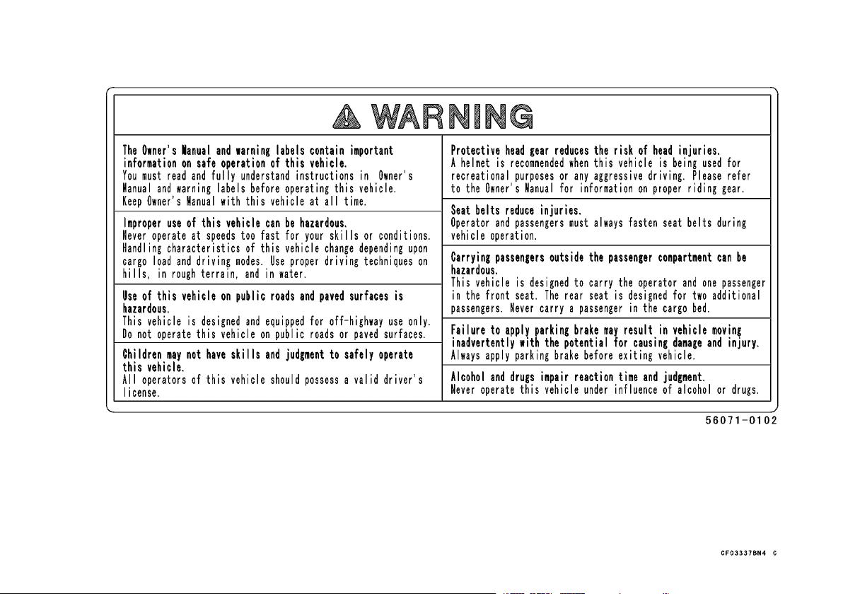
Off-Highway Use Only
This vehicle is not an al
signed and equipped to be a multiuse utility vehicle
for off-highway use only. Use of this vehicle on public roads and paved sur
operate this vehicle on public roads or paved surfaces.
Occupant Capacity
Make sure operators a
valid driver’s license.
Each occupant must be able to sit with back
against seat, feet fl
ing wheel, handgrip or handhold.
The operator should be tall enough to wear the
seat belt properly a
Passenger(s) should also be tall enough for the
seat belt to fit properly and to be able to brace the mselves, as necessar
the floor while gripping the handhold. Stay completely inside the vehicle.
Never Drink and Driv
Alcohol and drugs impair your judgement and slow
your reactions. Even drugs prescribed by a physician can be dangero
at on floor, and hands on steer-
nd reach all controls.
l-terrain vehicle; it is de-
faces is hazardous. Do not
re 16 years or older with a
y, by placing both feet firmly on
e
us. Ch eck with your doctor.

10 BASIC SAFE DRIVING
Protect Yourself, Us
As appropriate to your operating conditions, wear
approved helmet, eye protection, and protective
clothing. O peratin
driving or any aggressive riding, could increase the
risk of head injury, and thus require head protection.
In these conditions
operators and passengers wear a properly fitting
D.O.T. approved helmet. Wearing proper protective
gear can make drivi
reduce the severity of injury in the event of an accident.
Wearing Se at Belt
Both the operator and passenger(s) should always wear their seat belts properly. Seat belts
cannot completel
but in many cases a seat belt can reduce the risk
of serious injury. Also, to avoid injury, do not put
any part of your b
reason.
Before Startin g the Engine
Three “musts” be
1. Apply the parking b ra ke,
2. Put the gear shift lever in the “N” (neutral) posi-
tion,
e Proper Riding Gear
g in a recreational setting, like trail
, Kawasaki recommends that
ng more comfortable and could
y protect you in every accident,
ody outside of the vehicle for any
fore starting the engine are:
3. Check the throttle pe
should return to its rest position when released.
Use the Parking Brake
Always apply the parking brake before getting out
of your vehicle.
Obey Local Laws
Know and obey all laws and regulations governing the use of off-highway vehicles in your area. Respect private property. Always try to preserve nature
and the environment.
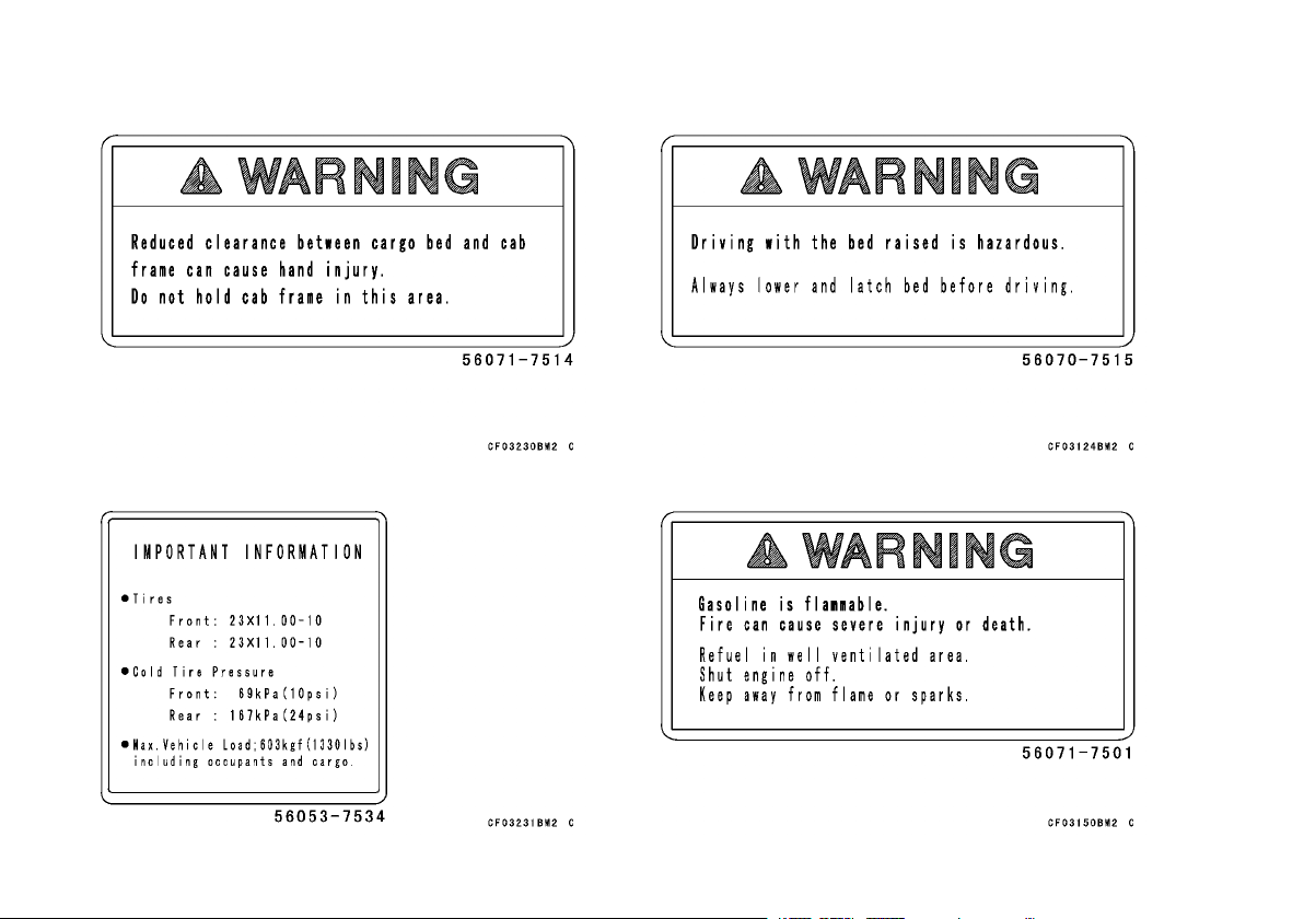
Refueling
Before refueling the vehicle, shut the engine off
and make sure the area is well ventilated and free
of any source of flame or sparks. Gasoline is very
flammable.
Tire Air Pressure
Tire inflation and type can affect the vehicle’s handling characteristics. Check the tire pressure frequently. Use only the recommended tires for replacement.
dal for proper operation. It

SPECIFICATIONS 11
SPECIFICATIONS
PERFORMANCE
Maximum Torque
Minimum Turning Radius Differential Mode: 3.9 m (12.80 ft)
Seating Capacity
DIMENSIONS
Overall Length 3 265 mm (128.54 in.)
Overall Width 1 485 mm (58.46 in.)
Overall Height 1 925 mm (75.79 in.)
Wheelbase
Tread: Front
Rear
Ground Clearance 180 mm (7.09 in.)
CurbMass 720kg(1588lb)
Cargo Bed (L × W × H) Long bed mode 1 280 × 1 210 × 285 mm (50.39 × 47.64
ENGINE
Type
Displacement
Bore × Stroke 76.0 × 68.0 mm (2.99 × 2.68 in.)
Compression Ratio
47.0N·m(4.8kgf·m,34.7ft·lb)@2500r/min(rpm)
Front 2 persons, Rear 2 persons
2 165 mm (85.24 in.)
1 160 mm (45.67 in.)
1 180 mm (46.46 in.)
× 11.22 in.)
Short bed mode 770 × 1
× 11.22 in.)
OHV, 2-cylinder, 4-stroke, liquid-cooled
617cm³(37.6cuin.)
10.3 : 1
210 × 285 mm (30.31 × 47.64

12 SPECIFICATIONS
Starting System
Cylinder Numbering Method
Firing Order
Carburetion System FI (Fuel Injection)
Ignition System
Ignition Timing
Spark Plug NGK BPR2ES
Lubrication Syste
Engine Oil: Grade API SG, SH, SJ, SL or
Coolant Capacity 4.6 L (4.9 US qt)
DRIVE TRAIN
Driving Type 4WD gear
Transmission Type
Primary Reduction Ratio
Final Reduction R
Overall Drive Ratio:
m
atio:
Viscosity
Capacity 1.8L(1.9USqt)
Front 5.200
Rear 5.429
Forward
Reverse 19.475
Electric starter
Front to rear, 1-2
1-2
Magneto and transistor
5° BTDC @750 r/min (rpm) ∼ 22° BTDC @4 000 r/min
(rpm)
Forced lubricatio
SAE 10W-40
2-speed & reverse, automatic
3.9 ∼ 0.85 (Belt drive torque converter)
8.404 (High)
17.303 (Low)
n (wet sump)
SM with JASO MA, MA1 or MA2

SPECIFICATIONS 13
Transmission Gear Ratio:
Front Final Gear Cas
Front Final Gear Case O il Capacity 0.4 L (0.4 US qt)
Transmission Case Oil API GL-5 Hypoid gear oil, SAE 90 [above 5°C (41°F)]
Transmission Case Oil Capacity 2.5 L (2.6 US qt)
FRAME
Type
Steering Assisted with Electric Power Steering (EPS) System
Caster 7.5°
Trail
Tire Size: Front & Rear
Rim Size: Front & Rear
Fuel Tank Capacity 24 L (6.3 US gal)
ELECTRICAL EQUIPMENT
Battery 12 V 14 A h
Headlight 12 V 35 W × 2
Tail/Brake Light 12 V 5/21 W × 2
eOil
Forward
Reverse 4.220
1.821 (High)
3.750 (Low)
API GL-5 or API GL-6 H
Differentials, SAE90 or SAE140
SAE 80 [below 5°C (41°F)]
Steel tube, ladder type
35 mm (1.4 in.)
23 × 11.00-10 Tubeless
10 × 8.5 AT
ypoid gear oil for Limited Slip

14 SPECIFICATIONS
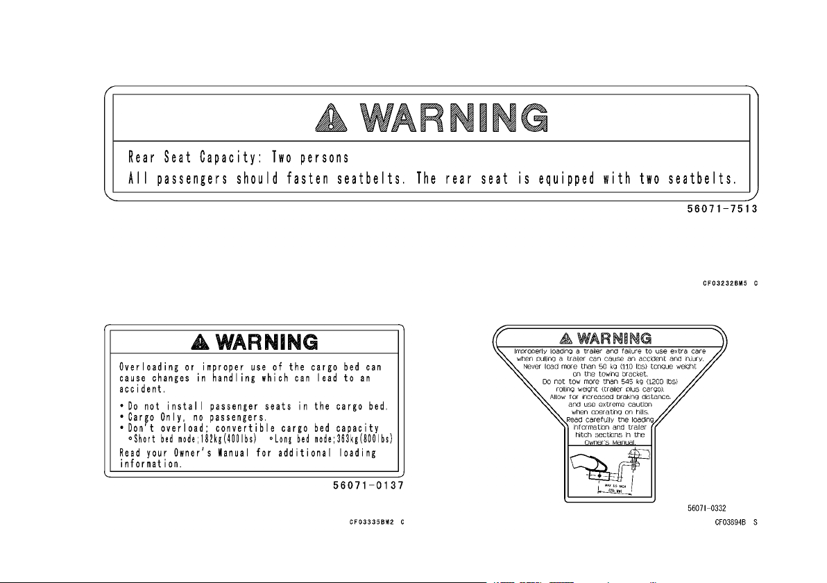
LOAD CAPACITY
Maximum Vehicle Load (Including occupants
and cargo)
Maximum Cargo Bed Lo
MODEL INFORMATION
MULE 4010 TRANS 4 × 4.......KAF620R/S
ad
603kg(1330lb)
Short Bed Mode: 182 k
Long Bed M ode: 363 kg
g (400 lb)
(800 lb)
NOTE
The KAF620S is identical to the KAF620R in every aspect: controls, features, and specifications except for
○
the camouflage surface treatment.
Specifications are subject to change without notice.
SERIAL NUMBER LOCATIONS 15
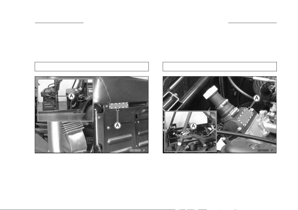
SERIAL NUMBER LOCATIONS
The engine and frame serial numbers are used to register the vehicle. They are the only means of identifying
your particular machine
dealer when ordering parts. In the event of theft, the investigating authorities will require both numbers as well
as the model type and any peculiar features of your machine that can help them identify it.
from others of the same m odel type. These serial numbers may be needed by your
Frame No.
A. Frame Number
Engine No.
A. Engine Number
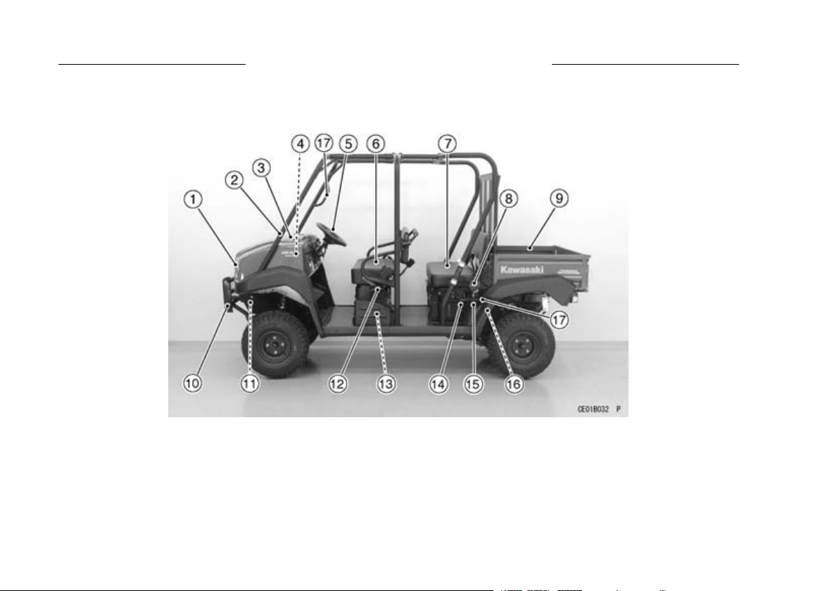
16 LOCATION OF PARTS
(Four-person mode)
LOCATION OF PARTS
1. Headlights
2. ROPS
3. Front Cargo
4. Front Cargo
5. Steering Wh
6. Front Seat
Hood
Compartment
eel
7. Rear Seat
8. Seat Belts
9. Cargo Bed
10. Front Bumpe
11. Radiator
12. Parking Bra
ke
13. Battery
14. Latch
r
15. Air Cleaner
Torque Conv
16. Belt Drive T
17. Handgrip
(Belt Drive
erter)
orque Converter
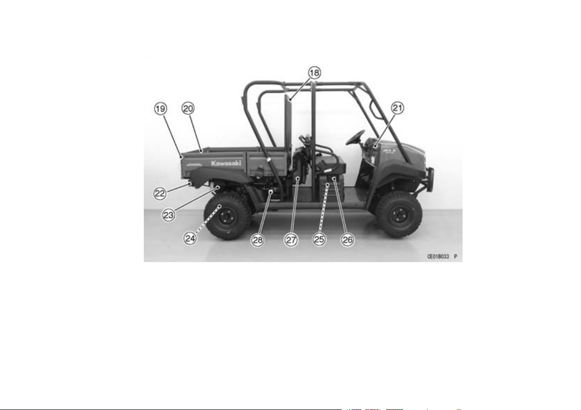
(Two-person mode)
LOCATION OF PARTS 17
18. Screen
19. Latch Handle
20. Tail Gate
21. Dashboard
22. Tail/Brake Lights
23. Muffler (Spark Arrester)
24. Trailer Hitch Bracket
25. Fuel Tank
26. Fuel Tank Cap
27. Rear Seat (folded)
28. Air Cleaner
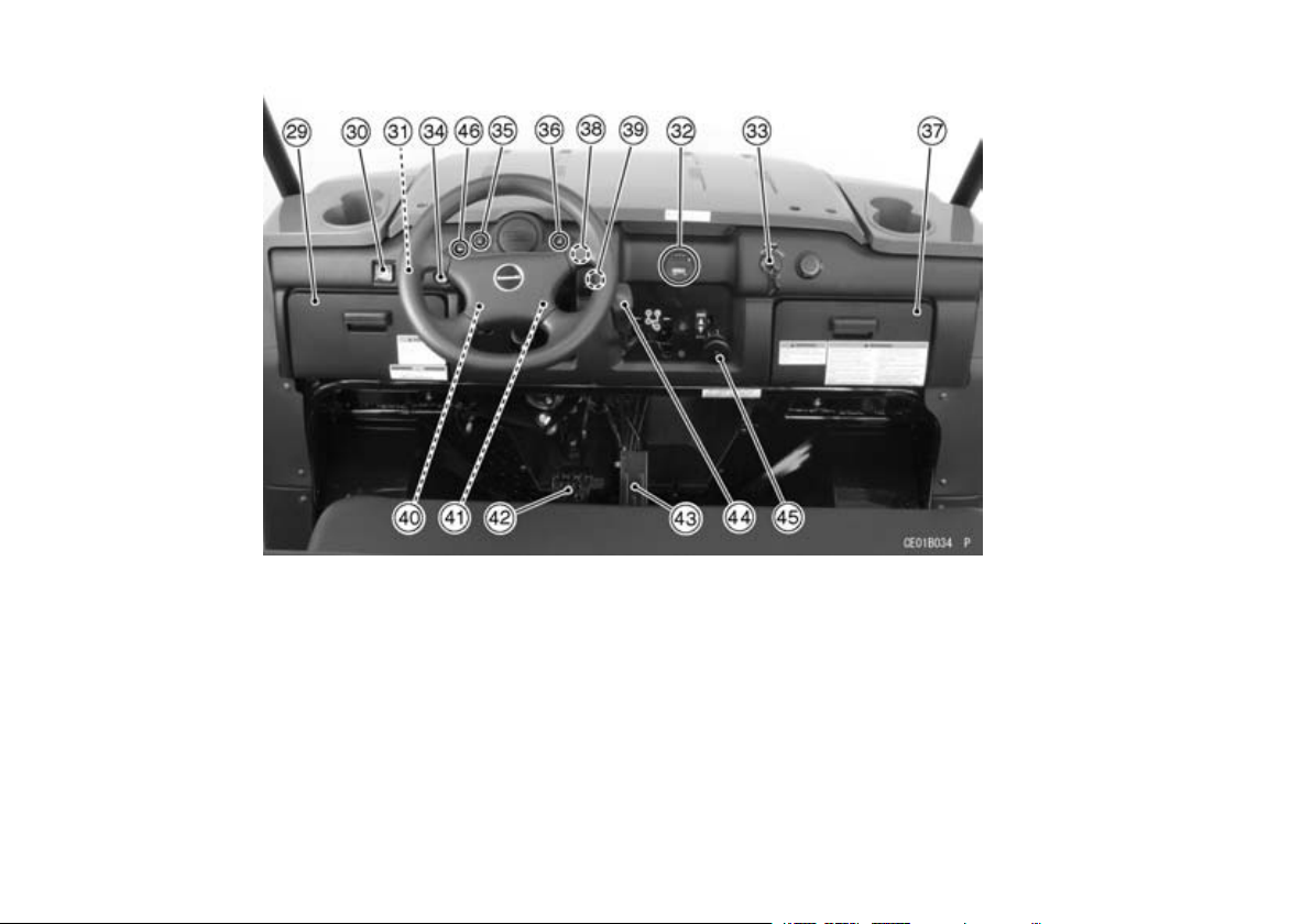
18 LOCATION OF PARTS
29. Left Glov
30. Light Swi
31. Horn Butt
32. Fuel Gau
33. Ignitio
34. Latch Re
35. Coolant
nSwitch
Warning
e Compartment
tch
on
ge/Hour Meter
lease Knob
Temperature
Light
36. Parking B
Light
37. Right Glo
38. FI Warni
39. Power St
Light
40. Differe
41. Brake Fl
ntial Shift Lever
rake Warning
ve Compartment
ng Light
eering Warning
uid Reserve Tank
42. Brake Ped
43. Throttle
44. Gear Shif
45. 2WD-4WD
46. Oil Pres
Pedal
sure Warning Light
al
t Lever
Shift Lever
LOCATION OF LABELS
All warning labels which are on your vehicle are
repeated here. Read la
derstand them thoroughly. They contain information
which is important for your safety and the safety of
anyone else who may op
fore, it is very important that all warning labels be on
your vehicle in the locations shown. If any label is
missing, damaged, o
your Kawasaki dealer and install it in the correct po sition.
The sample warning labels in this section have
○
part numbers to hel
the correct replacement.
Refer to the actual vehicle label for model specific
○
datagrayedoutin
bels on your vehicle and un-
erate your vehicle. There-
r worn, get a replacement from
NOTE
p you and your dealer obtain
the illustration.
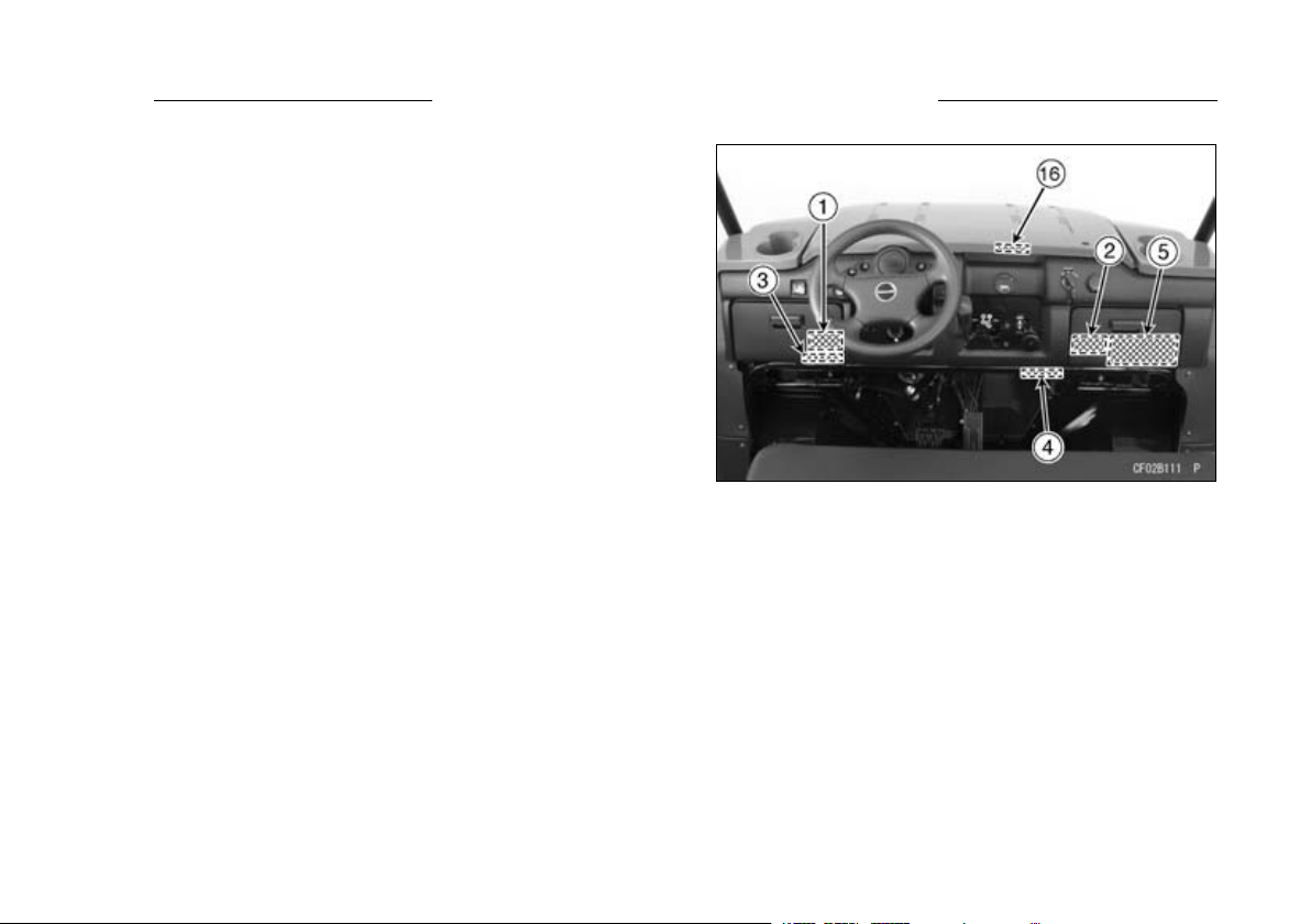
LOCATION OF LABELS 19
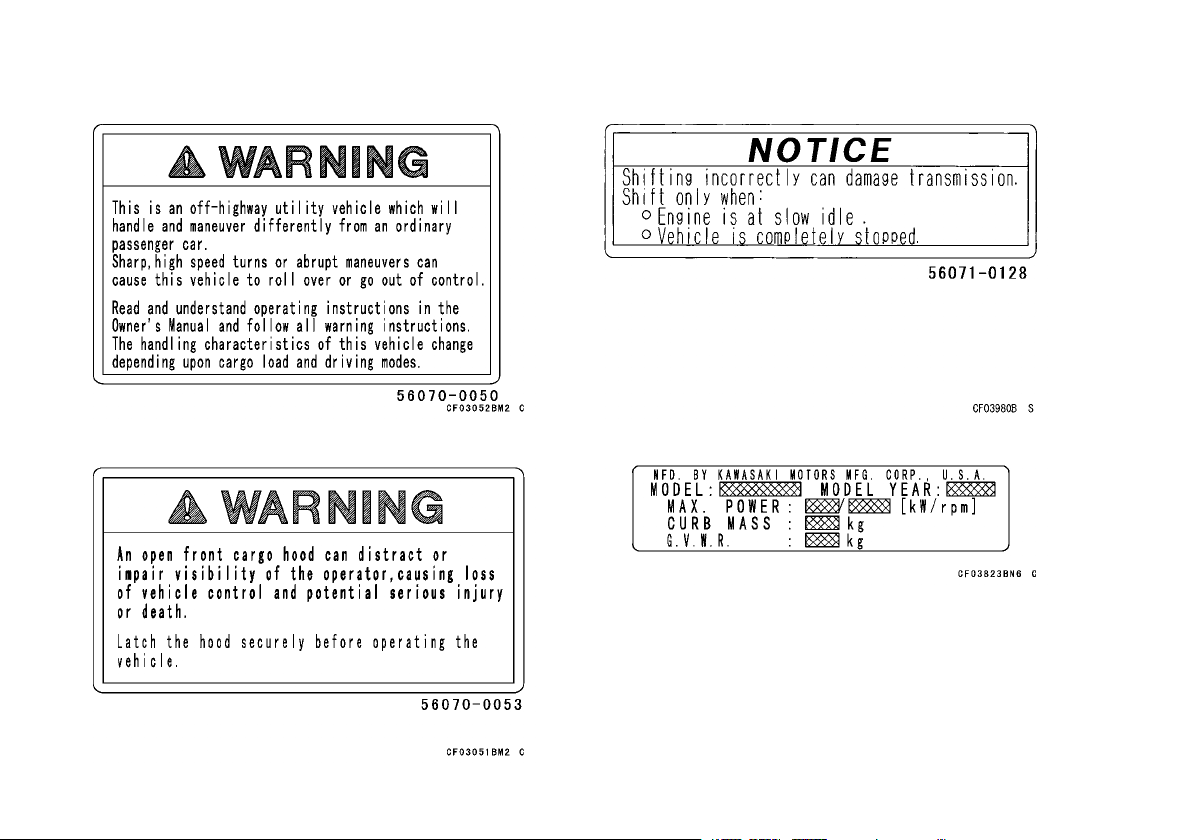
1. Warning (Off-Highway Utility Vehicle)
2. Warning (Front Cargo Hood)
3. Notice (Shifting)
4. Specification
5. Warning (General)
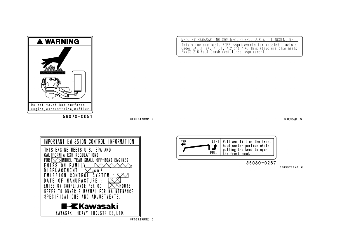
16. Information (Front Hood)
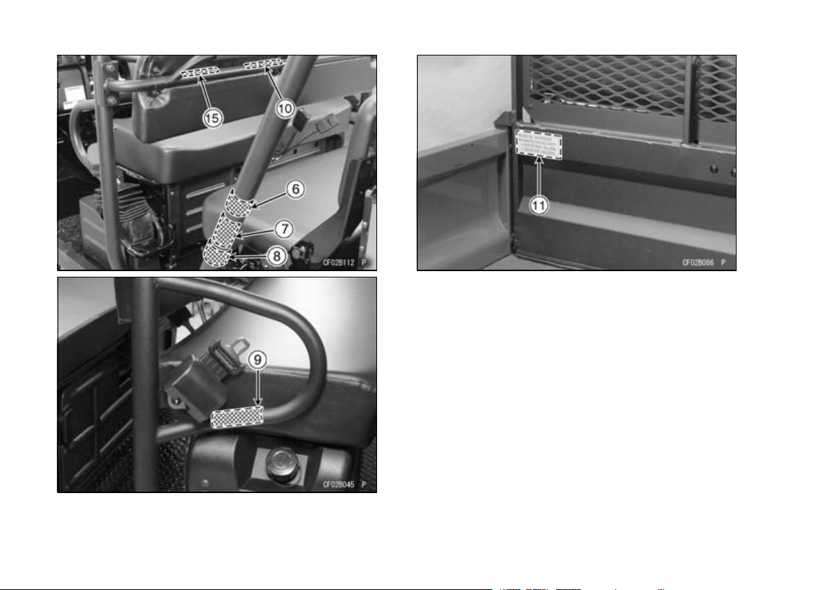
20 LOCATION OF LABELS
6. Warning (Pinching Fingers: both sides)
7. Important Information (Tires/Max. Load)
8.Warning(CargoBed)
9. Warning (Refueling)
10. Warning (Rear Seat Capacity)
11. Warning (Cargo Bed)
15. Specification
LOCATION OF LABELS 21
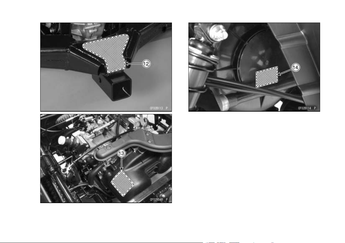
12. Warning (Trailer-Towing Bracket)
13. Warning (Hot Surfaces)
14. Important Engine Information
22 LOCATION OF LABELS
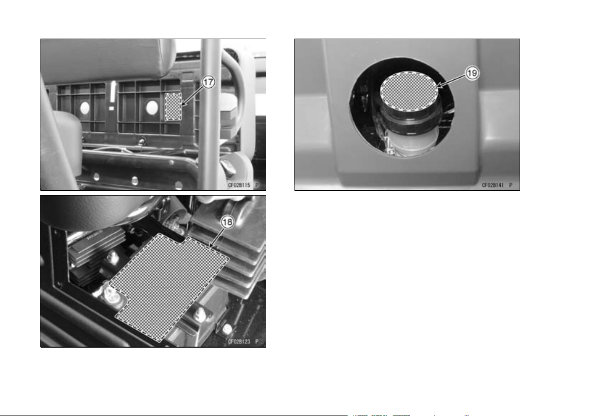
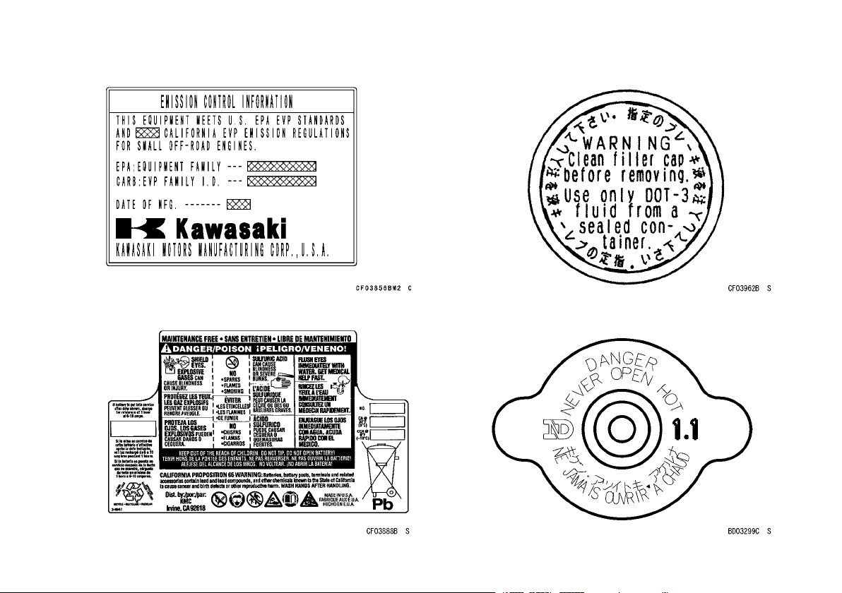
17. Important Emission Information
18. Battery Danger/Poison (On the backsid e)
19. Brake F luid
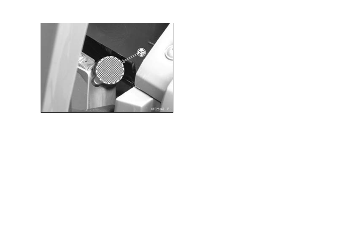
20. Radiator Cap Danger
LOCATION OF LABELS 23
24 LOCATION OF LABELS
(1)
(2)
(3)
(4)
(5)
LOCATION OF LABELS 25
26 LOCATION OF LABELS
(6)
(7)
(8)
(9)
(10)
(11) (12)
LOCATION OF LABELS 27
28 LOCATION OF LABELS
(13)
(14)
(15)
(16)
LOCATION OF LABELS 29
(17)
(18)
(19)
(20)
 Loading...