

Page 1
K
a
a
aw
s
k
Kawasaki Robotics (USA), Inc.
K
a
a
aw
s
k
D SERIES CONTROLLER
TROUBLESHOOTING AND
COMPONENT REPLACEMENT
MPVDCONTV113E-3
Page 2

This publication contains proprietary information of Kawasaki Robotics (USA), Inc. and
is furnished solely for customer use only. No other uses are authorized or permitted
without the express written permission of Kawasaki Robotics (USA), Inc. The contents
of this manual cannot be reproduced, nor transmitted by any means, e.g., mechanical,
electrical, photocopy, facsimile, or electronic data media, without the express written
permission of Kawasaki Robotics (USA), Inc.
All Rights Reserved.
Copyright © 2001, Kawasaki Robotics (USA), Inc.
Wixom, Michigan 48393
The descriptions and specifications in this manual were in effect when it was submitted
for publishing. Kawasaki Robotics (USA), Inc. reserves the right to change or discontinue specific robot models and associated hardware and software, designs, descriptions, specifications, or performance parameters at any time and without notice, without
incurring any obligation whatsoever.
This manual presents information specific to the robot model listed on the title page of
this document. Before performing maintenance, operation, or programming procedures,
all personnel are recommended to attend an approved Kawasaki Robotics (USA), Inc.
training course.
KAWASAKI ROBOTICS (USA), INC. TRAINING
Training courses covering operation, programming, electrical maintenance, and mechanical maintenance are available from Kawasaki Robotics (USA), Inc. These courses
are conducted at our training facility in Wixom, Michigan, or on-site at the customer’s
location.
For additional information contact:
Kawasaki Robotics (USA), Inc.
Training and Documentation Dept.
28059 Center Oaks Court
Wixom, Michigan 48393
Page 3
TROUBLESHOOTING AND COMPONENT REPLACEMENT
K
a
a
aw
s
k
noisiveR
rebmuN
esaeleR
etaDegnahCfonoitpircseDslaitinI
0-30/02/11ypoctnirpfo0-.veRnodesab,esaelerFDPlaitinIBC
/BC
1-40/72/4ypoctnirpfo1-.veRnodesab,1noisiveRBC/BC
3-50/60/9ypoctnirpfo3-.veRnodesab,3noisiveRBC/BC
REVISION HISTORY
D SERIES CONTROLLER
Page 4

D SERIES CONTROLLER
K
a
a
aw
s
k
TROUBLESHOOTING AND COMPONENT REPLACEMENT
TROUBLESHOOTING
1.0 TROUBLESHOOTING ................................................................................... 1-2
1.1 Error Recovery ............................................................................................... 1-2
1.2 Preliminary Troubleshooting ........................................................................... 1-5
1.2.1 Troubleshooting Common Failures ................................................................. 1-5
1.2.1.1 Controller Power Cannot Be Set to ON .......................................................... 1-6
1.2.1.2 Teach Pendant Is Inoperable ......................................................................... 1-8
1.2.1.3 Motor Power Cannot Be Enabled ................................................................. 1-10
1.2.1.4 Robot Does Not Move.................................................................................. 1-11
1.3 Error Codes ................................................................................................. 1-12
1.3.1 Error Display ................................................................................................ 1-13
1.3.2 Error List ...................................................................................................... 1-13
1.3.2.1 DXXXX Fatal Error Codes............................................................................ 1-14
1.3.2.2 EXXXX Non-Fatal Error Codes .................................................................... 1-59
1.3.2.3 PXXXX Operation Error Codes .................................................................. 1-159
1.3.2.4 WXXXX Mechanical/Control Warning Error Codes .................................... 1-200
1.4 Troubleshooting Flowcharts ....................................................................... 1-210
1-1August 9, 2005
Page 5

D SERIES CONTROLLER
K
a
a
aw
s
k
TROUBLESHOOTING AND COMPONENT REPLACEMENT
TROUBLESHOOTING
1.0 TROUBLESHOOTING
This unit provides error recovery flowcharts, error code information, and error code
troubleshooting flow charts. In addition, typical causes and remedies for the errors are
also provided.
1.1 ERROR RECOVERY
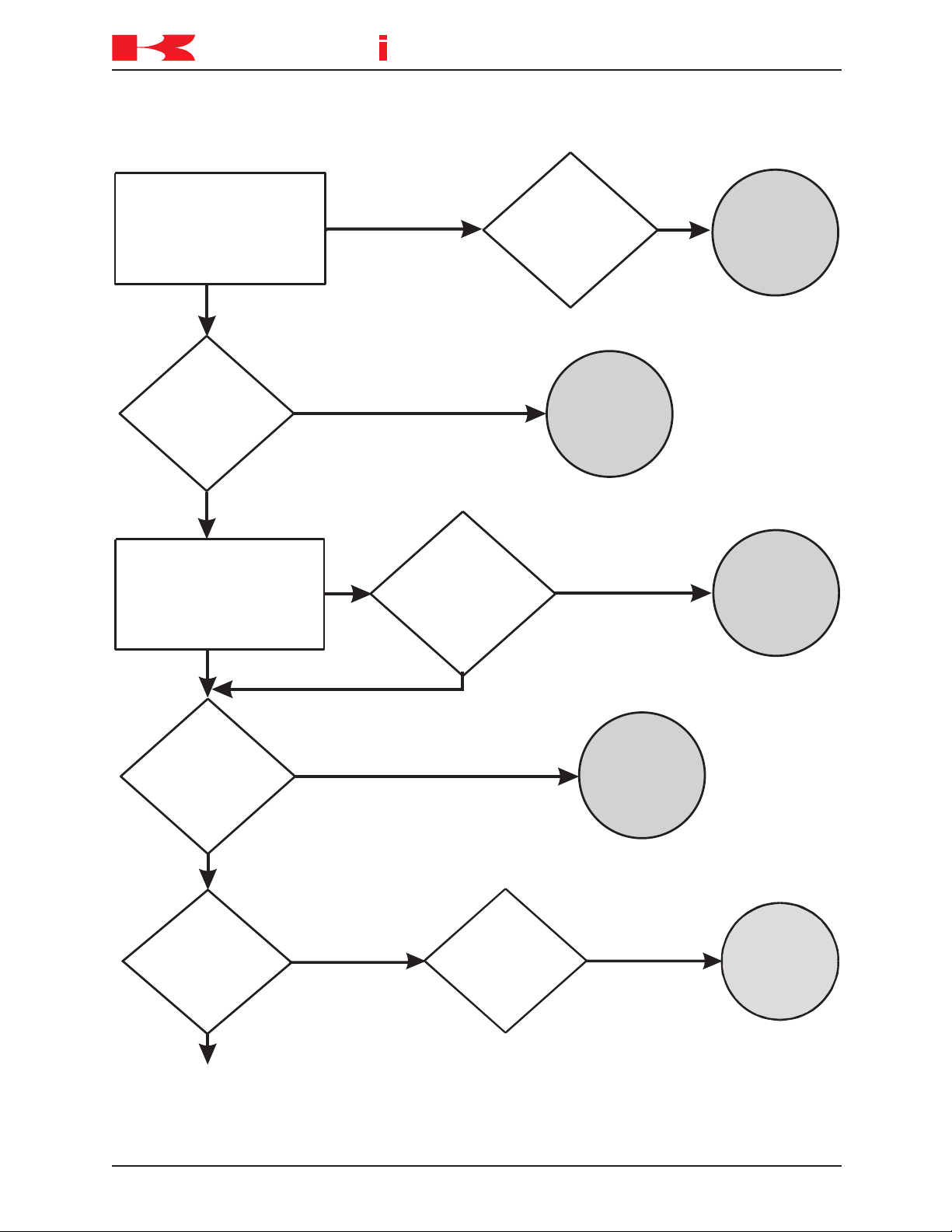
Figures 1-1 and 1-2 show troubleshooting processes that may be helpful if the controller
becomes unresponsive to commands or an error code has been encountered that
cannot be cleared. Troubleshooting should begin with confirmation of basic integrity of
the system: ensure that the power supply is on and meeting supply requirements, all
cables are correctly attached, all circuit boards are properly installed and fully seated, all
peripheral equipment is wired correctly, software is properly configured, etc.
1-2 August 9, 2005
Page 6
TROUBLESHOOTING AND COMPONENT REPLACEMENT
K
a
a
aw
s
k
Source of error known
Locate error on the error
table and determine the
characteristics and possible
causes of the error
Source of error unknown
Press the yellow
reset button on the
controller panel
Error will not clear or
machine is in a “locked” mode
Error cleared and robot
runs normally
Error clears and robot
runs normally
to monitor
and continue
Run Program
Run Program
and continue
to monitor
Troubleshoot
and correct
source of
error
Ye s
Ensure the robot
system data, all
components, signals,
and programs are
compatible
agrees with program, etc.
removed, signal interface
components added or
internal parts, interface
made to system? New
beenchangesanyHave
No
Cycle the
controller power
OFF and ON
Run Program
and continue
to monitor
Error or “locked”
condition cleared
Error still present
Continued on next page
to monitor
and continue
Run Program
Create
backup information
files and initialize the
system
Run program
and continue
to monitor
Error or “locked”
condition cleared
Reset
system settings not
set to defaults after
initialization
TROUBLESHOOTING
D SERIES CONTROLLER
Figure 1-1 Troubleshooting Process
1-3August 9, 2005
Page 7
TROUBLESHOOTING AND COMPONENT REPLACEMENT
K
a
a
aw
s
k
Continued from previous pg
Error still present
Remove the
1KA board from the
rack and allow RAM
memory to deplete
Reinstall
1KA board,
initialize the
system, zero
Error clears and robot
runs normally
Run program
and continue
to monitor
Begin electrical
troubleshooting and repair if
qualified; call service
technician for further
assistance
TROUBLESHOOTING
D SERIES CONTROLLER
Figure 1-2 Troubleshooting Process (Continued)
1-4 August 9, 2005
Page 8

D SERIES CONTROLLER
K
a
a
aw
s
k
TROUBLESHOOTING AND COMPONENT REPLACEMENT
TROUBLESHOOTING
1.2 PRELIMINARY TROUBLESHOOTING
Prior to following error code troubleshooting procedures, ensure preliminary troubleshooting steps are completed.
1. Ensure proper 460 VAC three-phase power is available at the input and output side
of the controller main disconnect (circuit breaker F1).
2. Ensure circuit breakers F2, F3, F4, and F5 are
3. Ensure proper +5 VDC, +12 VDC, -12 VDC and +24 VDC are available from the
AVR power supply.
4. Observe the state of LEDs and refer to the appropriate section of the
Controller Electrical Maintenance Manual
these conditions are
5. Check for loose connection at circuits boards and cable connections.
6. Ensure all circuit boards are properly seated in the card rack (where applicable).
7. Ensure the F1 and F2 fuses on the 1KP board are
1.2.1 TROUBLESHOOTING COMMON FAILURES
This section describes some common failures, possible causes, and corrective actions.
1.2.1.1 Controller Power Cannot Be Set ON
not normal, correct the cause of abnormal LED indications.
for conditions indicated by the LEDs. If
not tripped.
D Series
not open.
1.2.1.2 Teach Pendant is Inoperable
1.2.1.3 Motor Power Cannot Be Set ON
1.2.1.4 Robot Does Not Move
1-5August 9, 2005
Page 9

D SERIES CONTROLLER
K
a
a
aw
s
k
TROUBLESHOOTING AND COMPONENT REPLACEMENT
TROUBLESHOOTING
1.2.1.1 CONTROLLER POWER CANNOT BE SET TO ON
This failure occurs when the controller does not power-up when the controller main
disconnect is set to ON.
Failure 1: When the controller main disconnect is set to ON, circuit breaker F1 is tripped
immediately.
Main causes include:
1. The AC power line is short-circuited in the controller, and circuit breaker F1 detects
overcurrent and is tripped.
2. Defective F1 circuit breaker.
⇒
Interrupt the 460 VAC to the main disconnect (circuit breaker F1) set the controller
main disconnect to ON. Using an ohm meter check for a short circuit between these
points:
R and S, S and T, T and R, R and FG, S and FG, T and FG (FG=frame ground)
If a short circuit is detected replace components as necessary (wiring, transformer
T1, circuit breaker F1, etc.).
Failure 2: When the main disconnect is set to ON, the control power lamp does not
illuminate (circuit breaker F1 does not trip).
This failure occurs when the controller does not activate properly because of an abnormality in the primary power supplied to the controller or in the power supply circuit in the
controller.
Main causes include:
1. The primary power voltage supplied to the controller is not within specifications, the
primary power cable is disconnected or damaged, or the primary power is not
supplied.
2. Power is not supplied to the 1KQ/1NR board, or the 1KQ/1NR board is defective.
3. Power is not supplied to the AVR power supply.
4. Power is not supplied to the control power lamp due to a defective AVR power
supply, 1KX/1NR board, 1LS/1NS board or control power lamp.
5. Disconnected or short-circuited wiring in the controller.
1-6 August 9, 2005
Page 10

D SERIES CONTROLLER
K
a
a
aw
s
k
TROUBLESHOOTING AND COMPONENT REPLACEMENT
TROUBLESHOOTING
⇒
Ensure primary power supply is within specifications. Ensure primary power supply
cable is properly connected and is not damaged.
⇒
Ensure connectors at the 1KQ/1NR board are properly installed and not damaged.
⇒
Ensure the 1KP board fuses F1 and F2 are not open.
⇒
Replace the 1KQ/1NR board.
⇒
Ensure the power supplied to the AVR power supply is within specifications. Ensure
the power connector at the AVR power supply is properly connected and not damaged.
⇒
Ensure to output voltages from the AVR power supply are within specifications.
⇒
Ensure the control power lamp is properly installed and is not defective.
⇒
Repair or replace disconnected or short-circuited wiring in the controller.
1-7August 9, 2005
Page 11

D SERIES CONTROLLER
K
a
a
aw
s
k
TROUBLESHOOTING AND COMPONENT REPLACEMENT
TROUBLESHOOTING
1.2.1.2 TEACH PENDANT IS INOPERABLE
The teach pendant is in operable with the controller main disconnect set to ON and the
control power lamp is illuminated.
Failure 1: The control power lamp is illuminated and the teach pendant is inoperable
(the back light is not illuminated).
DC power is supplied to the controller, but power is not supplied to the teach pendant to
illuminate the display or back light.
Main causes include:
1. +12 VDC is not supplied to the teach pendant.
2. Defective LCD panel, circuit board, or other internal teach pendant components.
3. Disconnected or short-circuited teach pendant cable.
⇒
Ensure the teach pendant cable is properly connected to the controller.
⇒
Replace the teach pendant.
⇒
Replace the teach pendant cable.
Failure 2: The back light is illuminated, but the screen is not displayed.
When the teach pendant back light is illuminated this indicates power is supplied to the
teach pendant. If the teach pendant is operating normally the initial screen is displayed
regardless of the 1KA board condition.
Main causes include:
1. Defective LCD panel, circuit board, or other internal teach pendant components.
⇒
Replace the teach pendant.
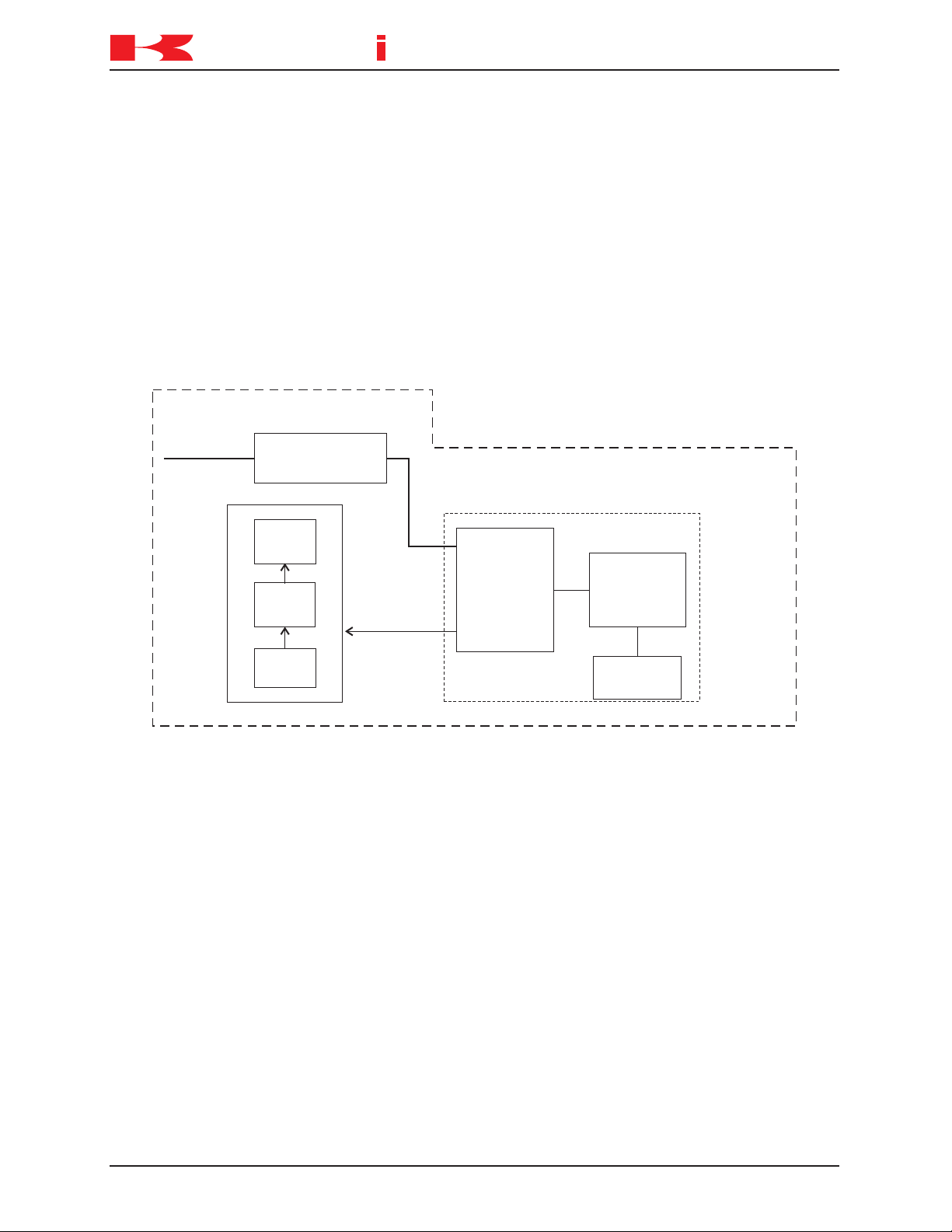
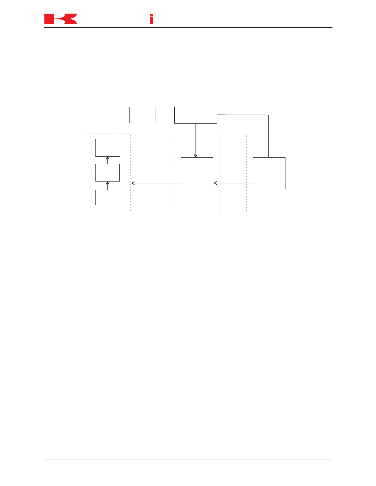
Failure 3: The teach pendant screen is displayed and the back light is illuminated, but
key input and AS Language commands are not possible.
This condition occurs when key input and AS Language commands do not reach the
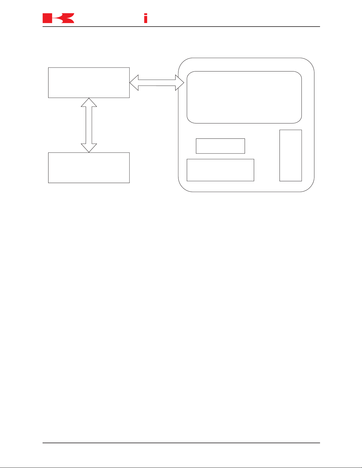
1KA board or data from the 1KA board does not reach the teach pendant.
Data is transmitted between the 1KA board and the teach pendant as shown in figure 1-
3.
1-8 August 9, 2005
Page 12
TROUBLESHOOTING AND COMPONENT REPLACEMENT
K
a
a
aw
s
k
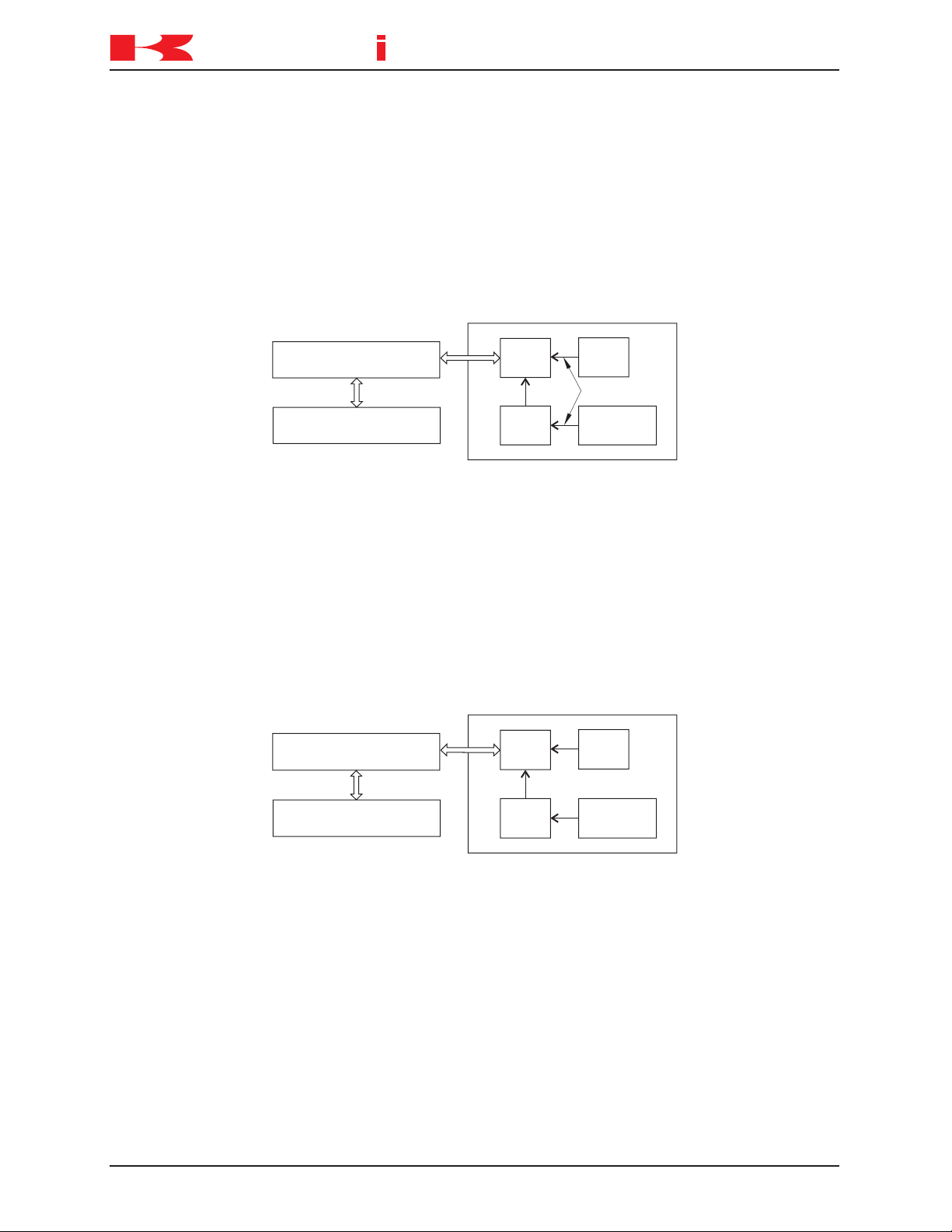
1KX/1NX Mother Board
1KA Main CPU Board
Display Device
Teach Pendant
Input
Keys
TROUBLESHOOTING
D SERIES CONTROLLER
Main causes include:
1. Interruption in data communication between the teach pendant and the 1KA board.
2. Defective LCD panel, circuit board, or other internal teach pendant components.
3. Defective 1KA or 1KX/1NX boards.
4. Disconnected or short-circuited teach pendant cable.
⇒
Ensure the teach pendant cable is properly connected to the controller.
⇒
Replace the teach pendant cable.
⇒
Replace the teach pendant.
⇒
Replace the 1KA or 1KX/1NX boards.
Figure 1-3 1KA/Teach Pendant Communication
1-9August 9, 2005
Page 13

D SERIES CONTROLLER
K
a
a
aw
s
k
TROUBLESHOOTING AND COMPONENT REPLACEMENT
TROUBLESHOOTING
1.2.1.3 MOTOR POWER CANNOT BE ENABLED
This condition exists when motor power does not engage when the MOTOR POWER
switch is pressed.
Main causes include:
1. An error condition exists.
2. K1, K2, or K3 are not engaged due to a defective 1KQ/1NR board, MC unit, teach
pendant, software, eternal signals etc.
3. Emergency stop condition exists.
4. Defective power block.
5. Disconnected or short-circuited motor power supply harness.
6. Motor temperature or controller internal temperature exceeds limits
⇒
If the operation panel error lamp is illuminated or an error message is displayed on
the teach pendant LCD, take appropriate measures to release the error condition
according to the error message.
⇒
Check and repair any abnormalities in the motor power supply circuit.
⇒
Ensure all EMERGENCY STOP switches are released.
⇒
Replace the power block.
⇒
Replace the motor power supply harness.
⇒
Ensure motor temperature and controller internal temperature does not exceed limits.
1-10 August 9, 2005
Page 14

D SERIES CONTROLLER
K
a
a
aw
s
k
! WARNING
TROUBLESHOOTING AND COMPONENT REPLACEMENT
TROUBLESHOOTING
1.2.1.4 ROBOT DOES NOT MOVE
This condition exists when the robot does not move when conditions are set for teach or
repeat mode.
Main causes include:
1. External hold condition exists.
2. An error condition exists.
3. Operation panel switches set incorrectly.
4. Motor brakes are not released.
5. If the check mode is selected, ensure an enabling device is engaged and the GO
(step forward) key is pressed.
6. Robot is waiting for input signals in repeat mode (cycle start, step forward, program
change, WX, JUMP, etc.)
⇒
Release external hold condition.
⇒
If the operation panel error lamp is illuminated or an error message is displayed on
the teach pendant LCD, take appropriate measures to release the error condition
according to the error message.
⇒
Ensure the operation panel switches are set correctly for robot operation.
⇒
Ensure proper brake voltage is available to the brake release circuit. Check and
repair poor connections, disconnected connectors, open wiring, short circuited wiring,
or any abnormalities in the brake circuits. Ensure the 1KP board, 1KQ/1NR board,
AVR power supply, MC unit, 1KQ/1NR board, servo motor, and controller internal
brake harnesses are in serviceable condition.
⇒
When check mode is selected, ensure an enabling device is engaged and the GO
(step forward) key is pressed.
⇒
In repeat mode, ensure input signals are received to release a wait condition.
The robot may move suddenly when a wait condition is
released. Do not approach the robot when it appears to
be stopped.
1-11August 9, 2005
Page 15
D SERIES CONTROLLER
K
a
a
aw
s
k
edoCgoLrorrEnoitpircseDtnemmoC
DrorrelataF .rorreecivedlarehpirepro,erawtfos,erawdraH
ebtsumrewoplortnocdet
cerrocsirorrenehW
.NOdnaFFOdelcyc
Erorrelataf-noN.teserrorresserp,detcerrocsirorrenehW
ProrrenoitarepO.noito
mtobortceffatonseoD
Wgninrawlortnoc/lacinahceM.detcerroctonfirorrenaesuacyaM
epyTrorrEpmaLrorrEpmaLtratSelcyCrewoProtoM
PFFONONO
W
1
FFOroNO
1
FFOroNO
1
FFOroNO
ENOFFO
1
FFOroNO
DNOFFOFFO
1
tnetnocrorreehtnognidnepeD
TROUBLESHOOTING AND COMPONENT REPLACEMENT
TROUBLESHOOTING
1.3 ERROR CODES
This unit provides information about the error codes that are displayed on the teach
pendant or other user interfaces that provide display screen information. The error
codes are listed in numerical order by prefix and code number with the message that is
displayed on the teach pendant. An expanded explanation of the message is provided
along with possible methods to clear or prevent the specific error. Troubleshooting
information is preceded by an ⇒
symbol.
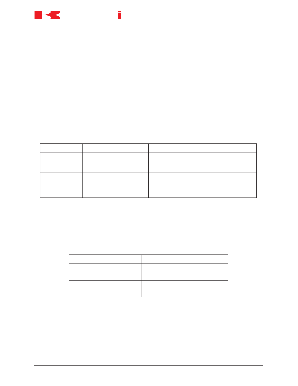
Table 1-1 provides an explanation of the error code prefixes.
Table 1-1 Error Code Prefix Descriptions
Table 1-2 describes the controller state for each type of error.
Table 1-2 Controller Error State
1-12 August 9, 2005
Page 16
D SERIES CONTROLLER
K
a
a
aw
s
k
Pro ramg
[Comment ]
Step
PC
Status
03-01-31 11:55
90%
RPS
Pro ram aborted. No = 1g
Error
p6g
[
1
[
]
0.000 0.000 0.000 0.000 0.000 0.000
JT 1 JT 2 JT 3 JT 4 JT 5 JT 6
(E0100) 02-11-08(Fri) 16:33:20
Abnormal comment statement exists.
T
C
R
]
!
1 pcpr 1g
Reset
Close
JOINT
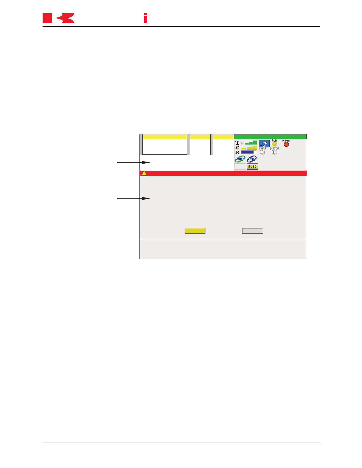
System Message Area
Error Pop-up Screen
TROUBLESHOOTING AND COMPONENT REPLACEMENT
TROUBLESHOOTING
1.3.1 ERROR DISPLAY
Error messages are displayed on the teach pendant LCD screen and/or a PC interfaced
with the controller using KRterm/KCWIN32 terminal software.
The teach pendant LCD screen displays operation errors (P errors) in the system message area and other error messages are shown in a pop-up screen display (Figure 1-4).
1.3.2 ERROR LIST
Refer to the following sections for errors and descriptions:
1.3.2.1 DXXXX Fatal Error Codes
1.3.2.2 EXXXX Non-Fatal Error Codes
1.3.2.3 PXXXX Operation Error Codes
1.3.2.4 WXXXX Mechanical/Control Warning Error Codes
Figure 1-4 Teach Pendant Error Screen Display
1-13August 9, 2005
Page 17
D SERIES CONTROLLER
K
a
a
aw
s
k
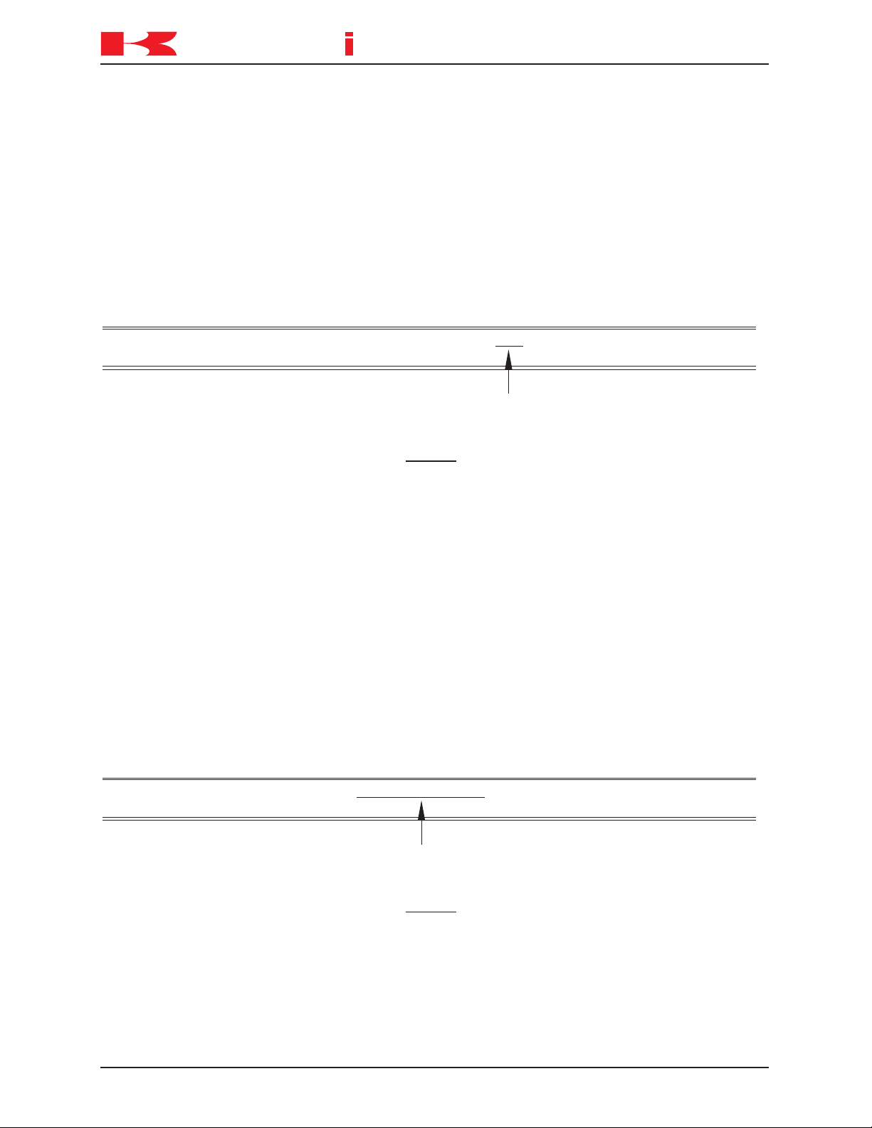
PC Error Display Example:
Error (D0001) CPU error Code=1
Task (Pc01) Stop SIG=00070004 [FAULT (PARALLEL)] PC=*****
Indicates the place the error occurred
PC Error Display Example:
Error (D0002) CPU BUS error Code=1
Task (Pc01) Stop SIG=00070004 [NMI ] PC=*****(VME BUS ERROR)
Indicates the place the error occurred
TROUBLESHOOTING AND COMPONENT REPLACEMENT
TROUBLESHOOTING
1.3.2.1 DXXXX FATAL ERROR CODES
ERROR CODE D0001 CPU Error. (PC=XX)
The 1KA board CPU has stopped (detected by the AS software). This error is caused
by defective AS or servo software, defective hardware, or noise related malfunction.
⇒
Refer to the error message displayed on a PC interfaced with the controller.
⇒
Cycle controller power OFF and ON. Do not initialize the controller. If a message for
initialization is displayed, select “NO”.
⇒
If the error does not reset when power is cycled, initialize the system and reload
program data.
⇒
Replace the 1KA board.
⇒
If the above steps do not correct the error, contact KRI customer service
_____________________________________________________________________
.
ERROR CODE D0002 Main CPU BUS error. (PC=XX)
A 1KA board bus error occurs (in the VME bus line, detected by AS software); data
processing is not completed normally. This error is caused by defective AS software,
defective 1KA board, or noise related malfunction.
⇒
Refer to the error message displayed on a PC interfaced with the controller.
⇒
Cycle controller power OFF and ON. Do not initialize the controller. If a message for
initialization is displayed, select “NO”.
⇒
If the error does not reset when power is cycled, initialize the system and reload
program data.
⇒
Replace the 1KA board.
⇒
If the above steps do not correct the error, contact KRI customer service
_____________________________________________________________________
.
1-14 August 9, 2005
Page 18
D SERIES CONTROLLER
K
a
a
aw
s
k
PC Error Display Example:
Error (D0003) VME bus error Code=1
Task (Pc01) Stop SIG=00070004 [NMI(VME BUS ERROR)] PC=*****
bus-read= bus-write=******** *********
Indicates the place the error occurred
PC Error Display Example:
Error (D0004) [ARM CONTROL BOARD] CPU error Code=1
Task (Pc01) Stop SIG=00070004 [FAULT (PARALLEL)] PC=*****
Indicates the place the error occurred
TROUBLESHOOTING AND COMPONENT REPLACEMENT
TROUBLESHOOTING
ERROR CODE D0003 VME BUS error. (PC=XX)
This error occurs when the CPU does not receive a response from one of the I/O bus
devices within a specific time. This error is caused by defective AS software, defective
1KA board, or noise related malfunction.
⇒
Refer to the error message displayed on a PC interfaced with the controller.
⇒
Cycle controller power OFF and ON. Do not initialize the controller. If a message for
initialization is displayed, select “NO”.
⇒
If the error does not reset when power is cycled, initialize the system and reload
program data.
⇒
Replace the 1KA board.
⇒
If the above steps do not correct the error, contact KRI customer service
_____________________________________________________________________
.
ERROR CODE D0004 [ARM CONTROL BOARD] CPU error. (PC=XX)
The 1KB board CPU is stopped (detected by the AS software). This error is caused by
defective AS or servo software, defective hardware, or noise related malfunction.
⇒
Refer to the error message displayed on a PC interfaced with the controller.
⇒
Cycle controller power OFF and ON. Do not initialize the controller. If a message for
initialization is displayed, select “NO”.
⇒
Ensure the correct 1KB board software is loaded into the 1KA board.
⇒
Replace the 1KB board.
⇒
If the above steps do not correct the error, contact KRI customer service
_____________________________________________________________________
.
1-15August 9, 2005
Page 19
D SERIES CONTROLLER
K
a
a
aw
s
k
PC Error Display Example:
Error (D0005) [ARM CONTROL BOARD] CPU BUS error Code=1
Task (Pc01) Stop SIG=00070004 [NMI( )] PC=*****VME BUS ERROR
Indicates the place the error occurred
TROUBLESHOOTING AND COMPONENT REPLACEMENT
TROUBLESHOOTING
ERROR CODE D0005 [ARM CONTROL BOARD] CPU BUS error. (PC=XX)
On the 1KB board, a bus error occurs (in the VME bus line, detected by AS software);
data processing is not completed normally. This error is caused by defective AS software, defective 1KB board, or noise related malfunction.
⇒
Refer to the error message displayed on a PC interfaced with the controller.
⇒
Cycle controller power OFF and ON. Do not initialize the controller. If a message for
initialization is displayed, select “NO”.
⇒
Ensure the correct 1KB board software is loaded into the 1KA board.
⇒
Replace the 1KB board.
⇒
If the above steps do not correct the error, contact KRI customer service
_____________________________________________________________________
.
ERROR CODE D0900 Teach data is broken.
The program storage area of the system memory is damaged and is not linking data
correctly.
Main causes include:
1. Loss of memory battery back-up.
2. Noise related malfunction.
3. Defective 1KA board.
⇒
Set the 1KA board switch SW2-8 to ON and initialize the memory, do not use AUX
0805 or SYSINIT command. Reload the robot program data.
⇒
Check the memory backup battery. Replace if necessary (3.3 VDC or less). When
battery voltage drops to 3.3 VDC, or less, error W1010 is displayed.
⇒
Replace the 1KA board if the error recurs.
_____________________________________________________________________
1-16 August 9, 2005
Page 20

D SERIES CONTROLLER
K
a
a
aw
s
k
TROUBLESHOOTING AND COMPONENT REPLACEMENT
TROUBLESHOOTING
ERROR CODE D0901 AS Flash memory sum check error.
A check sum error occurrs in AS software, in flash memory on the 1KA board, when the
controller is powered-up. The check sum data is created when the FCHK command is
executed and is recorded in flash memory during AS software download.
Main causes include:
1. When the AS software is downloaded, the FCHK command is not executed.
2. The addressing of the FCHK command is wrong.
3. The flash memory and 1KA board are defective.
4. The system data in the flash memory is corrupt.
⇒
Confirm the content of the command as_load.cmd file on the PC card. If error occurs
immediately after downloading the AS software, download AS software again. If error
continues after download, replace the 1KA board.
_____________________________________________________________________
ERROR CODE D0902 Servo flash memory sum check error.
A check sum error of the servo software in flash memory on the 1KA board occurrs
when the controller is powered-up. The check sum data is created when the FCHK
command is executed and is recorded in flash memory during software download.
Main causes include:
1. When the servo software is downloaded, the FCHK command is not executed.
2. The addressing of the FCHK command is wrong.
3. The flash memory and 1KA board are defective.
4. The system data in flash memory is corrupt.
⇒
If the error occurs immediately after servo software download, confirm the content of
sv_load.cmd on the PC card and download servo software again. If the error reoccurs, replace the 1KA board.
_____________________________________________________________________
ERROR CODE D0903 IP board memory error. (Code)
This error occurs when the flash ROM on the 1GS board is corrupt (check sum error).
Code 2: flash ROM SAM error.
Code 3: DPRAM write and read error.
Code 4: SRAM write and read error.
⇒
Replace the 1GS board.
_____________________________________________________________________
1-17August 9, 2005
Page 21

D SERIES CONTROLLER
K
a
a
aw
s
k
TROUBLESHOOTING AND COMPONENT REPLACEMENT
TROUBLESHOOTING
ERROR CODE D0904 Memory is locked due to AC_FAIL.
The memory is accessed during the controller shut down due to a power supply abnormality (ACFAIL) (AVR +5 V, +12 V, -12 V, +24 V).
⇒
Cycle the controller power OFF and ON.
⇒
Check for proper AVR voltage supply (+5 V, +12 V, -12 V, +24 V) and related circuitry.
_____________________________________________________________________
ERROR CODE D1000 Read error of servo control software.
Main causes include:
1. Servo control software (armsc.mb) not found at controller power-up or software is
corrupt.
2. Defective 1KJ/1QJ board.
⇒
Download servo control software (armsc.mb)
Replace 1KJ/1QJ board.
⇒
_____________________________________________________________________
ERROR CODE D1001 Download error of servo control software.
Servo control software (armsc.mb) download failure at controller power-up.
Main causes include:
1. Incorrect servo control software.
2. Defective 1KJ/1QJ board.
2. Defective 1KA and or 1KB board.
⇒
Ensure the correct servo software is loaded into the 1KA board
⇒
Replace the 1KJ/1QJ board.
⇒
Replace the 1KA and or 1KB board.
_____________________________________________________________________
.
.
1-18 August 9, 2005
Page 22

TROUBLESHOOTING AND COMPONENT REPLACEMENT
K
a
a
aw
s
k
TROUBLESHOOTING
ERROR CODE D1002 Init. error of servo software.
D SERIES CONTROLLER
Servo software
Main causes include:
1. Servo software is not installed correctly or is corrupt.
2. Incompatibility between the AS and servo software.
3. Defective 1KA and or 1KB board.
⇒
Reinstall servo software.
⇒
Check compatibility of AS and servo software and reinstall software as needed.
⇒
Replace the 1KA and or 1KB boards.
_____________________________________________________________________
ERROR CODE D1003 Init. error of servo control software.
Servo software
Main causes include:
1. Servo software is not installed correctly or is corrupt.
2. Incompatibility between the AS and servo software.
3. Defective 1KA and or 1KB board.
(armsc.mb)
(armsv.abs)
initialization failure at controller power-up.
initialization failure at controller power-up.
⇒
Reinstall servo software.
⇒
Check compatibility of AS and servo software and reinstall software as needed.
⇒
Replace the 1KA and or 1KB boards.
_____________________________________________________________________
1-19August 9, 2005
Page 23
D SERIES CONTROLLER
K
a
a
aw
s
k
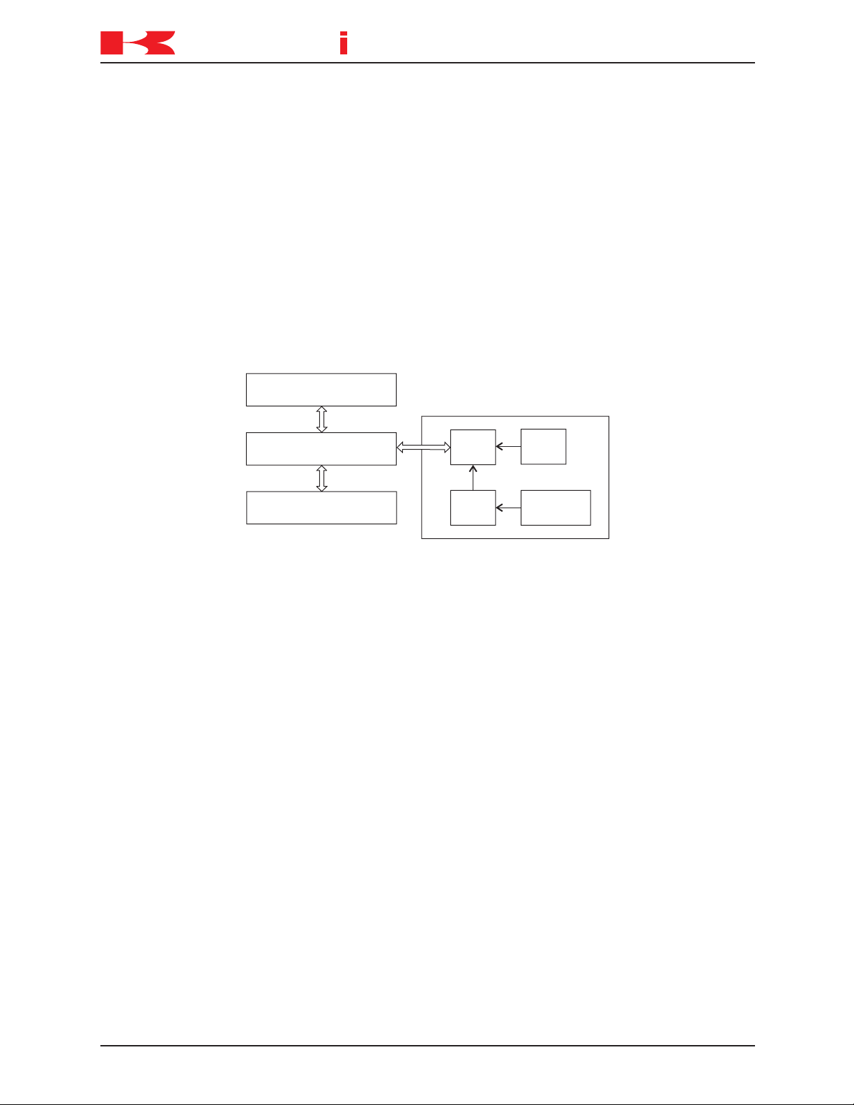
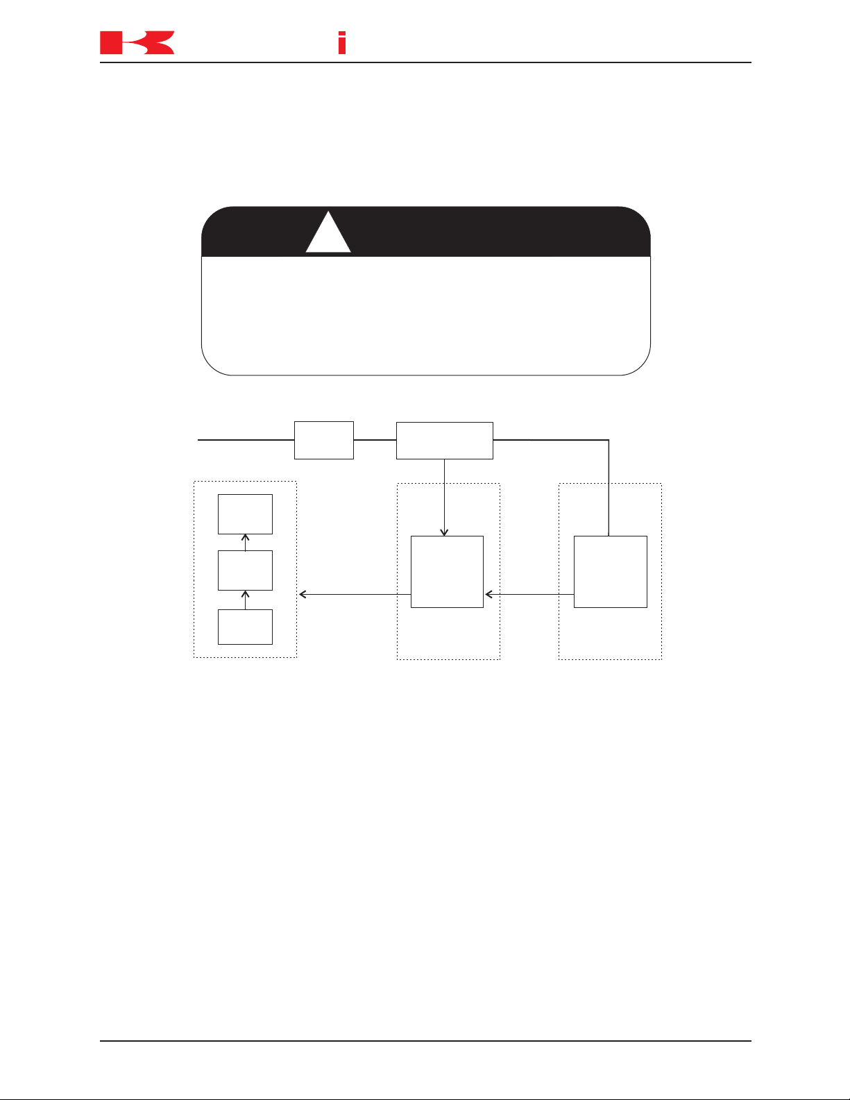
Gate Array
ELPD
Servo
Control
CPU
Interface
CPU
1KX (Mother Board)
1KA (Main CPU Board)
1KB (Servo CPU Board)
Watch Dog
Error Signal
Gate Array
ELPD
Servo
Control
CPU
Interface
CPU
1KX (Mother Board)
1KA (Main CPU Board)
1KB (Servo CPU Board)
TROUBLESHOOTING AND COMPONENT REPLACEMENT
TROUBLESHOOTING
ERROR CODE D1004 [ARM CTRL BOARD] watch dog error of servo control
software.
The watch dog circuit on the 1KA board or 1KB board has detected a software problem.
This is caused by a defective 1KA main CPU board or 1KB servo CPU board or a problem with the servo software.
⇒
Replace the AS or servo software.
⇒
Replace the 1KA or 1KB board.
_____________________________________________________________________
ERROR CODE D1005 Servo board command error. (xx)
Servo software returned an error code, other than a servo system error, to the AS software after receiving an unrecognized command from the 1KA board.
Main causes include:
1. Corrupt servo or AS software.
2. Noise malfunction.
3. Defective 1KB servo board or 1KA main CPU board.
4. Versions of servo and AS software incompatible.
⇒
Install correct versions of servo and AS software.
⇒
Replace the 1KA or 1KB board.
_____________________________________________________________________
1-20 August 9, 2005
Page 24
D SERIES CONTROLLER
K
a
a
aw
s
k
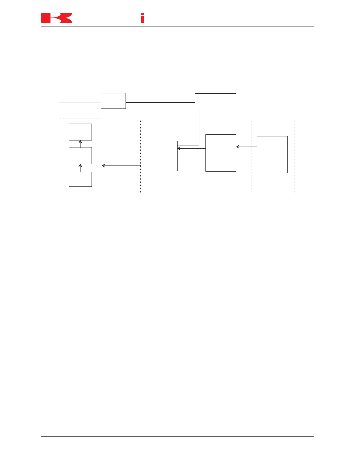
Gate Array
ELPD
Servo
Control
CPU
Interface
CPU
1KX (Mother Board)
1KA (Main CPU Board)
1KB (Servo CPU Board)
1KP (Power Sequence Board)
TROUBLESHOOTING AND COMPONENT REPLACEMENT
TROUBLESHOOTING
ERROR CODE D1006 AMP power unit error.
General servo system error. This error indicates that a servo system error has occurred.
Refer to any other servo system errors which occurred at the same time.
When a servo error signal (SVER) is sent from the 1KB board (servo CPU board) to the
1KP board (power sequence board) motor power is shut down. The error notification is
sent to the AS software via the EPLD. The error information from the 1KB board is sent
through the command line and the corresponding error code(s) is/are displayed after
D1006.
⇒
Check the servo error codes that follow this error for additional information. Ensure
that the 1KP board and 1KB board are properly seated.
_____________________________________________________________________
1-21August 9, 2005
Page 25
D SERIES CONTROLLER
K
a
a
aw
s
k
Regenerative
signal
1KB board
Controller
P-N power
voltage
monitoring
circuit/
Regeneration
controlling
circuit
Drive circuit
1KC: IGBT
1KD: IGBT
1KL/1KR: FET
Regenerative
resistor
Motor power
(P-N power
voltage)
Motor power circuit
Motor power
Power block
Gate Array
Servo
CPU
Interface
CPU
TROUBLESHOOTING AND COMPONENT REPLACEMENT
TROUBLESHOOTING
ERROR CODE D1007 Regenerative time over [XX].
This error occurs when current is sent to regenerative resistors for six or more consecutive seconds.
When the robot decelerates, the motors enter the power generation state to absorb the
inertia energy from the arm. When the P-N power voltage exceeds the rated value (390
VDC), the current is split from the power block to the regenerative resistor. When the
voltage drops to a safe level (365 VDC) the resistor is removed from the circuit.
Main causes include:
1. Abrupt direction changes at high speed.
2. Burned out regenerative resistors in the power block.
3. Defective power block.
4. Defective servo board (1KB board).
5. Loose or disconnected harness between 1KX board (mother board) connector X211
or X212 and the 1KB board (servo CPU board) connector X501 or X502.
6. Defective/incorrect optional second regenerative resistance unit (when used).
⇒
Avoid abrupt high speed direction changes. Change accuracy, speed, add points.
⇒
Replace defective regenerative resistor.
⇒
Install/replace optional second regenerative resistance unit.
⇒
Replace defective 1KB board.
⇒
Replace defective power block.
⇒
Check connections described in item 5 and repair as necessary.
_____________________________________________________________________
1-22 August 9, 2005
Page 26
D SERIES CONTROLLER
K
a
a
aw
s
k
! WARNING
1KB board
1KP board
P-N power low
voltage error
MC unit
(1KQ/1NQ board)
Primary power
Power block
Gate Array
Servo
CPU
Interface
CPU
P-N power
voltage
monitoring
circuit
Main
disconnect
EPLD
K3 STATUS
Motor power
TROUBLESHOOTING AND COMPONENT REPLACEMENT
TROUBLESHOOTING
ERROR CODE D1008 P-N low voltage [XX].
The voltage between P-N supplied to the power block is 60 VDC or less at servo on.
Because motor power is not supplied, when low voltage
occurs, the arm will fall until the error is detected. As a
result, other errors may be generated (abnormal speed,
deviation error, etc.).
Main causes include:
1. Motor power circuit connector detached or loose.
2. Three phase (U, V, W) control power circuit breaker set to OFF.
3. Defective 1KB/1KP/1KQ/1NQ boards.
4. Defective power block.
5. Defective MC unit or harness.
⇒
Ensure the motor power circuit connector is properly attached.
⇒
Ensure control power circuit breaker is set to ON.
⇒
Replace the 1KB/1KP/1KQ /1NQ boards.
⇒
Replace the power block.
⇒
Replace the MC unit or harness.
_____________________________________________________________________
1-23August 9, 2005
Page 27
D SERIES CONTROLLER
K
a
a
aw
s
k
1KB board
Additional regenerative
resistor (option)
P-N power high
voltage error
MC unit
(1KQ/1NQ board)
Primary power
Power block
Gate Array
Servo
CPU
Interface
CPU
P-N power
voltage
monitoring
circuit
Main
disconnect
Motor power
Regenerative
resistor
Thermal
(140° C)
Additional
regenerative
resistor
Thermal
(140° C)
TROUBLESHOOTING AND COMPONENT REPLACEMENT
TROUBLESHOOTING
ERROR CODE D1009 P-N- high voltage [XX].
The voltage between P-N supplied to the power block exceeded 410 VDC.
Main causes include:
1. High inertia loads due to excessive tool weight or incorrect program data.
2. Defective regenerative resistance control circuit, overheat failure of regenerative
resistance unit, defective voltage monitoring circuit, or defective power block.
3. Defective servo board (1KB board) or harness.
4. Defective additional regenerative resistance unit.
⇒
Reteach program steps to eliminate sudden high speed direction changes (dynamic
shock).
⇒
Replace the regenerative unit.
⇒
Replace the 1KB board, power block or harness.
⇒
Replace the additional regenerative resistor unit.
_____________________________________________________________________
1-24 August 9, 2005
Page 28
D SERIES CONTROLLER
K
a
a
aw
s
k
1KB board
Additional regenerative
resistor (option)
P-N power high
voltage error
MC unit
(1KQ/1NQ board)
Primary power
Power block
Gate Array
Servo
CPU
Interface
CPU
P-N power
voltage
monitoring
circuit
Main
disconnect
Motor power
Regenerative
resistor
Thermal
(140° C)
Additional
regenerative
resistor
Thermal
(140° C)
TROUBLESHOOTING AND COMPONENT REPLACEMENT
TROUBLESHOOTING
ERROR CODE D1010 Regenerative resistor over-heat [XX].
The thermal switch for the power block regenerative resistor unit, or the optional regenerative resistor unit reached 140° C (284°F), or the heat sink thermal switch reached
90° C (194°F), or the controller cabinet thermal switch reached 70° C (158° F). The
thermal switches are wired in series and the AS software cannot distinguish which
thermal switch is activated. For D7X controller, if the heat exchange fan is inoperative
(X207 disconnected) this error is generated.
Main causes include:
1. High inertia loads due to excessive tool weight or incorrect program data.
2. Defective cooling fans.
3. Insufficient clearance for air circulation.
4. High ambient controller temperature.
5. Defective power block.
6. Disconnected or defective harness between the 1KC/1KD board and the additional
regenerative resistor unit.
7. Defective regenerative resistor unit.
8. Defective additional regenerative resistor unit.
9. Defective 1KB board.
10. Disconnected or defective harness between X211 or X212 on the 1KX/1NX board
and X501 or X502 on the power block.
1-25August 9, 2005
Page 29

D SERIES CONTROLLER
K
a
a
aw
s
k
TROUBLESHOOTING AND COMPONENT REPLACEMENT
TROUBLESHOOTING
⇒
Reteach program steps to eliminate sudden high speed direction changes (dynamic
shock).
⇒
Ensure cooling fans are in proper working condition.
⇒
Reduce controller ambient temperature.
⇒
Replace defective thermal switch(es).
⇒
Repair or replace disconnected or defective harness(es).
⇒
Replace the regenerative unit.
⇒
Replace the 1KB board, power block or harness.
⇒
Replace the additional regenerative resistor unit.
⇒
Connect or repair D7X power supply connection for heat exchange fan (X207).
_____________________________________________________________________
ERROR CODE D1011 AS or servo software is not compatible with the robot
model.
This error occurs when the servo software does not match the robot specifications.
⇒
Load the correct AS and servo software.
_____________________________________________________________________
ERROR CODE D1012 Servo type mismatch. Check the settings.
Servo type set for the robot and servo software do not match.
⇒
Change the robot servo type setting
⇒
Install servo software that matches the robot setting.
_____________________________________________________________________
.
1-26 August 9, 2005
Page 30
D SERIES CONTROLLER
K
a
a
aw
s
k
1KB board
1KP board
P-N capacitor
discharge error
MC unit
(1KQ/1NQ board)
Primary power
Power block
Gate Array
Servo
CPU
Interface
CPU
P-N power
voltage
monitoring
circuit
Main
disconnect
EPLD
K3 STATUS
Motor power
TROUBLESHOOTING AND COMPONENT REPLACEMENT
TROUBLESHOOTING
ERROR CODE D1013 P-N capacitor is not discharged.
This error occurs when motor power is OFF for a period of time and the P-N power
voltage does not decrease to 60 VDC or less.
Main causes include:
1. Defective 1KB/1KP/1KQ/1NQ boards.
2. Defective power block.
3. Defective MC unit or harness between the MC unit and the power block.
⇒
Replace the 1KB/1KP/1KQ/1NQ boards
⇒
Replace the power block.
⇒
Replace the MC unit or harness between the MC unit and the power block.
.
_____________________________________________________________________
ERROR CODE D1014 Servo system error. (Code=XX)
An unrecognized error occurred in the 1KB board.
⇒
Contact KRI customer service (include operating conditions/settings at the time the
error occurred)
_____________________________________________________________________
ERROR CODE D1015 The servo data file does not exist.
.
This error occurs when the servo data file is not found.
⇒
Contact KRI customer service (include operating conditions/settings at the time the
error occurred)
.
_____________________________________________________________________
1-27August 9, 2005
Page 31

D SERIES CONTROLLER
K
a
a
aw
s
k
TROUBLESHOOTING AND COMPONENT REPLACEMENT
TROUBLESHOOTING
ERROR CODE D1016 Data applicable to the robot model not in servo servo data
file.
This error occurs when the installed robot model file is not found in the servo data file.
⇒
Contact KRI customer service (include operating conditions/settings at the time the
error occurred)
_____________________________________________________________________
ERROR CODE D1017 Error of download of servo data.
Servo data could not be downloaded from the servo software at controller power-up.
⇒
Ensure the correct servo software is installed.
⇒
Ensure the 1KA and 1KB boards are properly installed
_____________________________________________________________________
.
.
1-28 August 9, 2005
Page 32

D SERIES CONTROLLER
K
a
a
aw
s
k
Encoder I/F
1KB board
Encoder power supply +12 V
Controller
Robot
Power circuit
Battery
Encoder
Encoder
1FG/1HG board
TROUBLESHOOTING AND COMPONENT REPLACEMENT
TROUBLESHOOTING
ERROR CODE D1500 Encoder misread error JtXX.
Immediately after control power on, steady encoder data is not able to be read. This
error is caused by a disconnected encoder signal line or a short circuit, or a defect in the
main body of the encoder.
Main causes include:
1. Defective encoder or encoder harness.
2. Defective servo weld gun encoder (detected at controller power-up/power-down with
gun connected.
3. Servo weld gun is not connected.
4. Defective 1KB board.
5. Defective 1FG/1HG board.
⇒
Check for disconnection or short circuit in encoder signal line.
⇒
Replace the encoder or encoder harness.
⇒
Replace the 1KB servo board.
⇒
Replace the 1FG/1HG board.
⇒
Release the servo weld gun axis in teach mode and cycle controller power OFF and
ON.
_____________________________________________________________________
1-29August 9, 2005
Page 33

D SERIES CONTROLLER
K
a
a
aw
s
k
Robot
Motors
Current
sensor
1GM board
I/V
converter
HIC
(Over current
detection)
Gate
Array
IPM
Controller
Power block
PWM
Over current
error signal
Current
feedback
1KB Board
U, V, W
earth
TROUBLESHOOTING AND COMPONENT REPLACEMENT
TROUBLESHOOTING
ERROR CODE D1501 Defective gun changer connection or encoder comm. error.
This error occurs when the servo weld gun is connected and encoder data is not read
normally within the specified time.
Main causes include:
1. Improper connection at the tool changer.
2. Defective encoder or encoder communication line.
⇒
Check tool changer connection and repair as necessary
⇒
Check encoder and encoder harness and replace as necessary.
.
_____________________________________________________________________
ERROR CODE D1502 Amp over current JtXX.
The feedback current from a current sensor in the power block exceeded 150% of the
maximum instantaneous motor current rating.
Main causes include:
1. Short in the U, V, W from the power block to motor and ground wire.
2. Defective motor.
3. Defective power block.
4. Defective 1KB servo board, harness, etc.
⇒
⇒
Check the connection for the U, V, W and ground line to the power block. Replace the
separation harness if necessary.
Replace the motor, 1KB board, power block, or harness.
_____________________________________________________________________
1-30 August 9, 2005
Page 34

D SERIES CONTROLLER
K
a
a
aw
s
k
HCnoitacinummoCoT
ecneuqeSrewoPotyaleR
)draoBCPPK1(draoB
AtinUAdraoBCPBK1tsriFretsaM
BtinUBdraoBCPBK1tsriFrets
aM
CtinUCdraoBCPBK1tsriFevalS
ro
tinUAdraoBCPBK1dnoceS
ro
reifilpmAsixAenO
D
tinUBdraoBCPBK1dnoceS
evalS
ro
reifi
lpmAsixAenO
TROUBLESHOOTING AND COMPONENT REPLACEMENT
TROUBLESHOOTING
ERROR CODE D1503 Current detector type (XX) mismatch!
When the control power supply is turned ON, the ID code data of the 1GM (1KV) board
and the AS software installed on the 1KB board do not correspond. The unit name of
the servo board displayed at (XX) in the error message corresponds to the CH column
in the table below.
Main causes include:
1. 1GM (1KV) board is not suitable for the AS software (robot model).
2. The AS software does not correspond to the 1GM (1KV) board.
⇒
Ensure the correct AS software is loaded.
⇒
Replace the 1GM (1KV) board.
_____________________________________________________________________
1-31August 9, 2005
Page 35

D SERIES CONTROLLER
K
a
a
aw
s
k
Robot
Motors
Current
sensor
1GM board
I/V
converter
Servo CPU
IPM
Controller
Power block
Current
feedback
1KB Board
U, V, W
earth
TROUBLESHOOTING AND COMPONENT REPLACEMENT
TROUBLESHOOTING
ERROR CODE D1504 Abn. curr. feedback Jt XX. (Amp fail, pwr harness discon-
nect).
This error occurs if the current feedback value is near 0 from the time the servo is turned
ON until the brake is released, even if the commanded current value meets or exceeds
the expected current.
Main causes:
1. Motor power line U, V, and/or W phase are disconnected.
2. Improper power harness line connection.
3. Defective power block
⇒
Check the power line wiring and repair or replace as necessary.
⇒
Replace the power block.
_____________________________________________________________________
1-32 August 9, 2005
Page 36

D SERIES CONTROLLER
K
a
a
aw
s
k
1KB board
Gate Array
Servo
CPU
Interface
CPU
1KQ/1NR board
Controller
Photo coupler
Upper arm
Rotor trunk
Thermal switch
Thermal switch
Thermal line
(TH)
Robot
TROUBLESHOOTING AND COMPONENT REPLACEMENT
TROUBLESHOOTING
ERROR CODE D1505 Motor harness disconnected or over heat. (XX)
Motor thermal circuit is open due to motor overheat or harness problem. Not all robot
models utilize thermal switches in the motors. Some robot models may have multiple
thermal switches connected in series (see diagram below). The FS03/06/10/20 robot
models have the thermal switch mounted near JT1 motor. The FS03 model is calibrated
to 55° C and FS06/10/20 models are calibrated to 65° C
Main causes include:
1. Disconnected thermal line.
2. Defective connection in the separation harness.
3. Defective 1KB servo board.
4. Defective 1KQ/1NR board.
5. When the motor thermal switch is used:
– The robot rated weight capacity is exceeded.
– The ambient temperature exceeds limits for use.
– Excessive execution of abrupt high speed direction changes.
– Defective controller cooling fan or cooling air purge system.
– Servo system holding the robot arm in high load position for extended periods.
– Defective thermal switch.
⇒
When the thermal switch opens, error cannot be reset until cooling is complete.
⇒
Confirm continuity of thermal line.
⇒
Replace the harness or the 1KB servo board as necessary.
⇒
⇒
Replace the 1KQ/1NR board.
Use the auto servo off function, AUX 0808, to prevent the servo system holding a
high load arm position for extended periods.
_____________________________________________________________________
1-33August 9, 2005
Page 37

D SERIES CONTROLLER
K
a
a
aw
s
k
1KB board
IPM error signal
Power block
Gate Array
Servo
CPU
Interface
CPU
PWM signal
Controller
HIC
IPM
Motor
Robot
TROUBLESHOOTING AND COMPONENT REPLACEMENT
TROUBLESHOOTING
ERROR CODE D1506 Power module error JtXX.
An error signal from the IPM module in the power block is detected by the 1KB board.
Main causes include:
1. U, V, and W phase short-circuited or short-circuited to ground wire.
2. Payload weight exceeds rating.
3. Defective cooling fan in the power block.
4. Ambient temperature above normal operating limits.
5. Constant execution of abrupt high speed direction changes.
6. Defective 1KB board.
7. Disconnected or defective harness between the 1KB board and the power block.
8. Disconnection or poor connection in the thermal line at the separate harness and/or
controller harness.
9. Defective thermal switch in the controller or servo motors (if used).
10. Defective power block.
⇒
Check and repair cause of U, V, and W phase short-circuited or short-circuited to
ground wire.
⇒
Ensure payload does not exceed rating.
⇒
Reduce ambient temperature.
⇒
Ensure cooling fans are in proper working condition.
⇒
Correct abrupt high speed direction changes in the robot program.
⇒
Replace the 1KB board.
⇒
Repair or replace the harness between the 1KB board and the power block.
⇒
Check the thermal line in the separate harness and controller harness, and repair or
replace as necessary.
⇒
Replace the power block.
_____________________________________________________________________
1-34 August 9, 2005
Page 38

D SERIES CONTROLLER
K
a
a
aw
s
k
Mother Board
1KP board
1KB board
1KX board
EPLD
AVR
output
cut
AVR for
control power
Main
disconnect
Primary
power
Control
power
210 VAC
AC error
signal
REMOTE
Local
bus
F1
T1 F3
1KQ/1NQ board
Transformer
Circuit
breaker
TROUBLESHOOTING AND COMPONENT REPLACEMENT
TROUBLESHOOTING
ERROR CODE D1507 AC primary power OFF.
This error occurs when there is an instantaneous decrease in the primary power to the
AVR for control power supply (130–145 VAC or less for 20–30 msec).
Main causes include:
1. The primary power is below the specified rating, or an instantaneous power decrease
occurred.
2. The non-fuseable breaker (NFB) F1 for the control power supply is turned OFF or
tripped due to a short-circuit.
3. An instantaneous decrease in the 210 VAC supply to AVR for the control power
supply.
4. Circuit breaker F3 is OFF or tripped due to a short circuit.
5. Defective AVR.
6. Defect in the primary power supply.
7. Defective 1KP board.
8. Defective 1KQ/1NQ board.
⇒
It is normal for this error to occur when NFB F1 is set OFF and back ON.
⇒
Check power supply circuit through NFB F1 and repair as necessary.
⇒
Check power supply circuit to the AVR through the circuit breaker F3 and repair as
necessary.
⇒
Confirm that primary power is supplied according to specifications.
⇒
Replace the 1KP board.
⇒
Replace the 1KQ/1NQ board.
⇒
Replace the AVR.
_____________________________________________________________________
1-35August 9, 2005
Page 39

D SERIES CONTROLLER
K
a
a
aw
s
k
Mother Board
1KP board
1KB board
1KX board
EPLD
24 VDC
monitor
AVR for
control power
Main
disconnect
Primary
power
Control
power
210 VAC
DC error
signal
Local
bus
F1
T1
F3
1KQ/1NQ board
Transformer
Circuit
breaker
TROUBLESHOOTING AND COMPONENT REPLACEMENT
TROUBLESHOOTING
ERROR CODE D1508 24VDC power source is too low.
24 VDC to the power sequence board has dropped to +21.6 VDC or less.
Main causes include:
1. Defective AVR for control power supply.
2. Defective 1KP board.
3. Defective 1KQ/1NQ board.
4. Short circuit in the motor power on circuitry, the EMERGENCY STOP switch, or axis
restriction limit switch circuits.
5. Short in machine valve and sensor circuits.
⇒
Check the power supply, machine valve, and the sensor circuits for short circuits.
⇒
Ensure the 24 VDC load does not exceed the power supply capacity.
⇒
Check the AVR, the 1KP power sequence board, and the 1KQ/1NQ relay board and
replace as necessary.
_____________________________________________________________________
1-36 August 9, 2005
Page 40

D SERIES CONTROLLER
K
a
a
aw
s
k
Mother Board
1KP board
1KX board
EPLD
AVR
output
cut
AVR for
control power
Main
disconnect
Primary
power
Control
power
210 VAC
AC error
signal
Local
bus
F1
T1 F3
1KQ/1NQ board
Transformer
Circuit
breaker
REMOTE
TROUBLESHOOTING AND COMPONENT REPLACEMENT
TROUBLESHOOTING
ERROR CODE D1509 Primary power source is too high.
Voltage level of the AVR for the control power supply is too high (267-277 VAC or more
for 1-2 sec.).
Main causes include:
1. Primary power exceeds the specified rating.
2. Defective AVR.
3. Defective 1KP power sequence board.
4. Defective 1KQ/1NQ relay board.
5. Power supply circuit problem.
⇒
Ensure the power supply to the controller is within ratings.
⇒
Check power supply circuit to the AVR.
⇒
Confirm the supply power is within specifications.
⇒
Replace the 1KP board.
⇒
Replace the 1KQ/1NQ board.
⇒
Replace the AVR.
_____________________________________________________________________
1-37August 9, 2005
Page 41

D SERIES CONTROLLER
K
a
a
aw
s
k
Mother Board
1KP board
1KB board
1KX board
EPLD
AVR for
control power
Main
disconnect
Primary
power
Control
power
210 VAC
AC error
signal
Local
bus
F1
T1 F3
1KQ/1NQ board
Transformer
Circuit
breaker
TROUBLESHOOTING AND COMPONENT REPLACEMENT
TROUBLESHOOTING
ERROR CODE D1510 Primary power source is too low.
Voltage level of the AVR primary power supply is too low (150-158 VAC or less for 1-2
sec.).
Main causes include:
1. Drop in the primary power supply voltage.
2. Defective AVR.
3. Defective NFB F1.
4. Defective 1KP power sequence board.
5. Defective 1KQ/1NQ relay board.
6. Power supply circuit problem.
⇒
Verify the power supply to the controller is within ratings.
⇒
Check the AVR and NFB F1 and replace as necessary.
⇒
Confirm supply power is within specifications.
⇒
⇒
Replace the 1KP board.
Replace the 1KQ/1NQ board.
_____________________________________________________________________
1-38 August 9, 2005
Page 42

TROUBLESHOOTING AND COMPONENT REPLACEMENT
K
a
a
aw
s
k
TROUBLESHOOTING
ERROR CODE D1511 +12VDC or -12VDC is abnormal.
+/-12 VDC supplied to the 1KA board is out of specifications.
+12 VDC: +10.75 VDC or less.
-12 VDC: -10.4 VDC or more.
Main causes include:
1. Defective AVR.
2. Defective 1KA, 1KB, or 1KP board.
3. Power supply contacts in the motherboard are damaged.
5. Defective power block.
6. Defective 1FG/1HG board.
7. Short in the harness between the servo unit and the 1FG board.
8. Short in the optional circuit boards, i.e., vision, etc.
9. Insufficient DC power supply capacity to support optional boards.
D SERIES CONTROLLER
⇒
Adjust the AVR output voltage.
⇒
Replace the AVR and each board for the control power supply.
⇒
Check for short circuits in the operation panel and separation harness and replace as
necessary.
_____________________________________________________________________
1-39August 9, 2005
Page 43

D SERIES CONTROLLER
K
a
a
aw
s
k
Transformer Circuit breaker
MOSFET
Voltage
monitoring
1KP board
Motor
1KB board
Robot
Controller
Safety circuit
Brake power supply error signal
Brake release signal
Brake line error signal
1KQ/1NR board
+24 VDC
Brake power supply D3X
Brake power supply D7X
Motor brake line
Motor power
Servo control
Brake release
ON
START
RELEASE
Disconnection
detected
Short-circuit
detected
TROUBLESHOOTING AND COMPONENT REPLACEMENT
TROUBLESHOOTING
ERROR CODE D1512 Brake line error for JtXX.
This error occurs when the 1KB board detects an error signal sent from the brake release control MOSFET on the 1KQ/1NR board.
Brake line errors are not detected during motor power OFF. Brake line disconnection is
not detected during automatic operation. Brake line error detection timing is shown in
the diagram below.
Main causes include:
1. Disconnection/short-circuit/ground fault/poor connection at the brake line axis motor
harness.
2. Defective connection for the brake power line.
3. Defective connection or harness between the 1KB and 1KQ/1NR boards.
4. Defective connection or harness between the 1KB and 1KX/1NX boards.
5. Defective connection or harness between the 1NR and 1NX boards.
6. Incorrect 1KP board safety circuit setting.
7. Defective 1KB or 1KQ/1NR board.
⇒
Check for disconnection or short-circuit in the motor harness, and repair or replace as
1-40 August 9, 2005
Page 44

D SERIES CONTROLLER
K
a
a
aw
s
k
Transformer Circuit breaker
MOSFET
Voltage
monitoring
1KP board
Motor
1KB board
Robot
Controller
Safety circuit
Brake power supply error signal
Brake release signal
Brake line error signal
1KQ/1NR board
+24 VDC
Brake power supply D3X
Brake power supply D7X
Motor brake line
TROUBLESHOOTING AND COMPONENT REPLACEMENT
TROUBLESHOOTING
necessary.
⇒
Check and repair brake power line and connections as necessary
⇒
Check and repair connections between 1KB and 1KQ/1NR, 1KB and 1KX/1NX, and
.
1NR and 1NX as necessary.
⇒
Ensure the 1KB board is properly seated in the card rack.
⇒
Ensure the 1KP board safety circuit setting is correct.
⇒
Replace the 1KB and or the 1KQ/1NR.
_____________________________________________________________________
ERROR CODE D1513 Brake power is abnormal. (XX)
This error occurs when the 1KB board detects an error signal sent from the brake power
supply, voltage monitoring circuit, on the 1KQ/1NR board.
Main causes include:
1. Defective transformer winding for brake power supply.
2. Short or open in wiring from transformer to brake power supply circuit.
3. Disconnected or defective harness between the 1KB board and the 1KQ/1NR board.
4. 1KB board not properly seated in the 1KX/1NX board.
5. 1NR board not properly seated in the 1NX board.
6. Defective circuit breaker F4 or F4 tripped.
7. Defective MC unit (1KQ board).
8. Defective 1NR board.
⇒
Check transformer winding and wiring and repair or replace as necessary
⇒
Repair or replace harness between the 1KB and 1KQ/1NR board.
⇒
Ensure the 1NR and or the 1KB boards are properly seated in the 1KX/1NX board.
⇒
Replace MC unit.
⇒
Reset or replace circuit protector F4 as necessary.
⇒
Replace the 1KB and or 1KQ/1NR boards as necessary.
_____________________________________________________________________
.
1-41August 9, 2005
Page 45

D SERIES CONTROLLER
K
a
a
aw
s
k
TROUBLESHOOTING AND COMPONENT REPLACEMENT
TROUBLESHOOTING
ERROR CODE D1514 I/O 24V fuse is open.
Fuse F2 on the 1KP board is open.
Main causes include:
1. Solenoid valve or diode polarity reversed.
2. Current load on the 24 VDC I/O circuit exceeds rating.
3. Short-circuit or ground fault in the 24 VDC I/O harness.
4. Defective 1KP board.
⇒
Check components for proper polarity and repair as necessary
Ensure the load on the 24 VDC I/O circuit is within rating.
⇒
⇒
Check the I/O harness and replace as necessary.
⇒
Replace fuse F2 on the 1KP board (after cheching for short-circuit).
⇒
If the above steps do not correct the problem, replace the 1KP board.
_____________________________________________________________________
.
ERROR CODE D1515 Mismatch in setting of safety circuit as single/double.
Main causes include:
1. Safety circuit setting between the software and hardware do not match.
2. Defective 1KP board.
⇒
Set SW-2 on the 1KP board to ON for a double circuit or OFF for a single circuit
In AUX 2021-2 set [2 Line] ON or [1 Line] OFF.
⇒
⇒
Replace 1KP board.
_____________________________________________________________________
ERROR CODE D1516 Mismatch betw hard/software settings for HOLD backup
time.
Main causes include:
1. The setting that specifies a two second delay before motor power is set OFF when
the RUN/HOLD switch is switched from RUN to HOLD, is not matched between the
software and hardware.
2. Defective 1KP board.
⇒
Set SW-1 on the 1KP board to ON for two second delay or OFF no delay
⇒
In AUX 2021-2 set the delay parameter to [standard] (delay) or [Off] (no delay).
⇒
Replace 1KP board.
_____________________________________________________________________
.
.
1-42 August 9, 2005
Page 46

D SERIES CONTROLLER
K
a
a
aw
s
k
TROUBLESHOOTING AND COMPONENT REPLACEMENT
TROUBLESHOOTING
ERROR CODE D1517 Blown fuse on safety circuit emergency line.
Fuse F1 on the 1KP board is open.
Main causes include:
1. Incorrect wiring in the emergency line (wiring harness, emergency stop, safety fence,
external trigger, teach pendant, limit switches).
2. Short-circuit in the emergency line (wiring harness, emergency stop, safety fence,
external trigger, teach pendant, limit switches).
3. Defective 1KP board.
⇒
Check wiring and components in the safety circuit emergency line and repair/replace
as necessary
⇒
Replace 1KP board.
⇒
Ensure the controller power is set OFF, when wiring safety circuits. The fuse F1 will
blow if wiring is shorted.
_____________________________________________________________________
.
ERROR CODE D1518 Mismatch in the Emer. Stop condition safety circuit.
Main causes include:
1. When the system is set for double safety circuits, and the circuits at the operation
panel, teach pendant, and/or the external emergency stop switch are wired as single
circuits.
2. Disconnection or ground fault in the emergency stop circuit.
3. Defective 1KP board.
⇒
With the E-STOP switch(es) engaged, check wiring harness and switches in the
circuit and repair or replace as necessary
⇒
Ensure all contacts in the external emergency stop circuit are wired correctly (double
circuits).
⇒
If the above steps do not correct the problem, replace the 1KP board.
_____________________________________________________________________
.
1-43August 9, 2005
Page 47

D SERIES CONTROLLER
K
a
a
aw
s
k
TROUBLESHOOTING AND COMPONENT REPLACEMENT
TROUBLESHOOTING
ERROR CODE D1519 Mismatch of the safety circuit LS condition.
In a double safety circuit system, conditions set for contacts in the limit switch (LS)
circuit do not match.
Main causes include:
1. Defective harness connection or harness (short-circuit or ground fault in harness).
2. Defective LS override switch.
3. Defective 1KP board
⇒
Replace the controller/separate/machine harness(es).
⇒
Replace the LS override switch.
⇒
Replace the 1KP board.
_____________________________________________________________________
ERROR CODE D1520 Mismatch of the safety circuit TEACH/REPEAT condition.
Main causes include:
1. TEACH/REPEAT switch setting and relay conditions for switching teach/repeat modes
do not match.
2. Contact condition at the TEACH/REPEAT switch does not match between the first
and second safety circuits.
3. Defective 1KP board.
⇒
Check the TEACH/REPEAT switch and relays (RY5 and RY6 on the 1KP board), and
replace as necessary.
⇒
Replace the 1KP board.
_____________________________________________________________________
ERROR CODE D1521 Mismatch in safety circuit safety-fence condition.
In a double safety circuit system, conditions set for contact at the safety fence circuit do
not match.
Main causes include:
1. Incorrect circuit or wiring for safety fence circuit (single circuit wired).
2. Disconnection or ground fault in the safety fence circuit wiring.
3. Defective safety fence switch.
4. Defective 1KP board.
⇒
Inspect contact points at the safety fence circuit and repair or replace as necessary
⇒
Replace the 1KP board.
_____________________________________________________________________
1-44 August 9, 2005
.
Page 48

D SERIES CONTROLLER
K
a
a
aw
s
k
NOTE
TROUBLESHOOTING AND COMPONENT REPLACEMENT
TROUBLESHOOTING
ERROR CODE D1522 Mismatch in cond. of safety circuit enabling device.
In a double safety circuit system, conditions set for contacts at the TRIGGER switch
circuit do not match.
If the trigger switch is not pressed firmly, only one contact may engage resulting in this error. The trigger
switch has three positions and pressing too firmly may
disengage the trigger circuit.
Replace the teach pendant, teach pendant harness or controller harness to the teach
⇒
pendant connector.
⇒
Replace the 1KP board.
_____________________________________________________________________
ERROR CODE D1523 Mismatch in cond. of safety circuit enabling device.
In a double safety circuit system, conditions set for contacts at the EXTERNAL TRIGGER switch circuit do not match.
⇒
Inspect contacts on the EXT.TRIGGER switch and replace as necessary
⇒
Check for disconnection or short-circuit in external trigger wiring and repair as necessary.
⇒
Replace the 1KP board.
_____________________________________________________________________
ERROR CODE D1524 Incorrect operation of the safety relay.
Safety relay on the 1KQ board did not operate correctly.
Main causes include:
1. Defective controller harness.
2. Defective 1KQ board
3. Defective MC unit.
4. Defective 1KP board.
.
⇒
Replace controller harness.
⇒
Replace the 1KQ board
⇒
Replace the MC unit.
⇒
Replace the 1KP board.
_____________________________________________________________________
.
1-45August 9, 2005
Page 49

D SERIES CONTROLLER
K
a
a
aw
s
k
TROUBLESHOOTING AND COMPONENT REPLACEMENT
TROUBLESHOOTING
ERROR CODE D1525 Incorrect operation of MC (K1).
Main causes include:
1. Defective controller harness.
2. Defective magnetic contactor K1.
3. Defective MC unit (1KQ/1NQ board).
4. Defective 1KP board.
⇒
Replace controller harness
Replace magnetic contactor K1.
⇒
⇒
Replace MC unit
⇒
Replace 1KP board.
_____________________________________________________________________
ERROR CODE D1526 Incorrect operation of MC (K2).
(1KQ/1NQ board)
.
.
Main causes include:
1. Defective controller harness.
2. Defective magnetic contactor K2.
3. Defective MC unit (1KQ/1NQ board).
4. Defective 1KP board.
⇒
Replace controller harness
⇒
Replace magnetic contactor K2.
⇒
Replace MC unit
⇒
Replace 1KP board.
_____________________________________________________________________
ERROR CODE D1527 Incorrect operation of MC (K3).
Main causes include:
1. Defective controller harness.
2. Defective magnetic contactor K3.
3. Defective MC unit (1KQ/1NQ board).
4. Defective 1KP board.
⇒
Replace controller harness
Replace magnetic contactor K3.
⇒
⇒
Replace MC unit
⇒
Replace 1KP board.
_____________________________________________________________________
(1KQ/1NQ board)
(1KQ/1NQ board)
.
.
.
.
1-46 August 9, 2005
Page 50

D SERIES CONTROLLER
K
a
a
aw
s
k
TROUBLESHOOTING AND COMPONENT REPLACEMENT
TROUBLESHOOTING
ERROR CODE D1528 Controller temperature is out of range.
Temperature inside the controller exceeds specification.
Main causes include:
1. Defective cooling fan(s). For D7X controller, defective heat exchange fan on the left
side of the controller.
2. Ambient temperature above specified rating.
3. Defective 1KP board.
⇒
Inspect cooling fans for proper operation and replace fans and/or fan harness(es) as
necessary
⇒
Ensure air inlet filter is not restricted.
⇒
Lower ambient temperature within specifications.
⇒
Replace the 1KP board.
_____________________________________________________________________
.
ERROR CODE D1529 Signal harness is disconnected or encoder power error.
This error is caused when a communication error occurs for all axes.
Main causes include:
1. Separate harness disconnected or poor connection.
2. Abnormality in encoder power supply.
3. Low battery voltage on the encoder battery board (1FG/1HG).
4. Defective encoder battery board (1FG/1HG).
⇒
Ensure proper connections at the separate harness
⇒
Ensure proper encoder power is supplied.
⇒
Replace batteries on the encoder battery board (1FG/1HG).
⇒
Replace the encoder battery board (1FG/1HG).
_____________________________________________________________________
ERROR CODE D1530 Abnormal current limit of JtXX.
Main causes include:
1. Ground fault in the motor power line U/V/W.
2. Unavailable program data.
.
⇒
Check motor power line and replace as necessary.
⇒
Modify program data.
_____________________________________________________________________
1-47August 9, 2005
Page 51

D SERIES CONTROLLER
K
a
a
aw
s
k
TROUBLESHOOTING AND COMPONENT REPLACEMENT
TROUBLESHOOTING
ERROR CODE D1531 Heat sink on power block overheated.
Main causes include:
1. Temperature inside the controller above specification because of air inlet or outlet
blockage.
2. Defective cooling fan.
3. Defective power block.
⇒
Ensure air inlet and outlet ports are clear.
⇒
Ensure cooling fans are in proper working order.
⇒
Replace the power block.
_____________________________________________________________________
ERROR CODE D2000 No response from Comm. board for laser sensor.
Laser sensor communication board program stopped.
⇒
Set robot controller and laser sensor power OFF. Set laser sensor power ON then set
robot controller power ON
_____________________________________________________________________
ERROR CODE D2001 RI/O or C-NET board initialize error.
Initial data processing between the 1KA and 1FS/1HS boards is not correctly completed
at controller power-up.
Main causes include:
1. Defective 1KA board.
2. Defective 1FS/1HS board.
3. Noise related malfunction.
⇒
Ensure the 1KA and 1FS/1HS boards are properly seated into the 1KX/1NX board.
⇒
Ensure harnesses are properly connected at the 1KA and 1FS/1HS boards.
⇒
Check for noise malfunction and shield integrity.
⇒
Replace the 1KA board.
⇒
Replace the 1FS/1HS board.
_____________________________________________________________________
.
1-48 August 9, 2005
Page 52

D SERIES CONTROLLER
K
a
a
aw
s
k
TROUBLESHOOTING AND COMPONENT REPLACEMENT
TROUBLESHOOTING
ERROR CODE D2002 No response from the arm ID board.
Main causes include.
1. Defective 1KB board.
2. Defective 1KP board.
3. Defective 1GV arm ID board.
4. Defective harness.
5. Noise related malfunction.
⇒
Replace 1KB board.
⇒
Replace 1KP board.
⇒
Replace 1GV board.
⇒
Replace harness.
⇒
Check for noise malfunction and shield integrity.
_____________________________________________________________________
ERROR CODE D2003 No data in the arm ID board.
This error occurs when data is not present in the arm ID board (1GV) memory. This
error cannot be reset.
⇒
Execute the ZROBOT.ZZERO instruction and transfer the data to the arm ID board
(1GV).
⇒
Replace the arm ID board (1GV).
_____________________________________________________________________
ERROR CODE D2004 Mismatch data in the arm ID board.
This error occurs when robot data, other than the serial number, is different between the
arm ID board (1GV) and in the processor board (1KA). This error cannot be reset.
⇒
Robot data in the controller 1KA board and robot data in the arm ID 1GV board do
not match, confirm correct data is used.
⇒
Execute the ZBLTARM_ALLSET instruction and transfer the data from the controller
1KA board to the arm ID 1GV board.
_____________________________________________________________________
ERROR CODE D2005 CC-LINK software version mismatch.
Software versions installed in the 1HS board and AS software are incompatible.
⇒
Check 1HS board and AS software versions and reload software as necessary.
_____________________________________________________________________
1-49August 9, 2005
Page 53

D SERIES CONTROLLER
K
a
a
aw
s
k
TROUBLESHOOTING AND COMPONENT REPLACEMENT
TROUBLESHOOTING
ERROR CODE D2006 Communication board to explosion-proof teach pendant
watch-dog error.
This error occurs when the CPU on the communication board (1GS board) for the explosion-proof teach pendant is suspended.
Main causes include:
1. Defective communication board (1GS board).
2. Defective main CPU board (1KA board).
⇒
Replace defective 1GS board.
⇒
Replace defective 1KA board.
_____________________________________________________________________
ERROR CODE D2007 No response from the built-in sequence board.
This error occurs when the built-in PLC is in an error condition or the program mode.
⇒
Cycle the controller power OFF and ON after the cause of the built-in PLC error is
corrected.
⇒
Set the built-in PLC to the operating mode.
_____________________________________________________________________
ERROR CODE D2008 Arm ID I/F board error. (code XX).
This error occurs when a communication error exists between the arm ID board interface board (1KP) and the arm ID board (1GV) (abnormal ROM, RAM, DPRAM, etc.).
⇒
Replace the arm ID board (1GV).
⇒
Replace the arm ID interface board (1KP).
⇒
Check and repair or replace harnesses and connections as necessary.
_____________________________________________________________________
ERROR CODE D2010 Sync. error between user I/F and arm control board.
1KA and 1KB board synchronization failed for 1 second or more.
⇒
Replace 1KA board
Replace 1KB board
⇒
_____________________________________________________________________
1-50 August 9, 2005
.
.
Page 54

D SERIES CONTROLLER
K
a
a
aw
s
k
TROUBLESHOOTING AND COMPONENT REPLACEMENT
TROUBLESHOOTING
ERROR CODE D2011 Parameter download error between user I/F & arm ctrl
boards.
1KA and 1KB boards parameter exchange cannot be downloaded.
⇒
Replace the 1KA board.
⇒
Replace the 1KB board.
_____________________________________________________________________
ERROR CODE D2012 SOFT ABSORBER error. Turn OFF & ON the control
power.
(Software absorber function)
Main causes include:
1. Abnormality during soft absorber sequence.
2. 1KB board upload/download is requested, but not executed.
⇒
Cycle controller power OFF and ON.
⇒
Replace the 1KB board.
⇒
If the error recurs, contact KRI Customer Service
_____________________________________________________________________
ERROR CODE D2013 CHANGE GAIN Error. Turn OFF & ON the control power.
(Change gain function)
Main causes include:
1. Abnormality during change gain sequence.
2. 1KB board upload/download is requested, but not executed.
⇒
Cycle the controller power OFF and ON.
_____________________________________________________________________
ERROR CODE D2014 Robot network initialize error.
This error occurs when initialization of the Ethernet board is not successful during
power-up.
Main causes include:
1. 1KA board components do not correspond to Ethernet option.
2. Ethernet MAC address is not set.
3. Defective 1KA board.
.
⇒
Install the appropriate 1KA board and optional 1KN Ethernet board and set the MAC
address.
_____________________________________________________________________
1-51August 9, 2005
Page 55

D SERIES CONTROLLER
K
a
a
aw
s
k
TROUBLESHOOTING AND COMPONENT REPLACEMENT
TROUBLESHOOTING
ERROR CODE D2016 No response from the arm control board.
Request is sent to the 1KB board from the 1KA board and there is no response.
⇒
Reset error and if error recurs, replace the 1KA/1KB boards
_____________________________________________________________________
ERROR CODE D2017 No response from User I/F board.
1KA board software stopped.
Main causes include:
1. AS software is not installed correctly or is corrupt.
2. Defective 1KA board.
.
⇒
Reinstall correct AS software.
⇒
Replace 1KA board
_____________________________________________________________________
ERROR CODE D2018 [ARM CTRL BOARD] no response.
1KB board software stopped.
Main causes include:
1. AS software is not installed correctly or is corrupt.
2. Defective 1KB board.
⇒
Reinstall correct AS software.
⇒
Replace 1KB board
_____________________________________________________________________
ERROR CODE D2019 [ARM CTRL BOARD] servo software no response.
1KB board software stopped.
Main causes include:
1. Servo software is not installed correctly or is corrupt.
2. Defective 1KB board.
.
.
⇒
Reinstall correct 1KB board servo software to the 1KA board.
⇒
Replace 1KB board
_____________________________________________________________________
1-52 August 9, 2005
.
Page 56

D SERIES CONTROLLER
K
a
a
aw
s
k
TROUBLESHOOTING AND COMPONENT REPLACEMENT
TROUBLESHOOTING
ERROR CODE D2020 [ARM CTRL BOARD] servo control software no response.
1KB board software stopped.
Main causes include:
1. Servo software is not installed correctly or is corrupt.
2. Defective 1KB board.
⇒
Reinstall correct 1KB board servo software to the 1KA board.
⇒
Replace 1KB board
_____________________________________________________________________
ERROR CODE D2021 Arm data file is not found.
When robot model is selected, data file corresponding to the installed arm is not found
in the system file.
.
⇒
Contact KRI customer service (include operating conditions/settings at the time the
error occurred)
_____________________________________________________________________
ERROR CODE D2022 Arm data is not found.
When robot model is selected, the arm data in the arm data file did not match the selected robot.
⇒
Ensure the correct model setting is used
Ensure the correct software version is installed.
⇒
_____________________________________________________________________
ERROR CODE D2023 Failed to load arm data.
When robot model is selected, the arm data file for the selected robot model is incompatible with the AS software.
⇒
Ensure the correct model setting is used
⇒
Ensure the correct software version is installed.
_____________________________________________________________________
.
.
.
1-53August 9, 2005
Page 57

D SERIES CONTROLLER
K
a
a
aw
s
k
TROUBLESHOOTING AND COMPONENT REPLACEMENT
TROUBLESHOOTING
ERROR CODE D2024 [ARM CTRL BOARD] robot type setting failed.
System software is not compatible with the robot model set in the AS software.
⇒
Ensure the correct model setting is used
⇒
Ensure the correct software version is installed.
_____________________________________________________________________
ERROR CODE D2025 Robot codes set in software and Arm ctrl board do not
match.
Robot model hardware and software settings do not match.
⇒
Ensure 1KB board dip switch S2 setting is correct.
⇒
Use AUX 0804 or AS Language ID monitor command to ensure correct software
version is installed.
_____________________________________________________________________
.
ERROR CODE D2026 Code set in software & curr. sensor I/F b’d do not match.
1GM daughter board on the 1KB board does not match hardware or software settings.
⇒
Ensure correct 1GM board is installed.
⇒
Ensure 1KB board dip switch S2 setting is correct.
⇒
Use AUX 0804 or AS Language ID monitor command to ensure correct software
version is installed.
_____________________________________________________________________
ERROR CODE D2027 Codes set in software and power block do not match.
Power block settings and hardware or software settings do not match.
⇒
Ensure correct power block is installed.
⇒
Ensure power block jumper settings are correct.
⇒
Use AUX 0804 or AS Language ID monitor command to ensure correct software
version is installed.
_____________________________________________________________________
1-54 August 9, 2005
Page 58

D SERIES CONTROLLER
K
a
a
aw
s
k
TROUBLESHOOTING AND COMPONENT REPLACEMENT
TROUBLESHOOTING
ERROR CODE D2028 (SSCNET) initialization error. (code XX).
The Mitsubishi single axis amplifier failed to initialize at controller power-up. A 2 byte
code follows the error message. The higher byte indicates axis number and the lower
byte indices the error code.
Higher byte:
0: system error.
Any other number: axis number that caused error.
Lower byte:
1: 1LP daughter board not installed to 1KB board.
3: Mitsubishi amplifier/motor not connected to the specified axis.
2, 4, 5: Other problems.
⇒
Lower byte 1: install 1LP board
Lower byte 3: connect amplifier or motor.
⇒
⇒
Lower byte 2, 4, 5: replace the 1LP board, amplifier or motor.
_____________________________________________________________________
ERROR CODE D2029 Motor codes in software & Arm control b’d mismatch. (Jt-A)
Software and hardware motor code settings, of axis assigned to channel 7 (seventh
axis), do not match.
⇒
Ensure 1KB board dip switch S8 setting is correct.
⇒
Ensure correct AS and servo software are installed.
_____________________________________________________________________
ERROR CODE D2030 Codes set in software and curr. sensor I/F b’d mismatch.
Software and hardware settings, for the axis assigned to channel 7 (seventh axis), do
not match 1KV board settings.
⇒
Ensure 1KB board dip switch S8 setting is correct.
⇒
Ensure correct AS and servo software are installed.
_____________________________________________________________________
.
(Jt-A)
1-55August 9, 2005
Page 59

D SERIES CONTROLLER
K
a
a
aw
s
k
TROUBLESHOOTING AND COMPONENT REPLACEMENT
TROUBLESHOOTING
ERROR CODE D2031 Codes set in software and on add’l pwr block mismatch.
(Jt-A)
Software and hardware settings, for the axis assigned to channel 7 (seventh axis), do
not match power block settings.
⇒
Ensure correct power block is installed.
⇒
Ensure power block jumper settings are correct.
⇒
Use AUX 0804 or AS Language ID monitor command to ensure correct software
version is installed.
_____________________________________________________________________
ERROR CODE D2032 Motor codes set in software and Arm ctrl b’d. (Jt-B)
Software and hardware motor code settings, for the axis assigned to channel 8 (eight
axis), do not match.
⇒
Ensure 1KB board dip switch S8 setting is correct.
⇒
Ensure correct AS and servo software are installed.
_____________________________________________________________________
ERROR CODE D2033 Codes set in software & curr. sensor I/F b’d mismatch.
(Jt-B)
Software and hardware settings for the axis assigned to channel 8 (eight axis) do not
match 1KV board settings.
⇒
Ensure 1KB board dip switch S8 setting is correct.
⇒
Ensure correct AS and servo software are installed.
_____________________________________________________________________
ERROR CODE D2034 Codes set in software and on add’l pwr block mismatch.
(Jt-B)
Software and hardware settings for the axis assigned to channel 8 (eight axis) do not
match power block settings.
⇒
Ensure power block jumper settings are correct.
⇒
Ensure correct AS and servo software are installed.
_____________________________________________________________________
1-56 August 9, 2005
Page 60

D SERIES CONTROLLER
K
a
a
aw
s
k
TROUBLESHOOTING AND COMPONENT REPLACEMENT
TROUBLESHOOTING
ERROR CODE D2035 Program execution error.
Program failed to start when cycle start command was issued.
⇒
Reset the error, and restart the program
⇒
If the error recurs, contact KRI Customer Service
_____________________________________________________________________
ERROR CODE D2036 (SSCNET) system error occurred in 1LP I/F board. (code
XX)
Main causes include:
1. Defective 1LP board (1KB daughter board)
2. 5 VDC power supply voltage dropped to 4.5 VDC or less.
.
.
⇒
Replace 1LP board.
⇒
Adjust 5 VDC power supply to specifications then cycle controller power OFF and
ON.
_____________________________________________________________________
ERROR CODE D4500 Fieldbus interface board is not detected.
The I/F board specified in AUX 0608-2 is not installed.
⇒
Set controller power OFF and install the specified I/F board.
⇒
If specified I/F board is installed, verify proper installation.
⇒
Ensure settings in AUX 0608-2 are correct.
⇒
Ensure I/F board LED indicator displays proper operation.
⇒
Ensure 1JF board jumper settings are correct.
_____________________________________________________________________
ERROR CODE D4501 ABMA-PDP) I/F module error. XX
Improperly installed or defective ABMA-PDP module
⇒
Check error code
⇒
Ensure 1JF board and I/F board are properly installed and cycle controller power
OFF and ON.
⇒
If error recurs, check LED1 on the I/F card.
If the LED is ON, execute configuration.
If the LED is OFF, contact I/F card manufacturer.
_____________________________________________________________________
.
1-57August 9, 2005
Page 61

D SERIES CONTROLLER
K
a
a
aw
s
k
TROUBLESHOOTING AND COMPONENT REPLACEMENT
TROUBLESHOOTING
ERROR CODE D4502 FIELD-BUS-INIT) Error Reply. XX
At fieldbus start-up, a mismatch in length of I/O data with the node at the end of the
connection is detected when a message is sent to the fieldbus I/F card, or maximum
I/O data length is exceeded.
⇒
Check the I/F card LED display. Match the I/O data length with the master
⇒
Ensure I/O data length is within length specified for the fieldbus I/F card.
⇒
Cycle controller power OFF and ON.
⇒
Replace fieldbus cable.
⇒
If this error recurs, contact KRI Customer Service (include sub-code XX)
_____________________________________________________________________
ERROR CODE D4503 FIELD-BUS-INIT) Reply timeout XX.
.
.
At fieldbus start-up, no response is detected due to defective hardware or incorrect
settings during I/F board initialization.
⇒
Check the I/F card LED display
Ensure the master and slave I/O data length match.
⇒
⇒
Cycle controller power OFF and ON.
⇒
Replace the fieldbus cable.
⇒
If this error recurs, contact KRI Customer Service (include sub-code XX)
_____________________________________________________________________
ERROR CODE D4504 ANYBUS) OUT/FB.CTRL request timeout. XX
Reading input signal area access is requested but denied due to hardware problem.
⇒
Check the I/F card LED display and reset the error
⇒
If this error cannot be reset, contact KRI Customer Service (include sub-code XX).
_____________________________________________________________________
.
.
.
1-58 August 9, 2005
Page 62

D SERIES CONTROLLER
K
a
a
aw
s
k
TROUBLESHOOTING AND COMPONENT REPLACEMENT
TROUBLESHOOTING
1.3.2.2 EXXXX NON-FATAL ERROR CODES
ERROR CODE E0001 Unknown error.
Unregistered error occurred.
⇒
Contact KRI customer service (include operating conditions/settings and operation
log at the time the error occurred)
_____________________________________________________________________
ERROR CODE E0100 Abnormal comment statement exists.
Statements containing incorrect AS Language syntax can be included in a program as
comments. If the comment is not preceded with a semicolon (;) the step is executed as
a step and an error is generated.
.
⇒
Correct program comment syntax (add preceding semicolon).
⇒
Delete incorrect program step.
_____________________________________________________________________
ERROR CODE E0101 Nonexistent label.
Occurs when executing a GOTO command and the destination label is not defined.
Example: “IF x>0 GOTO 10” is specified, but the label “10” is not included in a program
step an error is generated.
⇒
Ensure valid labels are used within the program.
⇒
Delete the reference to the nonexistent label.
_____________________________________________________________________
ERROR CODE E0102 Variable is not defined.
Main causes include:
1. Variable data for a specific command/instruction is not defined.
Example: “x=SIN(y)” is specified and “y” is not defined.
2. Command/instruction contains incorrect AS Language syntax.
Example: “PCEND pcprog1” should be “PCEND 1”.
⇒
Ensure variables are properly defined.
⇒
Ensure correct AS Language command/instruction syntax is used.
_____________________________________________________________________
1-59August 9, 2005
Page 63

D SERIES CONTROLLER
K
a
a
aw
s
k
TROUBLESHOOTING AND COMPONENT REPLACEMENT
TROUBLESHOOTING
ERROR CODE E0103 Location data is not defined.
Main causes include:
1. The location variable for the BASE, TOOL or POINT command is not specified.
Example: “TOOL a” is specified and “a” is not defined.
2. DEST or #DEST function is used and the destination data is not defined.
⇒
Ensure all locations used in programs and functions are defined.
_____________________________________________________________________
ERROR CODE E0104 String variable is not defined.
String variables evaluated by ASC and LEN functions are not defined.
Example: “ASC(“$sample”)” is specified and “$sample” is not defined.
⇒
Define the string variables to be evaluated or correct the name of the string variable
used for evaluation.
_____________________________________________________________________
ERROR CODE E0105 program or label is not defined.
The program name or label associated with an ON or ONI command does not exist.
⇒
Define the program or label used with the ON or ONI command.
_____________________________________________________________________
ERROR CODE E0106 Value is out of range.
The numeric value entered exceeds the upper or lower limits of the acceptable range.
Example: “SPEED 10000” exceeds maximum value of 100.
⇒
Enter data that is within acceptable range.
_____________________________________________________________________
ERROR CODE E0107 No array suffix.
Attempt to process an array variable with undefined suffixes, i.e., attempting to process
A=B[C,D,E], but C, D, E have no values.
⇒
Rewrite the program to define the array suffix before attempting to process the array.
_____________________________________________________________________
1-60 August 9, 2005
Page 64

D SERIES CONTROLLER
K
a
a
aw
s
k
TROUBLESHOOTING AND COMPONENT REPLACEMENT
TROUBLESHOOTING
ERROR CODE E0108 Divided by zero.
Occurs when the system encounters a mathematical evaluation that involves division by
“0”. Typically associated with the FRAME function and circular interpolation.
⇒
Check data source for calculations.
_____________________________________________________________________
ERROR CODE E0109 Floating point overflow.
Occurs when the system encounters a numeric floating point overflow in using arithmetic (+, -, *, /) or logical (AND, OR, etc.) operators. This also occurs when converting a
numeric argument to an integer value.
⇒
Correct the program. Integer values with full precision ranges are from -16,777,216
to 16,777,216. For more information refer to the D Series Controller AS Language
Reference Manual.
_____________________________________________________________________
ERROR CODE E0110 String too long.
Character strings associated with arithmetic or comparative operators or the LEN function are too long (255 character maximum).
⇒
Correct the character string.
_____________________________________________________________________
ERROR CODE E0111 Attempted operation with neg. exponent.
Numeric values that have exponents must be positive in value.
⇒
Correct equations in program.
_____________________________________________________________________
ERROR CODE E0112 Too complicated expression.
Encountered numeric calculation too complex to be evaluated.
⇒
Simplify mathematical equations.
_____________________________________________________________________
1-61August 9, 2005
Page 65

D SERIES CONTROLLER
K
a
a
aw
s
k
TROUBLESHOOTING AND COMPONENT REPLACEMENT
TROUBLESHOOTING
ERROR CODE E0113 No expressions to evaluate.
The type of data in an argument is incompatible with the operation being performed.
⇒
Correct the program to evaluate compatible expressions.
_____________________________________________________________________
ERROR CODE E0114 SQRT parameter is negative.
In the argument of a SQRT function, a negative number is entered for evaluation.
Example: “x=SQRT(-2)” causes an error. “x=SQRT(2)” is acceptable.
⇒
Do not enter negative numbers for SQRT function evaluation.
_____________________________________________________________________
ERROR CODE E0115 Array suffix value outside range.
Occurs when the array suffix number exceeds the acceptable range from 0 to 9999.
Example: “DECOMPOSE x[10000]=a” causes an error. “DECOMPOSE x[1]=a” is ac-
ceptable.
⇒
Ensure the range of array suffixes are acceptable.
_____________________________________________________________________
ERROR CODE E0116 Faulty or missing argument value.
Displayed when the parameter specified for a command or an instruction is illegal.
Example: “TOOL 2112” (after the TOOL command a defined transformation location or
null is expected, 2112 causes an error).
⇒
Use correct argument values
_____________________________________________________________________
ERROR CODE E0117 Incorrect joint number.
The joint number entered does not exist or is in the wrong format.
.
⇒
Retype the command using the correct joint number and format.
_____________________________________________________________________
1-62 August 9, 2005
Page 66

D SERIES CONTROLLER
K
a
a
aw
s
k
NOTE
TROUBLESHOOTING AND COMPONENT REPLACEMENT
TROUBLESHOOTING
ERROR CODE E0118 Too many subroutine calls.
Occurs when more than 20 subroutines are nested with EXTCALL or CALL instructions.
⇒
Do not exceed 20 nested subroutines.
_____________________________________________________________________
ERROR CODE E0119 Nonexistent subroutine.
Displayed when the program specified by a CALL, ON, or ONI instruction does not exist.
⇒
Select only existing programs to be run as subroutines.
_____________________________________________________________________
ERROR CODE E0903 Check sum error of system data.
The check sum of the system data of the AS software is changed when the system
information such as model number, number of axes, and option setting is downloaded.
When the error occurs in situations other than software download, the error is caused by
defective memory battery back-up, defective 1KA board, or memory error from noise.
⇒
Use AUX 0803 Clear Check Sum Error or CHSUM command to reset the data. When
the error cannot be reset using the check sum commands, the command with the
abnormality is shown. Rewrite the command and use CHSUM or AUX 0803 to clear
the error.
⇒
Check the memory backup battery. Replace if necessary.
⇒
Replace the 1KA board if the error recurs.
A robot data sheet is supplied with each robot. The robot data sheet contains a list of factory settings and can
be used to reenter orignal factory settings. If system
data or options change the robot data sheet should be
updated to provide correct robot information when
needed.
_____________________________________________________________________
ERROR CODE E1000 ADC channel error.
This error occurs when an A/D converter channel number other than 1–8 is used.
⇒
Ensure the correct A/D converter channel number is used (1–8).
_____________________________________________________________________
1-63August 9, 2005
Page 67

D SERIES CONTROLLER
K
a
a
aw
s
k
NOTE
TROUBLESHOOTING AND COMPONENT REPLACEMENT
TROUBLESHOOTING
ERROR CODE E1001 ADC input range error.
This error occurs when an A/D converter input voltage is incorrect.
The correct analog input voltage ranges are:
1. 0– +10 V
2. ±5 V
3. ±10 V
⇒
Ensure the correct analog input voltage range is used.
_____________________________________________________________________
ERROR CODE E1002 PLC interface error.
This error occurs when signal communication is not available between the 1KA board
and the PC3JB board (TOYOPUC PLC).
When this error occurs, set motor power to OFF to prevent external signal input.
Replace PC3JB (TOYOPUC PLC).
⇒
⇒
Replace 1KA board.
_____________________________________________________________________
ERROR CODE E1003 Built-in PLC is not installed.
[Option: PC3JB (PLC) correspondence]
Main causes include:
1. The system checks for proper installation and operation of the PC3JB board
(TOYOPUC PLC) on power-up.
2. This error occurs if PLCSAVE or PLCLOAD is executed and the PC3JB board
(TOYOPUC PLC) is not installed.
3. This error occurs if the PC3JB board (TOYOPUC PLC) is not installed and operating
properly.
⇒
Replace PC3JB (TOYOPUC PLC).
⇒
Replace 1KA board.
_____________________________________________________________________
1-64 August 9, 2005
Page 68

D SERIES CONTROLLER
K
a
a
aw
s
k
TROUBLESHOOTING AND COMPONENT REPLACEMENT
TROUBLESHOOTING
ERROR CODE E1004 Interbus board is not ready.
At 1JF board start-up, the board did not achieve the ready state within the required time.
⇒
Cycle controller power OFF and ON
⇒
Ensure the 1JF board is correctly installed.
⇒
Replace the 1JF board.
_____________________________________________________________________
ERROR CODE E1005 Spin axis encoder difference error.
At controller power-up or RTSET execution, the current value is substantially different
than the calculated encoder value for the spin axis.
⇒
Perform the spin axis zeroing procedure (zeroing data is not set). Refer to the Spin
Control Function (Option) Manual for the spin axis zeroing procedure.
_____________________________________________________________________
.
ERROR CODE E1006 Touch panel switch is short-circuited.
This error occurs if a touch panel key is pressed or the TEACH/REPEAT switch position
is changed during controller power-up.
⇒
Do not touch any touch panel keys or change the position of the TEACH/REPEAT
switch during controller power-up.
⇒
Replace the teach pendant.
_____________________________________________________________________
ERROR CODE E1007 Power sequence board is not installed.
The first address of the No.1 1KP power sequence board cannot be read at controller
power-up.
Main causes include:
1. The 1KP power sequence board is not installed in the correct card slot.
2. Jumper or dip switch settings of the 1KP power sequence board are incorrect.
3. Defective 1KP power sequence board.
⇒
Ensure the 1KP board DSW1 setting is configured as power sequence board No. 1
and is installed in the 1KP card rack slot. Check and replace the board if necessary.
_____________________________________________________________________
1-65August 9, 2005
Page 69

D SERIES CONTROLLER
K
a
a
aw
s
k
TROUBLESHOOTING AND COMPONENT REPLACEMENT
TROUBLESHOOTING
ERROR CODE E1008 No.2 power sequence board is not installed.
The first address of the No.2 1KP power sequence board cannot be read at controller
power-up.
Main causes include:
1. The 1KP power sequence board is not installed in the correct card slot.
2. Jumper or dip switch settings of the 1KP power sequence board are incorrect.
3. Defective 1KP power sequence board.
⇒
Ensure the 1KP board DSW1 setting is configured as power sequence board No. 2
and is installed in the No. 2 1KP card rack slot. Check and replace the board if necessary.
_____________________________________________________________________
ERROR CODE E1009 No. XX I/O board is not installed.
Cannot read the first addresses of I/O boards (1GW/1HW) based on the number of
signals that have been set in AUX 0611 or with DO (output point), or DI (input point) of
the ZSIGSPEC command, at controller power-up. This error is not used when a 1FS
board is installed.
Main causes include:
1. Incorrect value set in AUX 0611 or with the ZSIGSPEC command.
2. Error in board address of I/O board (1GW/1HW).
3. Defective I/O board or I/O board not installed (1GW/1HW board, etc.).
⇒
Set the correct number of signals in AUX 0611 or with the ZSIGSPEC command. I/O
cards are typically mounted in the card rack from right to left in ascending order.
Because of VME buss communication, this is not critical. The robot can run without
I/O boards. The maximum number of signals in the software set in AUX 0611, or with
the ZIGSPEC command, is DO, DI=256, INT=512, but DO and DI are restricted by
hardware and other options.
⇒
Set board address jumpers correctly.
⇒
Replace the 1GW/1HW board.
_____________________________________________________________________
1-66 August 9, 2005
Page 70

D SERIES CONTROLLER
K
a
a
aw
s
k
NOTE
TROUBLESHOOTING AND COMPONENT REPLACEMENT
TROUBLESHOOTING
ERROR CODE E1010 Power sequence board detects error.
An error signal, not classified through the error summary, is generated by the 1KP board
and is sent to the 1KB board. This error occurs when the error signal sent from the 1KP
board is not recognized by the AS software.
Main causes include:
1. The error detection function of the 1KP power sequence board does not correspond
to the error processing function of the AS software.
2. AS software is not installed correctly or is corrupt.
3. Defective 1KP power sequence board.
4. Defective 1KB board.
⇒
Ensure the correct version of AS software is installed.
⇒
Replace the 1KP power sequence board.
⇒
Replace the 1KB board.
_____________________________________________________________________
ERROR CODE E1011 Built-in sequence board is not installed.
Installation of the built-in (Sharp) sequence board is checked at controller power-up.
⇒
Install the built-in (Sharp) sequence board.
⇒
Ensure the built-in (Sharp) sequence board is properly installed.
⇒
If the built-in (Sharp) sequence board is not used, change the settings so the controller does not check for the built-in (Sharp) sequence board.
The PC3JB board
as a built-in sequence board.
_____________________________________________________________________
ERROR CODE E1012 RI/O board or C-NET board is not installed.
This error occurs at controller power-up and the first address of the RI/O board is not
read (1GW/1HW, 1FS etc.).
1. The RI/O or C-Net board is not installed.
2. Defective RI/O or C-Net board.
(TOYOPUC PLC)
is not recognized
⇒
Ensure the RI/O or C-Net board is installed.
⇒
Replace the RI/O or C-Net board.
_____________________________________________________________________
1-67August 9, 2005
Page 71

D SERIES CONTROLLER
K
a
a
aw
s
k
TROUBLESHOOTING AND COMPONENT REPLACEMENT
TROUBLESHOOTING
ERROR CODE E1013 InterBus board is not installed.
The 1JF board is not installed.
⇒
Ensure the 1JF board is properly installed
⇒
Replace the 1JF board.
_____________________________________________________________________
ERROR CODE E1016 No. XX CC-LINK board is not installed.
The specified number 1HS board is not installed.
⇒
Installed the specified number 1HS board.
⇒
Ensure the specified number 1HS board is properly installed.
⇒
Replace the specified number 1HS board.
_____________________________________________________________________
.
ERROR CODE E1017 PLC error. Error code is Hex. XX.
This error occurs when a PC3JB (TOYOPUC) internal error is present (program memory
check sum error, parameter setting error, etc.).
⇒
Refer to the PC3JB (TOYOPUC) manual for the code (Hex. XX).
⇒
Replace the PC3JB (TOYOPUC).
_____________________________________________________________________
ERROR CODE E1018 INTER-BUS status error.
A processing error such as cable disconnection is detected at the 1JF board during
communication.
⇒
Refer to the 1JF board manual for information for checking error state displayed by
the front LED
⇒
Replace the 1JF board.
_____________________________________________________________________
ERROR CODE E1020 External equipment is abnormal.
.
An abnormality in peripheral equipment is detected by the PC3JB board
⇒
Check PC3JB board (TOYOPUC) peripheral equipment connections.
⇒
Ensure proper installation and connection of peripheral equipment.
_____________________________________________________________________
1-68 August 9, 2005
(TOYOPUC).
Page 72

TROUBLESHOOTING AND COMPONENT REPLACEMENT
K
a
a
aw
s
k
edoCnoitpircseD
HA4
tpurrocsirolamrontonsiataddraobDImrA
HF4
yromemdraobDImraotrorregnitirW
1
H1C
rorremuskcehcnoitacinummoC
2
H5C
rorrelocotorpnoitacinummoC
2
H6C
rorretuo-emitesnopsernoitacinummoC
2
HFF
)rorrenwonknu(srorrerehtO
3
1
.draobDImraecalpeR.yromemdraobDImraotetirwtonnaC
2
.elbacnoitacinummocdetcennocsidrodegamaD
3
tonseodrorrefI.FFOdnaNOrewoprellortnocelcycH*F
DImradegamadelbissop(dedeensisisongaidrehtruf,raelc
.)draobecneuqesrewoprodraob
TROUBLESHOOTING
ERROR CODE E1021 Arm ID board error. (code XXX).
D SERIES CONTROLLER
Main causes include:
1. Defective harness.
2. Defective serial flash memory on the 1GV board.
3. Defective 1GV board.
4. Defective 1KP board.
⇒
Replace harness.
⇒
Replace serial flash memory on the 1GV board.
⇒
Replace 1GV board.
⇒
Replace 1KP board.
_____________________________________________________________________
ERROR CODE E1022 Power sequence board error. (code XX)
Main causes include:
1. Defective harness.
2. Defective 1KP board.
⇒
Replace harness.
⇒
Replace 1KP board.
_____________________________________________________________________
1-69August 9, 2005
Page 73

D SERIES CONTROLLER
K
a
a
aw
s
k
edoCnoitpircseD
0
.erawtfosovresmorfesnopseroN
**FE
.NOsiOSGResuacebdetucexeebtondluoC
**FF
.NOsiOSGResuaceb
detucexeebtondluoC
**EE
.noitcennoc/esaelernahtrehtootgniniatrepedoC
**EF
.noitcennoc/esaelernahtrehtootg
niniatrepedoC
**DE
.yllamronetelpmoctondidnoitareponoitcennoc/esaeleR
**DF
.yllamronetelpmoctondidnoitare
ponoitcennoc/esaeleR
002
.noitarbilacretfaegnarnoitomnihtiwnrutertondidnuG
TROUBLESHOOTING AND COMPONENT REPLACEMENT
TROUBLESHOOTING
ERROR CODE E1023 Communication error in robot network.
Main causes include:
1. Communication between robots is not normal during cooperative motion operation.
2. Power to one of the controllers connected to the network is not set ON.
⇒
Ensure network cables and connections are correct.
⇒
Ensure robot network settings are correct.
⇒
Ensure power for all controller connected to the network is set ON.
_____________________________________________________________________
ERROR CODE E1024 EXT.AXIS release sequence error. (code XX)
Occurs when a gun disconnect is not normally completed.
Main causes include:
1. No response from servo software at external axis release.
2. Defective 1KB board.
3. Defective 1KP board.
⇒
Check cables and replace as necessary.
⇒
Replace the 1KB board.
⇒
Replace the 1KP board.
⇒
Reinstall servo software.
_____________________________________________________________________
1-70 August 9, 2005
Page 74

TROUBLESHOOTING AND COMPONENT REPLACEMENT
K
a
a
aw
s
k
edoCnoitpircseD
0
.erawtfosovresmorfesnopseroN
**FE
.NOsiOSGResuacebdetucexeebtondluoC
**FF
.NOsiOSGResuaceb
detucexeebtondluoC
**EE
.noitcennoc/esaelernahtrehtootgniniatrepedoC
**EF
.noitcennoc/esaelernahtrehtootg
niniatrepedoC
**DE
.yllamronetelpmoctondidnoitareponoitcennoc/esaeleR
**DF
.yllamronetelpmoctondidnoitare
ponoitcennoc/esaeleR
002
.noitarbilacretfaegnarnoitomnihtiwnrutertondidnuG
TROUBLESHOOTING
ERROR CODE E1025 EXT AXIS connecting error. (code XX)
Occurs when the gun axis connection is not normally completed.
D SERIES CONTROLLER
Main causes include:
1. Motion range for gun or the limit value for clamping force is not set correctly.
2. Defective gun or gun brake circuit.
3. No response from servo software.
4. Defective 1KB board.
5. Defective 1KP board.
⇒
Verify that the servo gun’s upper and lower limits are correctly set in AUX 1011.
⇒ U
se the gun brake release switch, release the gun’s brake. Manually move the gun to
check for mechanical binding.
⇒
Adjust the clamping force in AUX 1021.
⇒
Reinstall the servo software.
⇒
Check brake circuit and repair as necessary.
⇒
Replace the 1KB board.
⇒
Replace the 1KP board.
_____________________________________________________________________
ERROR CODE E1026 Main CPU mismatch.
This error occurs when the are conflicting CPU cache settings.
⇒
Change the CPU cache setting to “No” and cycle controller power OFF and ON.
⇒
Use the ZCPUCACH instruction to set the CPU cache setting to “OFF”.
_____________________________________________________________________
1-71August 9, 2005
Page 75

D SERIES CONTROLLER
K
a
a
aw
s
k
Motors
IPM
Current
sensor
1GM board
I/V
converter
Servo
CPU
1KB board
Power block
Current
feedback
U, V, W earth
Robot
Time
Motor current
Overload Curve
Continuous
current rating
ABNORMAL
TROUBLESHOOTING AND COMPONENT REPLACEMENT
TROUBLESHOOTING
ERROR CODE E1027 Safety circuit was cut OFF.
The safety gate branch of the safety circuit is open due to a missing safety plug or
defective circuit.
⇒
Reinsert the safety plug.
⇒
Repair open circuit.
_____________________________________________________________________
ERROR CODE E1028 Jt XX Motor overload.
The current feedback from the power block exceeded maximum continuous ratings
longer than the time allowed.
Main causes include:
Mechanical-
1. The robot arm has contacted an external item hindering movement.
2. The harness is caught in the robot arm.
3. The cyclo reduction unit, the gear, or the bearing(s) are damaged.
4. Gear cyclo reduction unit backlash is too narrow.
5. Payload weight exceeds robot specifications for capacity.
6. Robot motion pattern exceeds ratings of the motor.
7. Motor brake is not released.
Electrical-
1. Motor power line U, V, and W phase are disconnected.
2. The brake line is disconnected or brake drive circuit is damaged.
3. The power block is damaged.
4. Defect in the 1KQ/1NR board.
5. Defect in the 1KB servo board.
1-72 August 9, 2005
Page 76

D SERIES CONTROLLER
K
a
a
aw
s
k
TROUBLESHOOTING AND COMPONENT REPLACEMENT
TROUBLESHOOTING
6. Malfunction of the motor.
7. Servo spot weld gun:
–Clamping pressure and/or clamping time is excessive.
–Distance between weld points is short; the motor does not have time to cool suffi-
ciently between welds.
–Clamping pressure setting exceeds the servo gun motor power capacity.
⇒
Check the cyclo reduction unit, the gear, or the bearing(s) for mechanical failure.
Replace as necessary.
⇒
Re-teach the robot motion as necessary.
⇒
Check the harness and servo unit for electrical malfunctions and replace if necessary.
⇒
Replace the 1KB board.
⇒
Replace the 1KQ/1NR board.
Servo Spot Weld Gun
⇒
If the weld points are close to each other, set a time delay. This provides a cool-down
period for the servo gun motor.
⇒
Set the clamping force lower (see servo gun manufacturer’s specifications).
_____________________________________________________________________
1-73August 9, 2005
Page 77

D SERIES CONTROLLER
K
a
a
aw
s
k
Powe r
circuit
Battery
EncoderEncoder
1FG/1HG board
Robot
Controller
1KB board
Encoder I/F
Servo
CPU
Encoder +12 VDC power supply
TROUBLESHOOTING AND COMPONENT REPLACEMENT
TROUBLESHOOTING
ERROR CODE E1029 Encoder rotation data is abnormal. (Jt XX)
Occurs when there is a difference (+2 rotations or more) between the rotation data in
the serial encoder data and the rotation data calculated using the incremental technique.
⇒
Check connections at encoder, 1FG/1HG board, and separation harness.
⇒
Check for noise and shield integrity.
⇒
Ensure the 1KB board is properly seated into the card rack.
⇒
Check for continuity in the machine harness and separation harness.
⇒
Replace 1FG/1HG board.
⇒
Replace the 1KB board.
⇒
Replace the encoder.
For additional information on error code E1029, see section 1.4.
_____________________________________________________________________
1-74 August 9, 2005
Page 78

D SERIES CONTROLLER
K
a
a
aw
s
k
Powe r
circuit
Battery
EncoderEncoder
1FG/1HG board
Robot
Controller
1KB board
Encoder I/F
Servo
CPU
Encoder +12 VDC power supply
TROUBLESHOOTING AND COMPONENT REPLACEMENT
TROUBLESHOOTING
ERROR CODE E1030 Encoder data abnormal. (Jt XX)
When control power is switched ON, the current encoder value is compared to the
stored encoder value when the power is turned OFF. If the difference is more than the
value set in AUX 0504 Encoder Error Range, or by the ENCCHK_DATA command, this
error occurs.
Main causes include:
1. Value set in AUX 0504 is to small.
2. Back up battery failure due to disconnection or discharged battery (+3.3 VDC or less).
3. Control power is turned off during robot motion by an abnormal power supply, etc.,
causing the robot to stop in a position other than the last position stored in the AS
software.
4. Motor replacement/encoder replacement (zeroing must be performed).
5. Robot arm or motor operated by force when control power is off.
6. Controller was initialized (this error occurs for all axes).
7. Servo spot weld gun.
–Loose connection at tool changer.
–Defective tool changer harness.
⇒
Ensure the value set in AUX 0504 is correct.
⇒
Data may have been lost due to backup battery. See error W1013. Replace the
battery. There is a possibility that internal encoder data may be lost. Check the robot
zeroing.
⇒
Check connections at tool changer, clean connections, replace harness as necessary.
⇒
Check each harness for short circuit and repair, or replace, as necessary.
⇒
Replace the encoder, the 1KB board or the 1FG/1HG encoder battery backup board
as necessary.
⇒
After repair is complete, confirm correct program playback in check mode before
running program in repeat mode
_____________________________________________________________________
.
1-75August 9, 2005
Page 79

D SERIES CONTROLLER
K
a
a
aw
s
k
Powe r
circuit
Battery
EncoderEncoder
1FG/1HG board
Robot
Controller
1KB board
Encoder I/F
Servo
CPU
Encoder +12 VDC power supply
TROUBLESHOOTING AND COMPONENT REPLACEMENT
TROUBLESHOOTING
ERROR CODE E1031 Miscount of encoder data (Jt XX).
The servo gun or tool changer harness is defective.
⇒
Inspect the servo gun and tool changer harnesses; replace if necessary.
_____________________________________________________________________
ERROR CODE E1032 Mismatch ABS and INC encoder data (Jt XX).
Occurs when there is a large difference between the value in the serial encoder data
and the calculated data using the incremental technique.
Main causes include:
1. Defective encoder or encoder harness.
2. Defective 1KB board.
3. Noise related malfunction.
4. Defective 1FG/1HG board.
5. Servo spot weld gun.
–Loose connection at tool changer.
–Defective tool changer harness.
⇒
Replace encoder, replace 1KB board.
⇒
Check connections at encoder, 1FG/1HG board, and separation harness.
⇒
Ensure the 1KB board is properly seated into the card rack.
⇒
Check for continuity in the machine harness and separation harness.
⇒
Check for noise and shield integrity.
⇒
Replace 1FG/1HG board.
For additional information on error code E1032, see section 1.4.
_____________________________________________________________________
1-76 August 9, 2005
Page 80

D SERIES CONTROLLER
K
a
a
aw
s
k
Powe r
circuit
Battery
EncoderEncoder
1FG/1HG board
Robot
Controller
1KB board
Encoder I/F
Servo
CPU
Encoder +12 VDC power supply
TROUBLESHOOTING AND COMPONENT REPLACEMENT
TROUBLESHOOTING
ERROR CODE E1034 Encoder initialize error (Jt XX).
The encoder is not able to read the absolute position at control power on. The scanning
of absolute data begins immediately after a shift from the state of non-operation, or
back-up operation, to normal encoder operation. BUSY=1 is output until the absolute
position has been determined.
Main causes include:
1. Encoder rotated at 300 RPM or more at controller power-up (including conveyor
encoder).
2. Defective encoder or encoder harness.
3. Defective 1KB, 1KQ/1NR, or 1GF/1HG board.
4. Defective manual brake release.
⇒
In the case of a conveyor encoder, ensure power-up speed is below 300 RPM.
⇒
Check connections at encoder, 1FG/1HG board.
⇒
Ensure the 1KB board is properly seated into the card rack.
⇒
Replace encoder, replace 1KB, 1KQ/1NR, or 1FG/1HG board.
⇒
Check for continuity in the machine harness, separation and signal harness repair or
replace as necessary.
For additional information on error code E1034, see section 1.4.
_____________________________________________________________________
1-77August 9, 2005
Page 81

D SERIES CONTROLLER
K
a
a
aw
s
k
Powe r
circuit
Battery
EncoderEncoder
1FG/1HG board
Robot
Controller
1KB board
Encoder I/F
Servo
CPU
Encoder +12 VDC power supply
TROUBLESHOOTING AND COMPONENT REPLACEMENT
TROUBLESHOOTING
ERROR CODE E1035 Encoder response error (Jt XX).
Occurs when the encoder does not respond, or response is slow, to data request signal
from the 1KB board.
Main causes include:
1. Defective encoder or encoder harness.
2. Defective 1KB or 1FG/1HG board.
3. Noise related malfunction.
4. Servo spot weld gun.
–Loose connection at tool changer.
–Defective tool changer harness.
⇒
Check connections at encoder, 1FG/1HG board, and separation harness.
⇒
Ensure the 1KB board is properly seated into the card rack.
⇒
Replace encoder, replace 1KB board.
⇒
Check for continuity in the machine harness and separation harness.
⇒
Replace 1FG/1HG board.
⇒
Check for noise malfunction and shield integrity.
⇒
Inspect the servo gun and tool changer harnesses; replace as necessary.
⇒
After repair is complete, confirm correct program playback in check mode before
running program in repeat mode
For additional information on error code E1035, see section 1.4.
_____________________________________________________________________
.
1-78 August 9, 2005
Page 82

D SERIES CONTROLLER
K
a
a
aw
s
k
Powe r
circuit
Battery
EncoderEncoder
1FG/1HG board
Robot
Controller
1KB board
Encoder I/F
Servo
CPU
Encoder +12 VDC power supply
TROUBLESHOOTING AND COMPONENT REPLACEMENT
TROUBLESHOOTING
ERROR CODE E1036 Encoder communication error. (Jt XX)
Cyclic redundancy check (CRC) fault or framing error is detected in communication with
the encoder.
Main causes include:
1. Noise related malfunction.
2. Defective encoder or encoder harness.
3. Defective 1KB or 1FG/1HG board.
4. Servo spot weld gun.
–Loose connection at tool changer.
–Defective tool changer harness.
⇒
Check for noise malfunction and shield integrity.
⇒
Check connections at encoder, 1FG/1HG board, and separation harness.
⇒
Ensure the 1KB board is properly seated into the card rack.
⇒
Replace encoder, replace 1KB board.
⇒
Check for continuity in the machine harness, separation harness and signal harness.
⇒
Replace 1FG/1HG board.
⇒
Inspect the servo gun and tool changer harnesses; replace as necessary.
⇒
After repair is complete, confirm correct program playback in check mode before
running program in repeat mode
For additional information on error code E1036, see section 1.4.
_____________________________________________________________________
.
1-79August 9, 2005
Page 83

TROUBLESHOOTING AND COMPONENT REPLACEMENT
K
a
a
aw
s
k
Powe r
circuit
Battery
EncoderEncoder
1FG/1HG board
Robot
Controller
1KB board
Encoder I/F
Servo
CPU
Encoder +12 VDC power supply
TROUBLESHOOTING
ERROR CODE E1037 Encoder data conversion error. (Jt XX).
This error is caused by abnormal encoder absolute position data.
D SERIES CONTROLLER
Main causes include:
1. Noise related malfunction.
2. Defective encoder or encoder harness.
3. Defective 1KB or 1FG/1HG board.
4. Servo spot weld gun.
–Loose connection at tool changer.
–Defective tool changer harness.
⇒
Check for noise malfunction and shield integrity.
⇒
Replace encoder, replace 1KB board.
⇒
Check connections at encoder, 1FG/1HG board, and separation harness.
⇒
Ensure the 1KB board is properly seated into the card rack.
⇒
Check for continuity in the machine harness and separation harness.
⇒
Replace 1FG/1HG board.
⇒
Inspect the servo gun and tool changer harnesses; replace as necessary.
⇒
After repair is complete, confirm correct program playback in check mode before
running program in repeat mode
For additional information on error code E1037, see section 1.4.
_____________________________________________________________________
.
1-80 August 9, 2005
Page 84

D SERIES CONTROLLER
K
a
a
aw
s
k
Powe r
circuit
Battery
EncoderEncoder
1FG/1HG board
Robot
Controller
1KB board
Encoder I/F
Servo
CPU
Encoder +12 VDC power supply
TROUBLESHOOTING AND COMPONENT REPLACEMENT
TROUBLESHOOTING
ERROR CODE E1038 Encoder ABS-track error. (Jt XX)
The absolute data and the incremental data in the encoder are different. ABSALM=1 is
output from the encoder when this error occurs.
Main causes include:
1. Noise related malfunction.
2. Defective encoder or encoder harness.
3. Defective 1KB or 1FG/1HG board.
4. Servo spot weld gun.
–Loose connection at tool changer.
–Defective tool changer harness.
⇒
Check for noise malfunction and shield integrity.
⇒
Replace encoder, replace 1KB board.
⇒
Check connections at encoder, 1FG/1HG board, and separation harness.
⇒
Ensure the 1KB board is properly seated into the card rack.
⇒
Check for continuity in the machine harness and separation harness.
⇒
Replace 1FG/1HG board.
⇒
Inspect the servo gun and tool changer harnesses; replace as necessary.
For additional information on error code E1038, see section 1.4.
_____________________________________________________________________
1-81August 9, 2005
Page 85

D SERIES CONTROLLER
K
a
a
aw
s
k
Powe r
circuit
Battery
EncoderEncoder
1FG/1HG board
Robot
Controller
1KB board
Encoder I/F
Servo
CPU
Encoder +12 VDC power supply
TROUBLESHOOTING AND COMPONENT REPLACEMENT
TROUBLESHOOTING
ERROR CODE E1039 Encoder INC-pulse error. (Jt XX)
Occurs when the encoder A and B incremental pulses are abnormal. The encoder
INALM bit is sent with the serial data=1.
Main causes include:
1. Noise related malfunction.
2. Defective encoder or encoder harness.
3. Defective 1KB or 1FG/1HG board.
4. Servo spot weld gun.
–Loose connection at tool changer.
–Defective tool changer harness.
⇒
Replace encoder, replace 1KB board.
⇒
Check connections at encoder, 1FG/1HG board, and separation harness.
⇒
Ensure the 1KB board is properly seated into the card rack.
⇒
Check for continuity in the machine harness and separation harness.
⇒
Replace 1FG/1HG board.
⇒
Inspect the servo gun and tool changer harnesses; replace as necessary.
For additional information on error code E1039, see section 1.4.
_____________________________________________________________________
ERROR CODE E1040 Encoder MR-sensor error. (Jt XX)
The state of the MR sensor in the encoder does not match with JT ENCODER in one
rotation.
⇒
Replace the encoder or encoder harness.
⇒
Replace signal harness.
⇒
Replace 1KB board.
_____________________________________________________________________
1-82 August 9, 2005
Page 86

D SERIES CONTROLLER
K
a
a
aw
s
k
Controller
Robot
1FG/1HG board
Axis
restriction
LS
Axis
restriction
LS
1KP board
EPLD
1KB board
1KX board
Local bus
TROUBLESHOOTING AND COMPONENT REPLACEMENT
TROUBLESHOOTING
ERROR CODE E1041 Limit switch (JT XX) is ON.
This error occurs when the robot moves beyond the set working range (restricted space)
and activates the axis restriction limit switch.
The mechanical stopper and the axis restriction limit switch are optional and the axis
they are installed on varies with machine type and configuration.
Main causes include:
1. Software limits are set incorrectly in AUX 0507.
2. Axis is moved using the manual brake release and the limit switch is turned ON.
3. The limit switch is turned ON by overshoot from inertia.
4. Incorrect zeroing data.
5. Defective axis restriction limit switch or signal harness.
6. Defective 1KP board.
⇒
Check the limit switch and limit switch harness; replace as necessary.
⇒
Set the software limits in AUX 0507 to an appropriate value.
⇒
Change the installation angle of the axis restriction limit switch to an appropriate
value.
⇒
Replace the 1KP power sequence board.
⇒
Return robot within the motion range using the manual brake release or press and
hold the overtravel override switch on the 1KP board, reset the error, set motor power
ON in teach mode and jog the robot off of the axis restriction limit switch.
_____________________________________________________________________
1-83August 9, 2005
Page 87

D SERIES CONTROLLER
K
a
a
aw
s
k
Controller
Robot
1FG/1HG board
Axis
restriction
LS
Axis
restriction
LS
1KP board
EPLD
1KB board
1KX board
Local bus
TROUBLESHOOTING AND COMPONENT REPLACEMENT
TROUBLESHOOTING
ERROR CODE E1042 Limit switch signal line is disconnected.
This error occurs when the axis restriction limit switch is activated and the robot did not
move beyond the set working range (restricted space).
The mechanical stopper and the axis restriction limit switch are optional and the axis
they are installed on varies with machine type and configuration.
Main causes include:
1. Axis restriction limit switch activated by brake release or unexpected robot motion.
2. Axis restriction limit switch installed inside motion range set in AUX 0507.
3. Incorrect zeroing data.
4. Defective axis restriction limit switch.
5. Defective signal harness.
6. Defective 1KP board.
⇒
Set the software limits in AUX 0507 to an appropriate value.
⇒
Change the installation angle of the axis restriction limit switch to an appropriate
value.
⇒
Check harness and limit switch and replace as necessary.
⇒
Replace the 1KP power sequence board.
⇒
Return robot within the motion range using the manual brake release or press and
hold the overtravel override switch on the 1KP board, reset the error, set motor power
ON in teach mode and jog the robot off of the axis restriction limit switch.
_____________________________________________________________________
ERROR CODE E1043 Teach-plug is abnormal.
This error occurs in teach mode if the teach plug is not installed or in repeat mode if the
teach plug is connected.
⇒
Ensure the teach-plug is in the proper state for the mode used.
⇒
Check and repair the teach-plug circuit as necessary.
_____________________________________________________________________
1-84 August 9, 2005
Page 88

D SERIES CONTROLLER
K
a
a
aw
s
k
TROUBLESHOOTING AND COMPONENT REPLACEMENT
TROUBLESHOOTING
ERROR CODE E1045 Gun-clamp Mismatch.
(Spot weld specifications type B)
Spot weld is not selected in AUX 0605-1 when a servo spot weld gun is used.
⇒
Ensure spot weld is selected in AUX 0605-1.
_____________________________________________________________________
ERROR CODE E1046 Too short distance between start point and end point.
(sensing function)
In a work sensing step, the final end point determined by overrun distance could not be
defined because the end point and start point are too close together.
⇒
Teach the start point far enough from the end point so the final end point can be
defined
_____________________________________________________________________
.
ERROR CODE E1047 Axis number is not for conveyor follow mode.
Main causes include:
1. Setting the conveyor to the same axis number that is assigned to the traverse axis.
2. Changing settings in a specific conveyor tracking mode while in conveyor follow
mode.
⇒
Set the correct axis number for the conveyor ais using the ZCVAXIS command
⇒
Change to the conveyor tracking mode if the robot does have a traverse unit.
_____________________________________________________________________
ERROR CODE E1048 Offset data of zeroing is illegal value.
When robot data is loaded the default value of zeroing offset for all axes is 0.
⇒
Confirm the loaded data is correct.
_____________________________________________________________________
ERROR CODE E1049 Current position is out of specified area.
(Option)
.
Current values of the robot are not in the specified area at the start of repeat operation.
⇒
Set CHGMOVE to OFF
Move the robot inside of the specified area in teach mode.
⇒
_____________________________________________________________________
.
1-85August 9, 2005
Page 89

D SERIES CONTROLLER
K
a
a
aw
s
k
TROUBLESHOOTING AND COMPONENT REPLACEMENT
TROUBLESHOOTING
ERROR CODE E1050 Encoder and brake power off signal not dedicated.
A gun change is executed on a servo spot weld gun without setting [Encoder and brake
power (7)] dedicated signal in AUX 0602.
⇒
From AUX 0602 Dedicated output Signals, set the [Encoder and brake power (7)]
signal to dedicated and enter the signal number.
_____________________________________________________________________
ERROR CODE E1051 Incorrect double OX output.
When double type signals are used, if either output in the pair is turned ON, the other
turns OFF. An instruction to turn both outputs ON, or turn both outputs OFF (OX=1,2 or
OX=-1,-2), causes this error.
⇒
Change the OX signal setting.
⇒
Modify program data.
_____________________________________________________________________
ERROR CODE E1052 Work sensing signal is not dedicated.
(sensing function)
This error occurs when the X-linear step is executed and the dedicated work sensing
signal is not detected. When the sensing function is used, a dedicated work sensing
signal must be set in AUX 1103.
⇒
Ensure the work sensing dedicated signal is set properly.
_____________________________________________________________________
ERROR CODE E1053 Work sensing signal already input.
(sensing function)
Main causes include:
1. The X-linear step is executed and the work sensing signal is already on.
2. The sensing start-point is too close to the workpiece.
3. The sensing device or sensing device harness fails.
⇒
Reteach the start point further away from the workpiece.
⇒
Repair or replace sensing device or sensing device harness.
_____________________________________________________________________
1-86 August 9, 2005
Page 90

D SERIES CONTROLLER
K
a
a
aw
s
k
TROUBLESHOOTING AND COMPONENT REPLACEMENT
TROUBLESHOOTING
ERROR CODE E1054 Cannot execute motion instruction.
Main causes include:
1. A motion instruction is executed for the slave robot during cooperative motion.
2. A motion instruction is executed in soft absorber mode (from SASTART to SAEND).
⇒
Correct the slave robot program. Only non-motion instructions can be used for the
slave robot in the cooperative motion program.
⇒
Do not use program motion instructions while in soft absorber mode. Only motion
instructions specific to the soft absorber function can be used in soft absorber mode.
_____________________________________________________________________
ERROR CODE E1055 Start point position error for circle.
The robot is stopped after it began executing a circular motion and moved 4 mm or more
away from its calculated path (jogging or brake slippage, etc.). Attempting to continue
execution of the path from this position results in this error.
⇒
Move the robot closer to the calculated path or restart the program a step prior to the
circular path.
_____________________________________________________________________
ERROR CODE E1056 MASTER robot already exists.
This error occurs when MASTER instructions are executed for both robots during cooperative motion.
⇒
One robot must be configured as the MASTER robot and the other robot must be
configured as the SLAVE robot.
_____________________________________________________________________
ERROR CODE E1057 Check to which robot MASTER/ALONE were instructed.
This error occurs when a robot other than the MASTER robot executes the ALONE,
MJMOVE, or MLMOVE instructions.
⇒
Make program corrections as required.
_____________________________________________________________________
1-87August 9, 2005
Page 91

D SERIES CONTROLLER
K
a
a
aw
s
k
TROUBLESHOOTING AND COMPONENT REPLACEMENT
TROUBLESHOOTING
ERROR CODE E1058 SLAVE robot already exists.
This error occurs when SLAVE instructions are executed for both connected robots
during cooperative motion in repeat mode.
⇒
Do not execute SLAVE instructions for both robots at the same time.
_____________________________________________________________________
ERROR CODE E1059 Not an instruction for cooperative motion.
This error occurs when attempting to execute a non-cooperative motion instruction in
the MASTER robot program during cooperative motion.
⇒
Ensure only cooperative motion instructions are used in the MASTER robot program
during cooperative motion.
_____________________________________________________________________
ERROR CODE E1060 Cannot execute in check back mode.
The program reached an instruction which cannot be executed in check back mode.
Example:
Executing SHIFT instructions in reverse order results in a different path and cannot be
done.
⇒
Execute after selecting a step that can be checked backward. If possible, check
forward.
_____________________________________________________________________
ERROR CODE E1061 Cannot execute in ONE program.
A motion instruction is specified in the ONE program.
⇒
Do not program motion instructions in the ONE program.
⇒
Refer to the D Series Controller AS Language Reference Manual for proper use of
the AS Language commands.
_____________________________________________________________________
ERROR CODE E1062 JT2 and JT3 interfere during motion to start pose.
Movement from the current position to the start pose would cause JT2 and JT3 to move
beyond their limits.
⇒
Modify the position of the start pose of the program.
_____________________________________________________________________
1-88 August 9, 2005
Page 92

D SERIES CONTROLLER
K
a
a
aw
s
k
TROUBLESHOOTING AND COMPONENT REPLACEMENT
TROUBLESHOOTING
ERROR CODE E1063 JT2 and JT3 interfere during motion to end pose.
Movement from the current position to the end pose would cause JT2 and JT3 to move
beyond their limits.
⇒
Modify the position of the end pose of the program.
_____________________________________________________________________
ERROR CODE E1064 Illegal pallet number.
This error occurs when a pallet number other than 1-9 is used with the PALUP instruction, or the PALLET function.
⇒
Ensure pallet number 1–9 is used.
_____________________________________________________________________
ERROR CODE E1065 Illegal material number.
This error occurs when the work (part) number in a block step program instruction or the
pallet function is other than 1–999.
⇒
Ensure the work number is 1–999.
_____________________________________________________________________
ERROR CODE E1066 Illegal pattern number.
Main causes include:
1. Program step does not comply with AS Language syntax.
2. Pattern number for work specified, using block step instructions or the PALLET function, is not between 1 and 5.
⇒
Refer to the D Series Controller AS Language Reference Manual for proper use of
the AS Language commands.
⇒
Ensure the work pattern number specified is correct.
_____________________________________________________________________
1-89August 9, 2005
Page 93

D SERIES CONTROLLER
K
a
a
aw
s
k
TROUBLESHOOTING AND COMPONENT REPLACEMENT
TROUBLESHOOTING
ERROR CODE E1067 Illegal pattern type.
Main causes include:
1. Program step does not comply with AS Language syntax.
2. Pattern type for work specified using block step instructions or the PALLET function is
not between 1 and 5.
⇒
Refer to the D Series Controller AS Language Reference Manual for proper use of
the AS Language commands.
⇒
Ensure the work pattern number specified is correct.
_____________________________________________________________________
ERROR CODE E1068 Illegal work data.
Main causes include:
1. Program step does not comply with AS Language syntax.
2. Work data specified using block step instructions or the PALLET function is incorrect
or not registered.
⇒
Refer to the D Series Controller AS Language Reference Manual for proper use of
the AS Language commands.
⇒
Ensure the work data specified is correct.
_____________________________________________________________________
ERROR CODE E1069 Illegal pallet data.
Main caused include:
1. Program step does not comply with AS Language syntax.
2. Pallet data in a block step program, the PALUP instruction or the PALLET function, is
incorrect or not registered.
⇒
Refer to the D Series Controller AS Language Reference Manual for proper use of
the AS Language commands.
⇒
Ensure the pallet data specified is correct.
_____________________________________________________________________
ERROR CODE E1070 ON/ONI signal is already input.
An ON/ONI instruction mode “/ERR” is specified and the signal condition to monitor is
already attained when monitoring starts.
⇒
Delete the “/ERR” mode from the ON/ONI instruction or specify “/LVL” mode
Modify the program so the signal condition is not attained until monitoring starts.
⇒
_____________________________________________________________________
1-90 August 9, 2005
.
Page 94

D SERIES CONTROLLER
K
a
a
aw
s
k
TROUBLESHOOTING AND COMPONENT REPLACEMENT
TROUBLESHOOTING
ERROR CODE E1071 XMOVE signal is already input.
An XMOVE instruction mode “/ERR” is specified and the signal condition to monitor is
already attained when monitoring starts.
⇒
Delete the “/ERR” mode from the XMOVE instruction or specify “/LVL” mode
Modify the program so the signal condition is not attained until monitoring starts.
⇒
_____________________________________________________________________
ERROR CODE E1072 Home position data is not defined.
This error occurs when the home position data in AUX 0402 is set to all zeros and the
HOME command is executed.
⇒
Ensure the data for home position is other than all zeros in AUX 0402.
⇒
If a home position of all zeros is required, set the ZCHECKHOME switch to OFF.
_____________________________________________________________________
.
ERROR CODE E1073 Illegal timer number.
Displayed when a timer is specified other than 1–10.
⇒
Specify timers 1–10.
_____________________________________________________________________
ERROR CODE E1074 Over maximum signal number.
When the RUNMASK, SIGNAL, BITS, PULSE, or SWAIT commands are used with a
signal number that exceeds the range permitted by system configuration, this error is
displayed.
⇒
Check signal number specified in instruction and ensure it is within system configuration.
_____________________________________________________________________
ERROR CODE E1075 Illegal clamp number.
Displayed when the clamp number entered exceeds the maximum permitted by system
configuration.
⇒
Use only clamp numbers that are supported by system configuration.
_____________________________________________________________________
1-91August 9, 2005
Page 95

D SERIES CONTROLLER
K
a
a
aw
s
k
TROUBLESHOOTING AND COMPONENT REPLACEMENT
TROUBLESHOOTING
ERROR CODE E1076 Cannot use negative time value.
Displayed when a negative number is entered as part of a DELAY or TIMER command.
⇒
Correct the time setting to a positive number.
_____________________________________________________________________
ERROR CODE E1077 No value set.
Occurs when an instruction like the BITS command is evaluated and there is no corresponding value set.
⇒
Correct program code to evaluate existing values.
_____________________________________________________________________
ERROR CODE E1078 Illegal signal number.
This error is displayed when the RUNMASK, SIGNAL, BITS, PULSE, or SWAIT commands are used with a signal number that exceeds the range permitted by system
configuration.
⇒
Check signal number specified in the instruction and ensure it is within system configuration.
_____________________________________________________________________
ERROR CODE E1079 Cannot use dedicated signal.
Occurs when a previously dedicated signal is used as a general purpose signal.
⇒
Use signals that have not been dedicated for specific functions.
_____________________________________________________________________
ERROR CODE E1080 Not RPS mode.
Main causes include:
1. External program reset signal is received, but RPS ON signal, or external program
input signal is not dedicated.
2. JUMP is taught in a block step program, but external program input signal is not
dedicated.
3. END is taught in a block step program, but the RPS ON signal is not dedicated.
4. EXTCALL is executed, but the signal for external program input is not dedicated.
⇒
Correct the program data.
⇒
If RPS is to be used the necessary signals must be dedicated.
_____________________________________________________________________
1-92 August 9, 2005
Page 96

D SERIES CONTROLLER
K
a
a
aw
s
k
TROUBLESHOOTING AND COMPONENT REPLACEMENT
TROUBLESHOOTING
ERROR CODE E1081 Cannot use negative value.
Displayed when a negative number is used in conjunction with the PULSE or
ACCURACY commands/instructions.
⇒
Use only positive numbers in the acceptable range for the PULSE and ACCURACY
commands/instructions.
_____________________________________________________________________
ERROR CODE E1082 Out of absolute lower motion range limit.
Displayed when an attempt is made to set the software lower limits of robot travel to a
value that is beyond the robots lower limit (LLIMIT command).
⇒
Set lower software travel limits to an acceptable value.
_____________________________________________________________________
ERROR CODE E1083 Out of absolute upper motion range limit.
Displayed when an attempt is made to set the software upper limits of robot travel to a
value that is beyond the robots upper limit (ULIMIT command).
⇒
Set upper software travel limits to an acceptable value.
_____________________________________________________________________
ERROR CODE E1084 Out of set lower motion range limit.
Data used is beyond the lower limit set in AUX 0507.
Example:
Data used for the SETHOME command is beyond the lower limit set in AUX 0507.
⇒
Set motion range within the motion range limits set in AUX 0507.
⇒
Set lower software travel limits to an acceptable range (confirm safe operation).
_____________________________________________________________________
ERROR CODE E1085 Out of user upper limit.
Data used is beyond the upper limit set in AUX 0507.
Example:
Data used for the SETHOME command is beyond the upper limit set in AUX 0507.
⇒
Set motion range within the motion range limits set in AUX 0507.
⇒
Set upper software travel limits to an acceptable range (confirm safe operation).
_____________________________________________________________________
1-93August 9, 2005
Page 97

D SERIES CONTROLLER
K
a
a
aw
s
k
TROUBLESHOOTING AND COMPONENT REPLACEMENT
TROUBLESHOOTING
ERROR CODE E1086 Start point for Jt XX beyond motion range.
Robot pose at motion start is beyond the range set in AUX 0507.
Example:
DO HOME is executed at a point that is out of motion range set in AUX 0507.
⇒
Correct pose to within working envelope or expand software limits to accept pose.
_____________________________________________________________________
ERROR CODE E1087 End location point for Jt XX beyond motion range.
Main causes include:
1. Jt XX at a taught point is beyond the motion range set in AUX 0507.
2. With a servo spot weld gun installed, if a taught point is near the motion range limit
for an axis, the robot motion that results from performing tip wear compensation in
repeat/check mode causes the robot to exceed the motion range limit.
3. Taught data for the gun axis is out of motion range.
Example:
Taught data is changed from a gun released to a gun connected state without any
corresponding change in pose data.
⇒
Correct pose to within motion range or expand software limits in AUX 0507 to accept
pose.
⇒
Correct the correct data so that the robot motion is within motion range with the gun
connected.
_____________________________________________________________________
ERROR CODE E1088 Destination is out of motion range.
While executing a motion to a step, the software calculated the pose destination of all
joints to be outside of the allowable upper or lower software limits.
⇒
Correct pose to within motion range or expand software limits to accept pose.
_____________________________________________________________________
ERROR CODE E1089 Cannot do linear motion in current configuration.
System software determined that the start and end points of a linear or circular move
will cause the robot to exceed the acceptable motion parameters.
⇒
Change motion interpolation to a joint move; move the pose to avoid configuration
conflict.
_____________________________________________________________________
1-94 August 9, 2005
Page 98

D SERIES CONTROLLER
K
a
a
aw
s
k
TROUBLESHOOTING AND COMPONENT REPLACEMENT
TROUBLESHOOTING
ERROR CODE E1090 External modulation data is not input.
(Option)
External modulation data is not received.
⇒
Check for abnormality in the external modulation data line and repair as necessary
_____________________________________________________________________
ERROR CODE E1091 External modulation data is abnormal.
(Option)
Modulation data is too large.
⇒
Check for abnormality in the external modulation data line and repair as necessary
_____________________________________________________________________
.
.
ERROR CODE E1092 Modulation data is over limit.
(Option)
Modulation data exceeds the set allowable capacity.
⇒
Check for abnormality in the external modulation data line and repair as necessary
_____________________________________________________________________
ERROR CODE E1093 Incorrect motion instruction to execute modulate motion.
(Option)
A non-modulation instruction is specified.
⇒
Specify appropriate modulation instruction.
_____________________________________________________________________
ERROR CODE E1094 Illegal joint number.
Occurs when the DRIVE or other similar command is used and a joint number is specified that is not part of the robot configuration.
.
⇒
Confirm robot configuration before using the DRIVE or other similar command.
_____________________________________________________________________
1-95August 9, 2005
Page 99

D SERIES CONTROLLER
K
a
a
aw
s
k
TROUBLESHOOTING AND COMPONENT REPLACEMENT
TROUBLESHOOTING
ERROR CODE E1095 Cannot execute motion instruction in PC program.
A PC program cannot contain instructions that initiate robot motion.
⇒
Correct the PC program by removing motion instructions.
_____________________________________________________________________
ERROR CODE E1096 Incorrect auxiliary data settings.
The value selected for auxiliary data (speed, timer, tool etc.) exceeds allowable range.
⇒
Correct the value of auxiliary data.
⇒
Perform system initialization.
⇒
If correct value is entered and this error recurs, contact KRI customer service.
_____________________________________________________________________
ERROR CODE E1097 Missing C1MOVE or C2MOVE instruction.
Program circular motion instructions must have a C1MOVE followed by either a
C1MOVE or C2MOVE and end with a C2MOVE.
⇒
Correct program instructions.
_____________________________________________________________________
ERROR CODE E1098 C1MOVE (CIR1) instruction required before C2MOVE.
Program circular motion instructions must have C2MOVE move preceded by a
C1MOVE.
⇒
Correct program instructions.
_____________________________________________________________________
ERROR CODE E1099 Unable to create arc path, check positions of the 3 points.
Circular interpolation moves cannot be processed because the points identified are too
close together or are on a straight path.
⇒
Correct program instructions.
_____________________________________________________________________
1-96 August 9, 2005
Page 100

D SERIES CONTROLLER
K
a
a
aw
s
k
TROUBLESHOOTING AND COMPONENT REPLACEMENT
TROUBLESHOOTING
ERROR CODE E1100 Cannot execute in sealing specification.
Occurs when a CLOSE(I), OPEN(I), or RELAX(I) command is executed in a program
and clamp specifications in AUX 0605-1 are set for sealing.
⇒
Correct program instructions to match software configuration.
_____________________________________________________________________
ERROR CODE E1101 Can only execute in sealing specification.
Occurs when a GUNON, GUNOFF, GUNONTIME or GUNOFFTIME command is executed in a program and clamp specifications in AUX 0605-1 are not set for sealing.
⇒
Correct program instructions to match software configuration.
_____________________________________________________________________
ERROR CODE E1102 Option is not set, cannot execute.
(Option)
A command/instruction is executed for an option that is not installed and/or set up.
Example:
An attempt to save/load data to/from a floppy disk is made, but a floppy disk drive is not
installed and/or set up.
⇒
Ensure the option is installed and software is set up properly.
⇒
To install an option that is not included in the original controller specifications contact
KRI customer service.
_____________________________________________________________________
ERROR CODE E1103 Over conveyor position
(Option)
The value of the conveyor axis exceeds the set motion area limit.
⇒
Set the conveyor axis value to a value less than the maximum value.
_____________________________________________________________________
ERROR CODE E1104 Too many SPINMOVE instructions.
This error occurs when the SPINMOVE instruction is used in 17 or more consecutive
steps.
⇒
Correct the SPINMOVE program instruction to 16 or less consecutive steps in the
program between spin start and spin stop.
_____________________________________________________________________
1-97August 9, 2005
 Loading...