

Page 1

K
a
a
aw
s
k
Kawasaki Robotics (USA), Inc.
k
aw
s
a
C SERIES CONTROLLER
AS LANGUAGE REFERENCE MANUAL
MPPCCONTO11E-2
a
K
Page 2

This publication contains proprietary information of Kawasaki Robotics (USA), Inc. and
is furnished solely for customer use only. No other uses are authorized or permitted
without the express written permission of Kawasaki Robotics (USA), Inc. The contents
of this manual cannot be reproduced, nor transmitted by any means, e.g., mechanical,
electrical, photocopy, facsimile, or electronic data media, without the express written
permission of Kawasaki Robotics (USA), Inc.
All Rights Reserved.
Copyright © 2001, Kawasaki Robotics (USA), Inc.
Wixom, Michigan 48393
The descriptions and specifications in this manual were in effect when it was submitted
for publishing. Kawasaki Robotics (USA), Inc. reserves the right to change or discontinue specific robot models and associated hardware and software, designs, descriptions, specifications, or perfor mance parameters at any time and without notice, without
incurring any obligation whatsoever.
This manual presents information specific to the robot model listed on the title page of
this document. Before performing maintenance, operation, or programming procedures,
all personnel are recommended to attend an approved Kawasaki Robotics (USA), Inc.
training course.
KAWASAKI ROBOTICS (USA), INC. TRAINING
Training courses covering operation, programming, electr ical maintenance, and mechanical maintenance are available from Kawasaki Robotics (USA), Inc. These courses
are conducted at our training facility in Wixom, Michigan, or on-site at the customer’s
location.
For additional information contact:
Kawasaki Robotics (USA), Inc.
Training and Documentation Dept.
28059 Center Oaks Court
Wixom, Michigan 48393
Page 3
K
a
a
s
C SERIES CONTROLLER
aw
k
REVISION HISTORY
AS LANGUAGE REFERENCE MANUAL
Revision
Number
-0 6/ 7/99 In itial PD F r e l ea se B F
-1 9/22/00 Revisio n 1 , bas ed on revi s i on 1 o f print copy CB
-2 1/15/01 Revision 2, based on revision 2 of print copy CB
Release
Date
D escription of Change Init ial s
Page 4

C SERIES CONTROLLER
K
a
I.0 INTRODUCTION..................................................................................................... I-2
I.1 Robot Controller Design Specifications................................................................... I-3
a
s
aw
k
INTRODUCTION
AS LANGUAGE REFERENCE MANUAL
November 20, 1998
I-1
Page 5

C SERIES CONTROLLER
K
a
I.0 INTRODUCTION
The
AS Language Reference Manual
responsibility includes programming and operating Kawasaki industrial robots on a daily
basis. AS Language is a computer control language designed specifically for use with
Kawasaki robot controllers. This text provides information on creating programs, running
programs, and editing programs using AS Language commands. AS Language is relatively easy to learn with many keywords, syntax sequences, and interface commands
being intuitive.
AS Language provides the programmer with the ability to precisely define the task a
robot is to perform. Programming the robot with a computer control language (AS) also
provides the ability to integrate peripheral components into the program. Typical component interfacing with AS Language programs includes: programmable logic controllers
(PLCs), lasers, weld controllers, gray scale vision, and remote sensing systems.
a
s
aw
k
INTRODUCTION
is designed to assist the user whose primary
AS LANGUAGE REFERENCE MANUAL
AS Language programs provide outstanding perfor mance in terms of robot trajectory
control. Program location points can be stored and played back as either joint angles
representing the manipulator configuration (precision points) or geometrically defined
locations in the work envelope (transformations). Transformation locations can also be
defined based on their relative position to one another (compound transformations).
These capabilities allow program locations to be shifted and moved based on parameters and variables identified in the AS Language program.
I-2
November 20, 1998
Page 6

K
a
I.1 ROBOT CONTROLLER DESIGN SPECIFICATIONS
Control System: 32 bit RISC main CPU
Number of Axes: 6 standard; 7th optional
Motion Control: Teach mode - Joint
a
aw
k
s
INTRODUCTION
32 bit RISC CPU for multi function panel unit
32 bit RISC servo CPU controller (one per 3 axes)
Software controlled AC servo drive system using pulse width
modulation (PWM) circuitry
Base
Tool
Repeat mode - Joint move
Linear move
Circular move (optional)
FLIN move (optional)
C SERIES CONTROLLER
AS LANGUAGE REFERENCE MANUAL
Memory: CMOS RAM
Memory Capacity: Standard - 1024 KB (approximately 4,000 steps)
Optional - 4096 KB (approximately 34,000 steps)
Accuracy: Adjustable in increments of 0.0001 mm within the ranges
below:
F-series
Adjustable between 0.1 mm - 5,000 mm
UX/UT-series
Adjustable between 0.5 mm - 5,000 mm
UZ-series
Adjustable between 0.3 mm - 5,000 mm
Z-series
Adjustable between 0.3 mm - 5,000 mm
September 15, 2000
I-3
Page 7

C SERIES CONTROLLER
K
a
Speed: Proportional speed - percentage of maximum joint or TCP
Data Editing: Step insertion and deletion, and rewriting of auxiliary and
Software Features: Continuous path motion control - CP ON/OFF
a
aw
k
s
INTRODUCTION
speed. Adjustable in increments of 0.0001 up to 100%
(rounding occurs as necessary).
Absolute speed - speed of TCP in mm/s. Adjustable in
increments of 0.0001 mm/s up to maximum robot TCP speed
(rounding occurs as necessary).
positional data.
Time delays
Coordinate modification
Process control programs (3)
Peripheral equipment control
Interrupt signal control
Error interrupt control
Input of real, string, and integer variables
Local variables
Subroutine calls with arguments (maximum stack = 20)
Program weld schedules
Servo shutdown timer
Auto start function
AS LANGUAGE REFERENCE MANUAL
I/O Signals: 1GW I/O board 32 inputs/32 outputs (256 maximum)
(including dedicated signals)
1FS RI/O board (optional)
Robot I/O 256 I/O (including dedicated signals)
Robot internal 256
Relay circuit 32 I/O
A-B PLC 64 I/O
Weld controller 32 I/O
Non-retentive 128 I/O
Retentive 16 I/0
Timers 16 I/0
Counters 16 I/0
Message display 64 I/0
Slogic status 16 I/0
Control Net (option)
I-4
September 15, 2000
Page 8

K
a
Dedicated Signals: Outputs - Motor power ON
Dedicated Signals: Inputs - Ext. motor power ON,
a
s
aw
k
INTRODUCTION
Error occurrence
Automatic
CYCLE_START
Teach mode
HOME1
HOME2
Power ON
RGSO
Ext. program select (RPS) enabled
Ext. error reset
Ext. cycle start
Ext. program
Select start (JUMP)
JUMP_ON
JUMP_OFF
JUMP_ST
Ext. program select start (RPS)
RPS_ON
RPS_ST
Number of RPS code signal
First signal number of RPS code
Program reset
Ext. hold (EXT_IT)
Ext. condition wait (EXT_WAIT)
Ext. slow repeat mode
AS LANGUAGE REFERENCE MANUAL
C SERIES CONTROLLER
Error Messages: Error code messages, self-diagnosis, error logging, operation
logging
Special Features: Program check mode
Adjustable restriction of JT1
Terminal box on robot arm (optional)
Robot application interface panel (optional)
Overtravel limit switch - JT1 (JT2, JT3 optional)
Power lockout
Ethernet (optional)
November 20, 1998
I-5
Page 9

C SERIES CONTROLLER
K
a
Multi Function Panel: Deadman safety switches
(optional) 7.2 inch color LCD
Teac h Pendant: Deadman safety switches
(optional) Teach-lock function
Supplemental
Data Storage: PC flash RAM memory card 8 MB, PCMCIA 2.1 slot
a
aw
k
s
INTRODUCTION
Touch panel
Teach-lock function
Emergency stop switch
Pen for touch panel
PC card insertion section
Emergency stop switch
Membrane switch keypad
Alphanumeric LCD
Floppy disk drive (optional)
Personal computer (optional)
AS LANGUAGE REFERENCE MANUAL
Power Requirements: Standard Spec.: 3-phase 200/220 VAC
North Am Spec.: 3-phase 400/440/460/480/515/575 VAC
European Spec.: 3-phase 380/400/415/440/460/480 VAC
Tolerance: +/- 10%
Frequency: 50/60 Hz
Rated Load: 10.5 kVA
Ground: less than 100 ohm ground line separated
from welder power ground
Dimensions: Standard Spec.: W x D x H, 460.8mm x 430mm x
1240mm
(inches) (18.1 x 16.9 x 48.8)
North Am. Spec.: W x D x H, 550mm x 500mm x 1150mm
(inches) (21.7 x 19.7 x 45.3)
European Spec.: W x D x H, 550mm x 500mm x 1150mm
(inches) (21.7 x 19.7 x 45.3)
Weight: Standard Spec.: approx. 80 kg (176 lbs)
North Am. Spec.: 250 kg (550 lbs)
European Spec.: 250 kg (550 lbs)
I-6
September 15, 2000
Page 10

C SERIES CONTROLLER
K
a
1.0 SYSTEM OVERVIEW ........................................................................................1-2
1.1 AS System Status .............................................................................................. 1-2
1.2 Notations and Conventions ................................................................................ 1-6
1.3 Displaying with the Ter minal ............................................................................... 1-7
1.4 Location Information........................................................................................... 1-8
1.4.1 Precision Location.............................................................................................. 1-8
1.4.2 Transformation Location ..................................................................................... 1-8
1.4.3 Compound Transformation Location (Relative Transformation)........................ 1-10
1.5 Numeric Information......................................................................................... 1-12
1.5.1 Integers ............................................................................................................ 1-12
1.5.2 Real Numbers .................................................................................................. 1-12
1.5.3 Logical V alues.................................................................................................. 1-12
1.5.4 ASCII V alues.................................................................................................... 1-13
1.6 Var iable Names................................................................................................ 1-13
1.6.1 Location V ariab les............................................................................................ 1-14
1.6.2 Real Variables .................................................................................................. 1-14
1.6.3 Character String Variables ............................................................................... 1-15
1.7 Numerical Expression ...................................................................................... 1-17
1.7.1 Operators ......................................................................................................... 1-17
1.8 Monitor Commands.......................................................................................... 1-20
1.8.1 Program Instructions ........................................................................................ 1-21
a
s
aw
k
SYSTEM OVERVIEW
AS LANGUAGE REFERENCE MANUAL
November 14, 2000
1-1
Page 11

C SERIES CONTROLLER
K
a
1.0 SYSTEM OVERVIEW
AS Language for the C controller is a software based control system and high-level
language used to interface with the robot controller and control robot motion. The AS
software is permanently stored in the robot controller’s memory and is activated as soon
as controller power is turned on. It continuously generates robot control commands and
can simultaneously interact with a programmer, permitting on-line program generation
and modification. The multi function panel and/or a personal computer is used to access AS Language.
1.1 AS SYSTEM STATUS
The AS system consists of the monitor mode, the editor mode, and the playback mode.
• Monitor Mode: This is the basic mode in the AS system. Monitor commands are
executed in this mode. The editor or playback modes are accessed from this mode.
a
s
aw
k
SYSTEM OVERVIEW
AS LANGUAGE REFERENCE MANUAL
• Editor Mode: This mode enables the user to create a new program or modify an
existing program. Only editor commands are accepted by the system in this mode.
• Playback Mode: The system is in the playback mode during program execution.
Computations for robot motion control are performed and commands entered from
the terminal are processed during unoccupied CPU time. Some monitor commands
cannot be executed in playback mode. Refer to unit 4, Monitor and Editor Commands for details.
The
AS
system is controlled by the following system switches:
• CHECK.HOLD
This switch is used with the AS Language commands EXECUTE, DO, STEP,
MSTEP and CONTINUE. When the CHECK.HOLD switch is ON these commands
are available only if the HOLD/RUN switch is in the HOLD position. The controller
accepts these commands with the HOLD/RUN switch in the HOLD position but
robot motion is not initiated until the switch is manually placed in the RUN position.
Default setting is OFF.
1-2 November 14, 2000
Page 12
C SERIES CONTROLLER
K
a
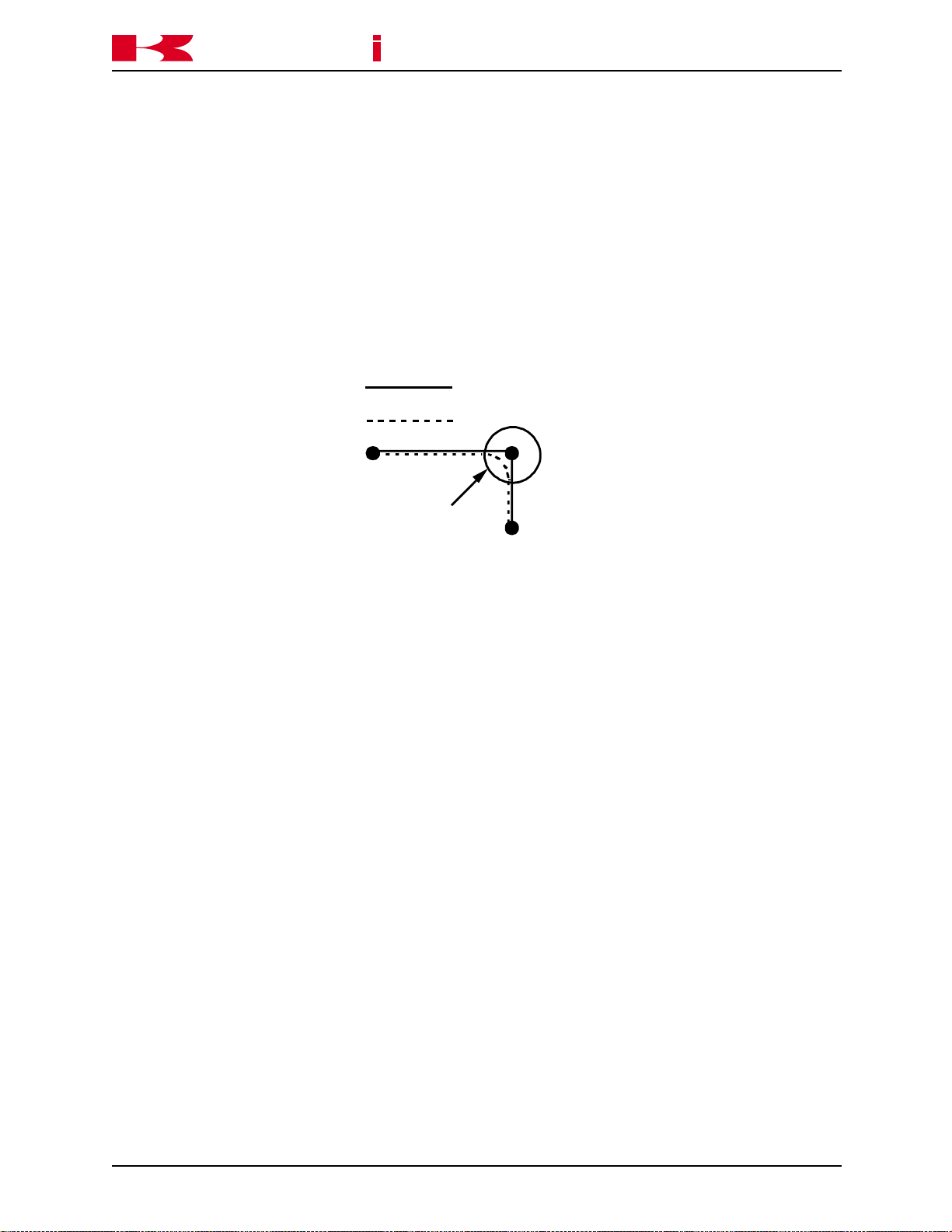
• CP
The CP switch is used to enable or disable the continuous path function. When the
switch is ON, the robot makes smooth transitions between motion segments within
the accuracy ranges set. When the switch is OFF, the robot decelerates and stops
at the end of each motion segment regardless of accuracy.
Default setting is ON
a
s
aw
k
SYSTEM OVERVIEW
Robot Path Switch Setting
AS LANGUAGE REFERENCE MANUAL
OFF
ON
Accuracy Range
Figure 1-1 CP Switch
• CYCLE.STOP
This switch is used in conjunction with an external input signal to stop the motion of
the robot. With the switch ON, when the input signal is received the robot stops and
the cycle start light turns OFF. When the program is started again it starts at the
beginning. If the program is called from another program, the program restarts at
the beginning of the main program. With the switch OFF, when the input signal is
received the robot stops and the cycle start light remains ON. The robot is in a hold
condition and when the program is started again, it continues at the point in the
cycle where it was stopped.
Default setting is OFF.
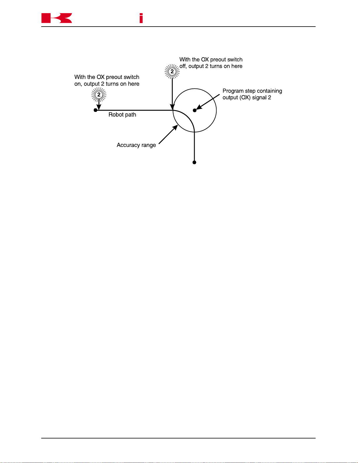
• OX.PREOUT
This switch affects the timing of output signal generation in block step programs.
When the switch is ON, an output programmed for a given point is turned ON when
the robot begins motion to the point. With the O X. PREOUT switch OFF, an output
programmed for a given point is not turned ON until the robot reaches the accuracy
range of the point. Figure 1-2 shows the effects the OX.PREOUT switch on signal
timing.
Default setting is ON.
November 14, 2000
1-3
Page 13
K
a
a
aw
k
s
SYSTEM OVERVIEW
Figure 1-2 OX.PREOUT Switch
C SERIES CONTROLLER
AS LANGUAGE REFERENCE MANUAL
• PREFETCH.SIGINS
This switch is used in conjunction with AS Language instructions and has the same
effect on signal timing as the OX.PREOUT switch has with blockstep instructions.
Default setting ON. The AS Language instructions affected are; SWAIT, TWAIT,
SIGNAL, PULSE, DLYSIG, RUNMASK, RESET and BITS.
• QTOOL
This switch allows the user to identify tools to use in block step or AS Language
programming. When the QTOOL switch is ON, nine tools are available for programming and jogging. The tool dimensions are recorded and assigned a tool number
using auxiliary function 48. When the QTOOL switch is ON, the selected tool dimensions are in effect for jogging and linear playback of block step programs.
When the QTOOL switch is OFF, the tool identified with AS Language instructions
is used.
Default setting is ON.
• REP_ONCE (Repeat Once)
When this switch is ON, programs run one time. With the switch OFF, the program
runs continuously.
Default setting is OFF.
1-4 November 14, 2000
Page 14

C SERIES CONTROLLER
K
a
• STP_ONCE (Step Once)
When this switch is ON, the repeat condition function of progressing through a
program one step at a time is active. The step forward key is used to step through a
program. When the switch is OFF, programs run continuously.
Default setting is OFF.
• AFTER.WAIT.TIMER
When this switch is ON, timers begin timing for a specified step when all wait condi-
tions are satisfied. With the switch OFF, timers begin timing when the robot reaches
coincidence of the taught point.
Default setting is OFF.
• AUTOSTART.PC
a
s
aw
k
SYSTEM OVERVIEW
AS LANGUAGE REFERENCE MANUAL
The AUTOSTART.PC, AUTOSTART2.PC, and AUTOSTART3.PC switches automatically start the associated PC program when controller power is turned on.
Default setting is OFF.
• ERRSTART.PC
When this switch is ON and specified errors (assigned dedicated signals) occur, a
PC program is run as soon as the error is detected.
Default setting is OFF.
• MESSAGES
Enables or disables message output (PRINT or TYPE) to the keyboard screen.
Default setting is ON
• RPS (Random Program Selection)
This switch enables or disables the random selection of programs based on binary
status of dedicated inputs.
Default setting is OFF
• SCREEN
This switch enables or disables scrolling of the screen when information is too large
to fit on one screen.
Default setting is ON
November 14, 2000
1-5
Page 15

C SERIES CONTROLLER
K
a
• DISPIO_01
This switch allows the user to select the type of display for viewing the status of
inputs and outputs. If the switch is ON, 1s and 0s are displayed to identify the
signal state of individual signals. A 1 represents an ON signal, while a 0 represents
an OFF signal. If the switch is off, an ON signal is represented by an O, while an X
represents a OFF signal. Dedicated signals are represented by uppercase Xs and
Os.
Default setting is OFF.
1.2 NOTATIONS AND CONVENTIONS
A mixture of uppercase and lowercase words is used throughout this manual, all key
words are shown in uppercase and all elements freely specified by the user are shown
in lowercase.
a
s
aw
k
SYSTEM OVERVIEW
AS LANGUAGE REFERENCE MANUAL
Abbreviated notations are used as well. For example, the EXECUTE command can be
abbreviated as EX.
At least one space (blank) or tab is necessary as a delimiter between the instruction (or
command) name and its arguments. The excess spaces or tabs are ignored by the
system.
Monitor commands and program instructions are processed by pressing the ENTER
key.
Many instructions or commands have arguments which can be omitted. If there is a
comma following the optional argument, the comma should be retained even if the
argument is omitted. If all successive arguments are omitted, commas may also be
omitted.
In this manual, values are expressed in decimal notations, unless noted otherwise.
Some instructions and commands require several types of arguments. Mathematical
expressions can be used to designate the value as arguments. The acceptable value
may be restricted. The following r ules show how the values are interpreted in various
cases.
• The AS
Code for Infor mation Interchange (ASCII). An ASCII character is specified by prefixing a character with an apostrophe (‘). For example, ddd = ‘A assigns 65 to ddd.
• All numerical expressions evaluated by the system result in a real value.
1-6 November 14, 2000
Language follows the conventions established by the American Standard
Page 16

C SERIES CONTROLLER
K
a
• DISTANCE is used to define the position to which the robot moves. The unit for
distance is millimeters, although units are not required to be entered with values.
Values entered for distances can be positive or negative, with their magnitudes
limited by a number representing the maximum reach of the robot. For example,
> DO DRAW 50,100,-50 moves the robot 50 mm in X, 100 mm in Y, and 50 mm in
the Z Cartesian direction.
• ANGLES in degrees are entered to define and modify orientations the robot as-
sumes at named locations, and to describe angular positions of robot joints. The
values can be positive or negative, with their magnitudes limited by 180 degrees or
360 degrees depending on the context. For example,
> DO DRIVE 2,45,75 moves joint 2 of the robot 45° at 75% of the repeat speed.
a
s
aw
k
SYSTEM OVERVIEW
AS LANGUAGE REFERENCE MANUAL
• JOINT NUMBER is an integer value from one to the number of joints available on
the robot, including a servo-controlled external axes.
• SIGNAL NUMBER is used to identify binary (on/off) signals. The value is an integer
in the range of 1-256 (output signals), 1001-1256 (input signals) depending on the
number of I/O signals available in the controller. Negative signal numbers indicate
an OFF state.
• Whenever an existing program is saved, or renamed, the new name is entered first,
followed by the old name. The above also holds true for the POINT command. For
example:
Command New Name = Old Name
SAVE Right_Side = Fender3
RENAME test = test.tmp
1.3 DISPLAYING WITH THE TERMINAL
The operator can display various types of information in the monitor mode or playback
mode. Directories and listings of programs, locations, variable data, and weld conditions
are displayed by entering specific monitor commands. For additional information, refer
to section 4.2, Program and Data Control Commands.
November 14, 2000
1-7
Page 17

C SERIES CONTROLLER
K
a
1.4 LOCATION INFORMATION
Locations recorded in the controller’s memory are comprised of values which designate
destinations for robot motion. The values recorded in memory are either Cartesian
coordinates or robot joint angles. A Car tesian coordinate represents a point in the robot
workspace with a tool center point orientation at that point. A location recorded with
joint angles specifies a robot arm configuration at that point. When the robot is directed
to move to a Cartesian location, two actions occur simultaneously: the robot is moved
so the tool center point moves to the specified point, and the tool is rotated to the prescribed orientation. When the robot is directed to move to a location recorded with joint
angles, the processor calculates a motion path based on the encoder values of the
recorded point, then moves the arm until all encoder values match those of the recorded
point. There are two types of location information, transformation locations (Cartesian
coordinates) and precision locations (joint angles).
a
s
aw
k
SYSTEM OVERVIEW
AS LANGUAGE REFERENCE MANUAL
1.4.1 PRECISION LOCATION
A precision location’s value is represented by the exact position of the individual robot
joints in degrees. There are several characteristics of precision locations that should be
considered. These characteristics result from joint angles being recorded.
Advantages of precision locations: Playback precision is achieved and there is no
ambiguity about robot configuration at a location.
Disadvantages of precision locations: The values recorded can be used by any model
of robot, however the tool center point location is different when used by a robot of
different physical size. Precision locations cannot be easily modified to compensate for
location changes in the robot workspace, because a change requires complete knowledge of the relationship between the positions of all robot joints and the locations in the
robot workspace.
1.4.2 TRANSFORMATION LOCATION
A transformation location is represented by defining the location in terms of a Cartesian
(XYZ) reference frame fixed to the base of the robot. The position of the tool center
point is defined with X, Y, and Z coordinates, and the tool orientation is defined by three
angles measured from the coordinate axes.
1-8 November 14, 2000
Page 18

C SERIES CONTROLLER
K
a
Advantages of transfor mation locations: A value defined for use with one robot can be
used with a different robot having a similar work envelope because the value is defined
in terms of workspace coordinates. Transformations are easily modified to change a
location within the robot workspace. A powerful feature of transformation locations is
the ability to define locations as combinations of values. This is called compound or
relative transfor mation. Such values are used to define the location of a part relative to
its fixturing.
Disadvantages of transfor mation locations: Since a transformation location defines the
location of the tool center point in terms of coordinates in the workspace, no information
is provided about the specific robot configuration at the location. Whenever a transformation is used to define the destination of a robot motion, the AS
the transformation location into an equivalent precision location so it knows how to move
the individual joints. This conversion can introduce small location errors. Despite these
disadvantages, transformation locations are generally much more convenient than
precision locations.
a
s
aw
k
SYSTEM OVERVIEW
AS LANGUAGE REFERENCE MANUAL
system must convert
November 14, 2000
1-9
Page 19
C SERIES CONTROLLER
K
a
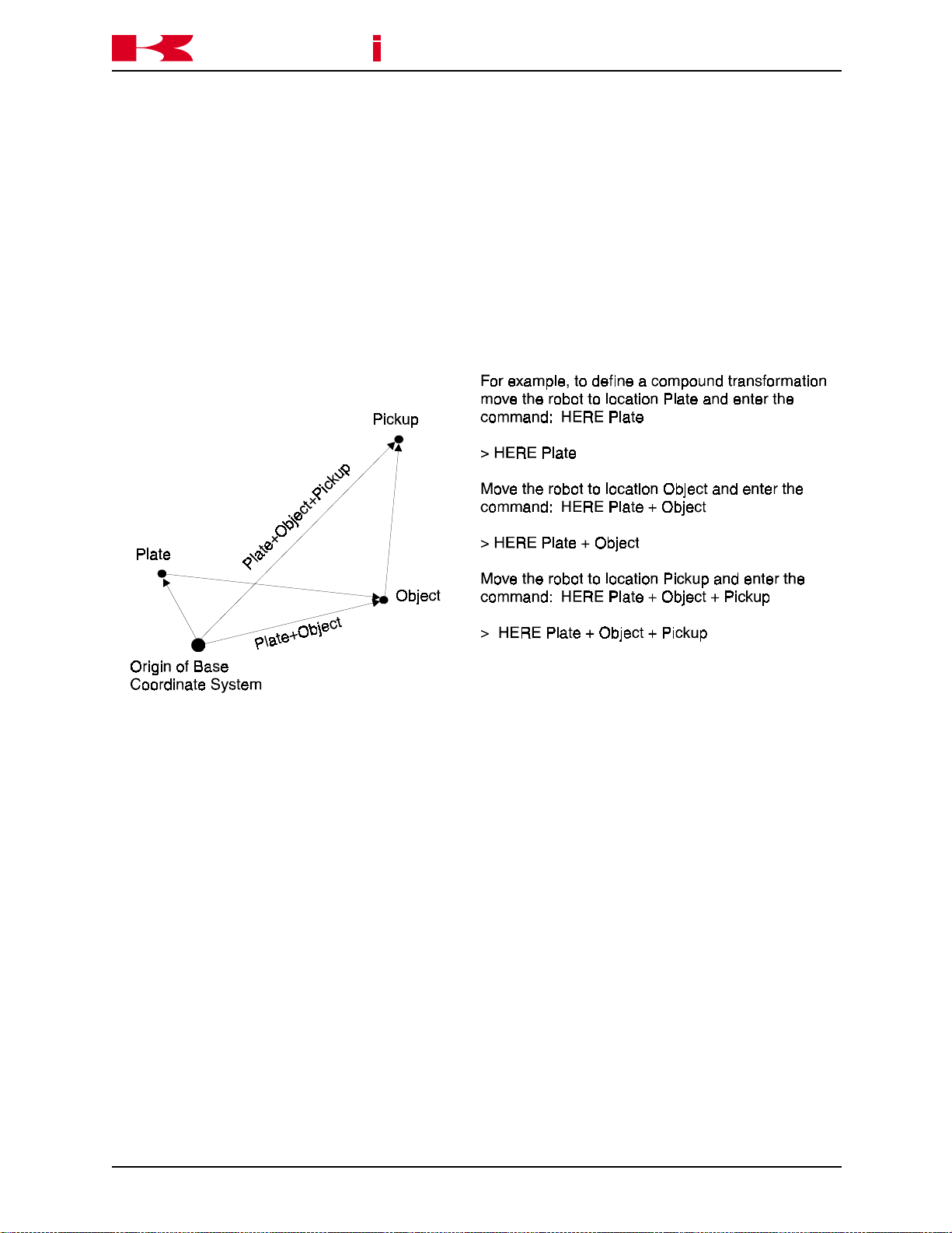
1.4.3 COMPOUND TRANSFORMATION LOCATION (RELATIVE TRANSFORMATION)
Compound transformations are defined by a combination of transformation locations,
used to create a location or locations that are relative to the first transfor mation value, in
the compound transformation (Figure 1-3).
transformation_value+transformation_value....
The last component of the compound transformation value, defines the actual location.
If the transformations are subtracted an inverse value results.
transformation - transformation
This is useful when several locations are defined relative to a reference location.
a
s
aw
k
SYSTEM OVERVIEW
AS LANGUAGE REFERENCE MANUAL
To change the location points defined relative to a reference location, only the transformation location of the reference must be updated. All locations defined relative to the
reference point are automatically changed to reflect the change.
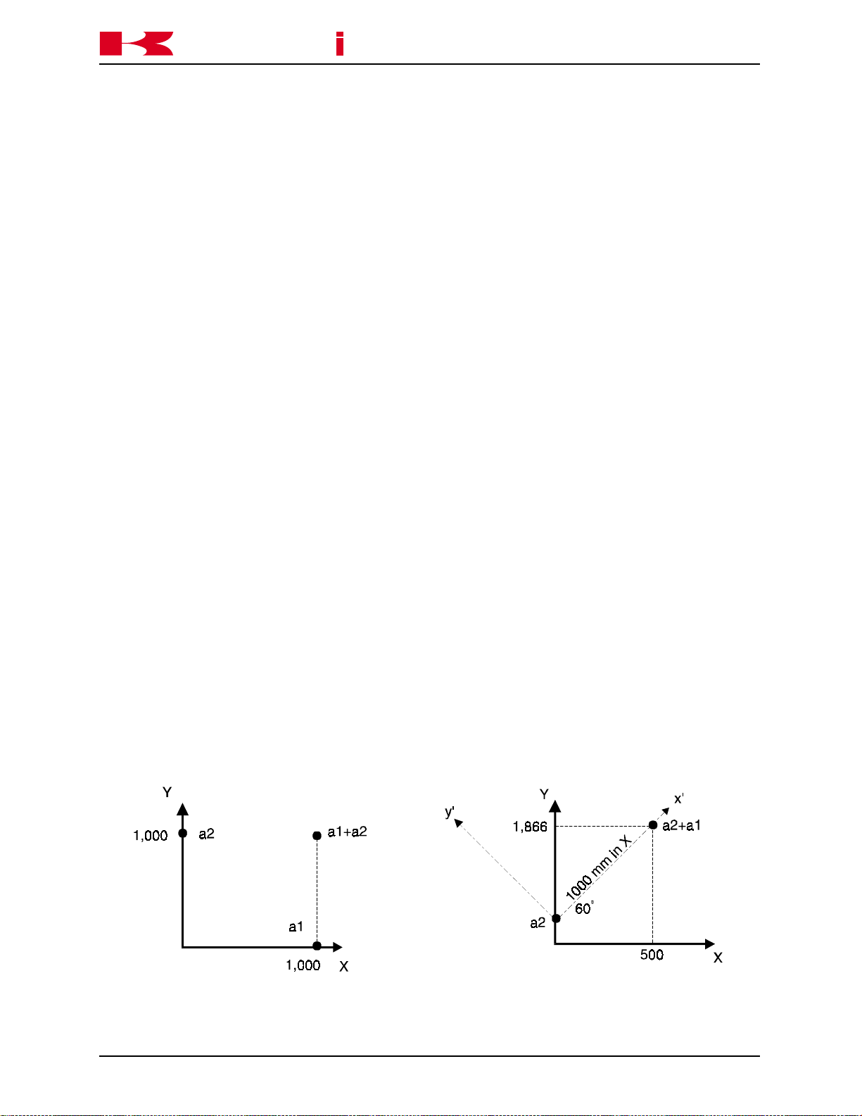
Unlike usual addition or subtraction, the commutative law does not hold true for the
transformation operation. The compound expression “loc.a + loc.b” does not necessarily
equal “loc.b + loc.a” because the turning angles O,A,T are taken into consideration. An
example of this is shown below.
Assuming: a1 = (1000, 0, 0 , 0, 0, 0)
a2 = ( 0, 1000, 0, 60, 0, 0)
a1 + a2 = (1000, 1000, 0 , 60, 0, 0)
a2 + a1 = ( 500, 1866, 0, 60, 0, 0)
1-10 November 14, 2000
Page 20
C SERIES CONTROLLER
K
a
For example, “Plate” is the name of the transformation location representing the location
of a base plate relative to the origin of the base coordinate system of the robot. “Object”
is the relative transformation for the location of an object relative to the location of the
plate. The compound transformation “Plate+Object” defines the location of the object
relative to the origin of the base coordinate system of the robot. If the transformation
location “Pickup” represents the final location relative to “Plate+Object”, the compound
transformation “Plate+Object+Pickup” defines the location of pickup relative to the origin
of the base coordinate system.
a
s
aw
k
SYSTEM OVERVIEW
AS LANGUAGE REFERENCE MANUAL
Figure 1-3 Compound Transformation
As indicated in the example above, the compound transformation is defined by a combination of several transformation values separated by “+”.
November 14, 2000
1-11
Page 21

C SERIES CONTROLLER
K
a
1.5 NUMERIC INFORMATION
Numeric information is a combination of numerals, variables, operators, and functions
which return numeric values. Numeric expressions are used not only for mathematical
calculations, but also as arguments for monitor commands or program instructions.
Numeric values used in the AS system are divided into the four types described below:
1.5.1 INTEGERS
Integers are values without fractional parts (whole numbers). Values with full precision
ranges are from -16,777,216 to +16,777,216. Values that exceed this range are
rounded to seven significant digits. Integer values are usually entered as decimal numbers, however, it may be more convenient to enter them in binary or hexadecimal notations.
a
s
aw
k
SYSTEM OVERVIEW
AS LANGUAGE REFERENCE MANUAL
1.5.2 REAL NUMBERS
Real numbers have both the integer part and a fractional part which can range from
-3.4E +38 ~ 3.4E +38. Like integers, real values are positive, zero or negative. They
can be represented in scientific notation. Real values are stored with an accuracy of
approximately seven digits, but actual values may have less precision caused by a
calculation error.
1.5.3 LOGICAL VALUES
Logical values have only two states, ON or OFF. These two states are also referred to
as TRUE and FALSE respectively. A value of negative one (-1) is assigned for the TRUE
or ON state and a value of zero (0) is assigned for the FALSE or OFF state.
NOTE
ON, OFF, TRUE, and FALSE are AS Language keywords.
> AA = ON Stores a value of -1 in variable AA
> BB = FALSE Stores a value of 0 in variable BB
> CC = -TRUE Stores a value of 1 in variable CC
1-12 November 14, 2000
Page 22

C SERIES CONTROLLER
K
a
1.5.4 ASCII VALUES
An ASCII value is the numeric value of one ASCII character. An ASCII value is specified
by prefixing the character with an apostrophe (‘).
> X = ‘A Stores a value of 65 in variable X
> X = ‘a Stores a value of 97 in variable X
1.6 VARIABLE NAMES
Variable names must start with an alphabetic character and can contain only letters,
numbers, periods, and underlines. The letters used in variable names can be entered
either in lowercase or uppercase. The length of a name is limited to fifteen characters.
AS Language
variable names because they cause ambiguity with the AS system keywords, but their
abbreviations can be used. For example, the following names cannot be used:
commands should not be used and in some cases cannot be used as
a
s
aw
k
SYSTEM OVERVIEW
AS LANGUAGE REFERENCE MANUAL
3P (first character is not alphabetic)
part#2 (“#” prefix for precision location name)
random (AS keyword)
Precision location names must be preceded by the symbol “#” to differentiate them from
transformation location names. String variables must be preceded by the symbol “$” to
differentiate them from real and transfor mation variables.
pick (transformation or real variable value)
#pick (precision value)
$count (string variable)
A transformation location and precision location may have the same name, however, the
same name may not be used for transformation values and real values. A defined
variable may be used by any program in the system.
Array variables can be used for any type of information. Arrays consist of several values
under the same name and these values are distinguished from each other by their index
value. In order to designate array elements, attach an element number (index) enclosed
by brackets to the array name. For example, “part[7]” indicates the seventh element of
the array “part”. Indexes should be integers within the range 0 to 9999.
Location, real, string, and array are four types of var iables within the AS system. These
four variable types are explained on the following pages.
November 14, 2000
1-13
Page 23

C SERIES CONTROLLER
K
a
1.6.1 LOCATION VARIABLES
A location variable (precision or transfor mation) is automatically defined when a value is
assigned for the first time. Prior to this, the location name is undefined. If a program
uses an undefined variable, an error occurs. The user defines location variables by
using monitor commands or program instructions. The following are examples of location variable values:
Precision location value: name with joint angles
#weld 90.000° 145.056° -95.098° 90.000 °45.000° 0.000°
Transformation location value: name with joint angles and turning angles
a
aw
k
s
SYSTEM OVERVIEW
JT1 JT2 JT3 JT4 JT5 JT6
AS LANGUAGE REFERENCE MANUAL
XYZOAT
weld 60.000 mm 145.050 mm -95.098 mm 90.000° 45.000° 0.000°
1.6.2 REAL VARIABLES
Real variables are defined using the assignment instruction (=). The format for assigning a real variable is:
Variable_name = numeric_value
a = 6
b = 7
c = a + b
The variable on the left side may be either a scalar variable (i.e.,“count”) or an array
element (i.e., “x [2]”). A variable is defined automatically the first time it is assigned a
value. If a program uses an undefined variable, an error occurs. The numeric value on
the right side may be a constant, a variable, or a numer ic expression. When an assignment instruction is processed, the value on the right side of the assignment instruction is
first computed, then the value is assigned to the variable on the left side.
For example, the assigned value “x=3” assigns the value 3 to the variable “x”. If a vari-
able on the left side has never been used it is defined automatically, and if it has already
been assigned a value, its current value is replaced by a new assigned value. The
above example is read as “assign 3 to x” and not “x is equal to 3”. The following ex-
ample shows this difference: x = x + 1.
1-14 November 14, 2000
Page 24

C SERIES CONTROLLER
K
a
If the example is a general equation, it is read as “x is equal to x plus 1”, which does not
make sense mathematically. It must be read as “assign the value of x plus 1 to x”. In
this case, the sum of the current value of “x” and 1 is calculated. In the next step, that
value is assigned to “x” as a new value. Therefore, the result of the above assignment
instruction is to increase the value of x by 1. In this example, the variable “x” should
have been previously defined.
x = 3
x = x + 1
In the case above, the resulting value of “x” is 4.
1.6.3 CHARACTER STRING VARIABLES
a
s
aw
k
SYSTEM OVERVIEW
AS LANGUAGE REFERENCE MANUAL
The character information referred to in the AS
characters enclosed by quotation marks (“). Since the quotation mar ks indicate the
beginning and end of a character string, they cannot be included in the string. ASCII
control characters (CTRL, CR, LF, etc.) also cannot be included in the string. For example, a command for printing (displaying on the screen) would be entered as:
PRINT “Kawasaki”
Character strings are defined by using the assignment instruction (=). The format for
assigning a character variable is :
$string_variable = string_value
(name of variable) (string expression)
The string variable on the left side may be either a scalar variable (ie., “$name”) or an
array element (ie., “$line [2]”). A variable is defined automatically the first time it is
assigned a value. If a program uses an undefined variable, an error occurs. The character string on the right side may be a constant, a string variable, or a string expression.
When an assignment instruction is processed, the value on the right side is first computed, then the value is assigned to the variable on the left side. If the var iable on the
left side has never been used, it is defined automatically, and if it has already been
used, its current value is replaced by a new assigned value.
system is indicated as a string of ASCII
November 14, 2000
1-15
Page 25

C SERIES CONTROLLER
K
a
The following is an example of string variable assignment:
In the above example, the string variable $Name is assigned the sum of $First, $Last,
and the character string “Inc.”. The command PRINT or TYPE $Name returns the string
value: Kawasaki Robotics Inc.
1.6.4 Arrays
An array is a group of values that share a single name. Location variables can be scalars or arrays. A location scalar is a single location value. Each value in an array is
called an element of the array. An element of a location array is specified in exactly the
same way as an element of a numeric array by appending an index enclosed in brackets
to the array name. For example, “part[7]” refers to element 7 of the array “part.” Indexes
must be integers in the range of 0 ~ 9999. Three examples of arrays are described
below:
a
aw
k
s
SYSTEM OVERVIEW
$First = “Kawasaki”
$Last = “ Robotics”
$Name = $First + $Last + “ Inc.”
AS LANGUAGE REFERENCE MANUAL
Example 1:
PROGRAM OUTPUT
HERE edge edge[1]=120.456
DECOMPOSE edge[1]=edge edge[2]=145.670
FOR i=1 to 6 edge[3]=-95.432
TYPE “edge[“I1,i,”]=“,/D,edge[i] edge[4]=90.456
END edge[5]=45.000
edge[6]=10.018
In the above example, the current location of the robot is defined as “edge”. The DECOMPOSE instruction extracts component values of edge (XYZOAT) consecutively (1
through 6). The program instructions between the FOR and END statements are executed repeatedly and the TYPE instruction displays the component values of edge
individually.
1-16 November 14, 2000
Page 26

C SERIES CONTROLLER
K
a
Example 2:
In the above example, the robot moves 100 mm in the X direction, a calculated amount
(10 * i + 7) mm in the Y direction, and 50 mm in the Z direction, and define the location
as weld[i].
The FOR statement, in this example increments the value of “i” in increments of two, for
example:
a
aw
k
s
SYSTEM OVERVIEW
FOR i = 2 to 6 STEP 2
DRAW 100, 10 * i + 7, 50
HERE weld[i]
END
i = 2, i = 4, i = 6.
AS LANGUAGE REFERENCE MANUAL
Example 3:
PROGRAM SUBPROGRAM OUTPUT
Main() Pg10() Corner 1
$POINT[1]=”Corner1” FOR i=1to3 edge
$POINT[2]=”edge” JMOVE weld[i] Corner2
$POINT[3]=”Corner2” TYPE$POINT[i]
CALL pg10 END
In the above example, the array is used as a string array. Each move of the robot displays the strings assigned in the main program.
1.7 NUMERICAL EXPRESSION
The numerical expression is a combination of numeric values and variables combined
together with operators. The expressions are completed by the addition of functional
modifiers to the numeric values and variables. All numerical expressions evaluated by
the system result in a real value. The interpretation of the value depends on the context
in which the expression appears. For example, an expression specified for an array
index is interpreted as yielding an integer value.
1.7.1 OPERATORS
For describing expressions, ar ithmetic, logical, and binary, operators are provided. All of
these operators combine two values to obtain a single resulting value, except three: the
two operators (NOT and COM) operate on a single value and the operator (-) operates
on one or two values. The operators are described on the following page.
November 14, 2000
1-17
Page 27

K
a
Arithmetic Operators: + addition
Relational Operator: < less than
a
s
aw
k
SYSTEM OVERVIEW
- subtraction or negation
* multiplication
/ division
^ power (if a
x=(-2)^2 results in an error
x= -2^2 assigns -4 to x
MOD remainder
x=5 MOD 2 assigns the remainder of 5/2 (1
in this case) to x
<=, (=<) less than or equal to
== equal to
<> not equal to
>=, (=>) greater than or equal to
> greater than
C SERIES CONTROLLER
AS LANGUAGE REFERENCE MANUAL
b
, a<0 results in error)
Logical Operator: AND logical AND
NOT logical complement
OR logical OR
XOR exclusive logical OR
The logical operators are used in Boolean operations such as logical OR (0+1=1,
1+1=1, 0+0=0), logical AND (0x1=0, 1x1=1, 0x0=0), and logical XOR (0+1=1, 1+1=0,
0+0=0). The logical operators are not used for calculating numeric values, but for determining the logical state (TRUE or FALSE) of the conditional expression. If a numeric
value is zero (0), it is considered to be FALSE (0). All nonzero values are considered to
be TRUE(-1).
OPERATION RESULT
0 AND 0 0 (FALSE)
1 AND 1 -1 (TRUE)
1 OR 0 -1 (TRUE)
1-18 November 14, 2000
Page 28

C SERIES CONTROLLER
K
a
Binary Operator: BAND Binary AND
The binary logical operators perform logical operations for each respective bit of two
numeric values.
OPERATION RESULT
5 BOR 3 7
0101 BOR 0011 0111
5 BAND 9 1
0101 BAND 1001 0001
a
aw
k
s
SYSTEM OVERVIEW
BOR Binary OR
BXOR Binary XOR
COM Binary Complement
AS LANGUAGE REFERENCE MANUAL
Expressions are evaluated according to a sequence of pr iorities. Parentheses can be
used to group the components of an expression and to control the order in which the
operations are performed. When expressions containing parentheses are evaluated, the
expression within the innermost pair is evaluated first, then the system works toward the
outermost pair. Within parentheses, expressions are evaluated in the following order:
1. Evaluate functions and arrays.
2. Process power operator “ ^ ”.
3. Process unary operators “ - ” (single component).
4. Process multiplication “ * ” and division “ / ” operators from left to right.
5. Calculate remainders (MOD operators) from left to right.
6. Process addition “ + ” and subtraction “ - ” operators from left to right.
7. Process relational operators from left to right.
8. Process COM operators from left to right.
9. Process BAND operators from left to right.
10. Process BOR operators from left to r ight.
11. Process BXOR operators from left to r ight.
12. Process NOT operators from left to right.
13. Process AND operators from left to r ight.
14. Process OR operators from left to r ight.
15. Process XOR operators from left to r ight.
The logical expressions result in a logical value TRUE or FALSE. A logical expression
can be used as a condition in which the execution of a program or program steps is
performed. When evaluating logical expressions, the value zero is considered FALSE
and all nonzero values are considered TRUE. Therefore, all real values or real value
expressions can be used as a logical value.
November 14, 2000
1-19
Page 29

C SERIES CONTROLLER
K
a
For example, the following two statements have the same meaning, but the second
statement is easier to understand.
IF x GOTO 10 (If the value of x is true, goto label 10 in the program)
IF x <> 0 GOTO 10 (If the value of x is not equal to 0, goto label 10 in the program)
1.8 MONITOR COMMANDS
TEACH location variable name
The TEACH command is used in conjunction with the small teach pendant. With the
small teach pendant connected, the TEACH command is entered at the monitor prompt.
The small teach pendant is used to jog the robot to the locations used in the specified
program. When the RECORD key on the teach pendant is pressed, the location is
placed into the system memory with the specified location variable name
0. Each time the RECORD key is pressed the number following the location variable
name is increased by one.
a
s
aw
k
SYSTEM OVERVIEW
AS LANGUAGE REFERENCE MANUAL
followed by a
For example, the command TEACH loc is entered at the monitor prompt, the first time
the RECORD key on the small teach pendant is pressed, a location with the name loc0
is stored in the system memory. The next time the RECORD key of the small teach
pendant is pressed, the location stored in system memory is loc1
The TEACH command allows the programmer to record transfor mation locations without
having to exit the work cell for each new location.
The HERE command stores the current robot location in the specified precision or
transformation variable.
HERE #pallet
The POINT command defines the named location variable using an existing location
variable. Component values may also be entered from the keyboard.
POINT a = b
Assigns component values of location var iable b into location variable a.
POINT #a
.
Displays the current component of location variable #a. If the location variable is not
defined, zeros are displayed.
1-20 November 14, 2000
Page 30

C SERIES CONTROLLER
K
a
1.8.1 PROGRAM INSTRUCTIONS
The commands HERE and POINT may also be used in a program as program instr uctions. For example,
JMOVE loc1
POINT loc2=loc1
DRAW 347.28, ,479.0
HERE loc3
In the above example, the robot moves to loc1. The POINT command then assigns
component values of loc1 to loc2. The DRAW command moves the robot 347.28 mm in
X, and 479 mm in the Z direction. Finally, loc3 is defined by the HERE command.
a
s
aw
k
SYSTEM OVERVIEW
AS LANGUAGE REFERENCE MANUAL
November 14, 2000
1-21
Page 31

C SERIES CONTROLLER
K
a
2.0 SAFETY ........................................................................................................... 2-2
2.1 Introduction....................................................................................................... 2-2
2.2 Safety Conventions and Symbology................................................................. 2-3
2.2.1 Warning/Caution Symbols ................................................................................ 2-3
2.3 Safety Categories............................................................................................. 2-4
2.3.1 Personal Safety ................................................................................................ 2-4
2.3.2 Safety During Operation ................................................................................... 2-6
2.3.3 Safety During Programming ............................................................................. 2-7
2.3.4 Safety During Inspection and Maintenance...................................................... 2-8
2.4 Safety Features ................................................................................................ 2-9
2.5 Work Envelope Drawings ............................................................................... 2-10
2.5.1 FS02N/FS03N................................................................................................ 2-10
2.5.2 FS06L............................................................................................................. 2-11
2.5.3 FC06N/FS06N/FW06N/FS10C....................................................................... 2-12
2.5.4 FS10N ............................................................................................................ 2-13
2.5.5 FS10E ............................................................................................................ 2-14
2.5.6 FS10L............................................................................................................. 2-15
2.5.7 FS20C ............................................................................................................ 2-16
2.5.8 FS20N ............................................................................................................ 2-17
2.5.9 FS30L............................................................................................................. 2-18
2.5.10 FS30N/FS45C ................................................................................................ 2-19
2.5.11 FS45N ............................................................................................................ 2-20
2.5.12 UB150 ............................................................................................................ 2-21
2.5.13 UT100/150/200............................................................................................... 2-22
2.5.14 UX70 .............................................................................................................. 2-23
2.5.15 UX100/120/150 .............................................................................................. 2-24
2.5.16 UX200 ............................................................................................................ 2-25
2.5.17 UX300 ............................................................................................................ 2-26
2.5.18 UZ100/120/150............................................................................................... 2-27
2.5.19 ZD130............................................................................................................. 2-28
2.5.20 ZX130L........................................................................................................... 2-29
2.5.21 ZX130U .......................................................................................................... 2-30
2.5.22 ZX165U .......................................................................................................... 2-31
2.5.23 ZX200S .......................................................................................................... 2-32
2.5.24 ZX200U .......................................................................................................... 2-33
2.5.25 ZX300S .......................................................................................................... 2-34
a
s
aw
k
SAFETY
AS LANGUAGE REFERENCE MANUAL
November 14, 2000
2-1
Page 32

C SERIES CONTROLLER
K
a
2.0 SAFETY
2.1 INTRODUCTION
Safety is an important consideration in the use of automated and robotic equipment in
the industrial environment. All operators, maintenance personnel, and programmers
must be aware of all automated equipment, peripheral and robotic equipment that
occupies the work cell, and their associated operational and maintenance procedures.
For this reason it is recommended that all personnel who operate, maintain, and
program Kawasaki robots, attend a Kawasaki approved training course that would be
pertinent to each employee’s specific job responsibilities.
The following safety sections in this text are designed to support and augment existing
safety guidelines that may be in use in your plant, and/or are provided by municipal,
state, or federal governments, but are NOT designed to supplant or supersede any
existing rules, regulations, or guidelines that may be in use. Because safety is the
primary responsibility of the user, owner, and/or employer, Kawasaki recommends that
specific safety guidelines and recommendations be adopted from groups or individuals
that are professionals in safety design and implementation.
a
s
aw
k
SAFETY
AS LANGUAGE REFERENCE MANUAL
Two recommended sources for national and federal safety laws and regulations are:
1. OCCUPATIONAL SAFETY AND HEALTH STANDARDS, available from:
U.S. Department of Labor
Occupational Safety & Health Administration
Office of Public Affairs - Room N3647
200 Constitution Avenue
Washington, DC 20210
http://www.osha-slc.gov/SLTC/robotics/index.html
2. AMERICAN NATIONAL STANDARD FOR INDUSTRIAL ROBOTS AND ROBOT
SYSTEMS-SAFETY REQUIREMENTS (ANSI/RIA R15.06-1992), available from:
American National Standards Institute
11 West 42nd Street
New York, NY 10036
http://www.ansi.org/
All safety related issues and descriptions, either presented in written or oral form from
any representative of Kawasaki Robotics (USA), Inc., are intended to provide general
safety precautions and procedures and, therefore, are not intended to provide all safety
measures necessary for the protection of all personnel in the work environment.
2-2 November 14, 2000
Page 33

C SERIES CONTROLLER
K
a
Kawasaki robots are considered safe for use in industrial environments when all safety
guidelines are adhered to. Adherence to the safety guidelines for safe robot operation
and the protection of personnel and equipment is the responsibility of the end user.
2.2 SAFETY CONVENTIONS AND SYMBOLOGY
2.2.1 WARNING/CAUTION SYMBOLS
The following symbol is present in all Kawasaki Robotics (USA), Inc. documentation to
signify to the user that proper guidelines, as set forth in the text, are designed to provide
pertinent information for the protection of personnel:
a
s
aw
k
SAFETY
AS LANGUAGE REFERENCE MANUAL
! WARNING
This warning symbology is used in all Kawasaki Robotics (USA), Inc. documentation to identify processes or
procedures, that if not followed properly, may result in
serious injury or death to personnel.
The following symbol is present in all Kawasaki Robotics (USA), Inc. documentation to
signify to the user that proper guidelines as set forth, are designed to provide pertinent
information for the protection of robotic related equipment:
! CAUTION
This caution symbology is used in all Kawasaki Robotics (USA), Inc. documentation to identify processes or
procedures, that if not followed properly, may result in
damage to robotic or peripheral equipment.
November 14, 2000
2-3
Page 34

K
a
2.3 SAFETY CATEGORIES
Personnel safety can be described in one of four categories:
• Personal safety
• Safety during operation
• Safety during programming
• Safety during inspection and maintenance
A description of each follows in this section.
2.3.1 PERSONAL SAFETY
a
s
aw
k
SAFETY
AS LANGUAGE REFERENCE MANUAL
C SERIES CONTROLLER
Safety procedures must be an integral part of operational procedures for the operator,
programmer, and maintenance person. These procedures must be followed explicitly
and on a regular basis. Safety procedures are followed on a daily basis, they should
become a regular part of everyday operational procedures, which are designed to
protect the user. Some guidelines are presented in brief in the following section:
• Before operating or maintaining the robot or robot controller, be sure you fully
understand and comprehend ALL maintenance, operating, and programming
procedures, and ensure that ALL safety related precautions are taken and complied
with before these procedures are attempted.
• AVOID wearing loose clothing, scarves, wrist watches, rings, and jewelry when
working on the controller and robot. It is also recommended that if ties must be
worn in your shop environment that they be the clip-on var iety rather than tied ties.
• ALWAYS wear safety glasses or goggles and approved safety shoes for your shop
conditions. Follow all applicable OSHA, NIOSHA, MSHA, local, state, federal, and
plant safety specifications and procedures.
• Know the ENTIRE work cell or area that the robot occupies.
• Be aware of the ENTIRE work envelope of the robot and any peripheral devices.
• Locate ALL emergency stop buttons or switches.
• AVOID trap points in which personnel could become trapped between a moving
device and any stationary devices.
2-4 November 14, 2000
Page 35

C SERIES CONTROLLER
K
a
• Personnel should NEVER enter the work envelope during automatic operations.
• Ensure that ALL personnel are clear of the work envelope before initiating any
motion commands for the robot.
• Before initiating any motion commands, KNOW beforehand how the robot will
perform when that command is given.
• Be sure that the ENTIRE work area is free of any debris, tools, fixturing, lubricants,
and cleaning equipment before operation of the robot is attempted.
• If any personnel observe unsafe working conditions, report them IMMEDIATELY to
your supervisor or plant safety coordinator.
• ALL personnel should identify by name and function ALL switches, indicators, and
control signals that could initiate robot motion.
a
s
aw
k
SAFETY
AS LANGUAGE REFERENCE MANUAL
• NEVER defeat, render useless, jumper out, or bypass any safety related device,
whether mechanical or electrical in design.
• ALL safety devices approved for use in your plant must be properly installed and
maintained to ensure personnel safety.
• NEVER attempt to stop or brake the robot during operation with your body or person.
• ONLY utilize E-stops to stop robot motion in emergency situations.
November 14, 2000
2-5
Page 36

C SERIES CONTROLLER
K
a
2.3.2 SAFETY DURING OPERATION
• During operation of the robot, identify the maximum reach of the robot in ALL
directions, which is referred to as the work envelope.
• ALWAYS keep your work area clean and free of any debris which includes, but
is not limited to, oil, water, tool, fixturing, electronic test equipment, etc.
• During operations that involve the teach pendant, the ONLY person allowed in
the work envelope is the teacher, or the person operating the teach pendant.
The teach pendant has provisions to protect the operator. These safety
provisions include an E-stop, trigger switch, and deadman switch.
• NEVER block the operator’s path of retreat.
a
s
aw
k
SAFETY
AS LANGUAGE REFERENCE MANUAL
• During the teach operation of the robot ALWAYS have a path of retreat planned.
• AVOID pinch points.
2-6 November 14, 2000
Page 37

C SERIES CONTROLLER
K
a
2.3.3 SAFETY DURING PROGRAMMING
• During operation of the robot, be sure you are able to identify the maximum
reach of the robot in ALL directions, which is referred to as the work envelope.
• During teach operations the ONLY person allowed in the work envelope is the
teacher, or the person operating the teach pendant. The teach pendant has
provisions to protect the operator including E-stop, trigger switch, and deadman
switch.
• AVOID pinch points.
• During point-to-point playback operations, be aware that the robot is ONLY
cognizant of its present location and the next point it is requested to move to.
It will execute this move with total disregard to what may lie in its path when
the move is executed.
a
s
aw
k
SAFETY
AS LANGUAGE REFERENCE MANUAL
• Playback accuracy and speed can affect the geometry of the path coordinates.
Therefore, when changing accuracy or speed, ALWAYS test run the program at
a slow speed or point-to-point mode before attempting the continuous path
operation in the repeat mode.
• ALWAYS test run a new path program at a reduced speed or in point-to-point
mode prior to attempting a high-speed playback operation in the repeat mode.
November 14, 2000
2-7
Page 38

C SERIES CONTROLLER
K
a
2.3.4 SAFETY DURING INSPECTION AND MAINTENANCE
Before entering the work envelope to perform either inspection or maintenance
procedures, turn off 3-phase power on the disconnect and tag and lockout the
disconnect switch.
a
s
aw
k
SAFETY
AS LANGUAGE REFERENCE MANUAL
! WARNING
The input side (top) of the controller disconnect may still
be live when the controller disconnect is turned OFF. If
work is to be performed at the controller disconnect
switch, turn OFF the 3-phase power at the source, and
tag and lockout the source disconnect.
• When removing an axis motor, be aware that the axis WILL fall if left unsupported.
The brake assembly is in the servo drive motor, therefore, the axis of the robot will
be unsupported if removed.
• When using the axis brake release switches in the controller, be aware that the axis
MAY fall if left unsupported.
• Before working on pneumatic or high pressure water supplies, turn off supply
pressure and purge ALL lines to remove any residual pressure.
• Assign ONLY qualified personnel to perform all maintenance procedures.
• Consult ALL available documentation before attempting any repair or service
procedures.
• Use ONLY replacement parts approved by Kawasaki Robotics (USA), Inc.
• BEFORE attempting to adjust or repair a device in the robot controller that may
have yellow interlock control circuit wires attached, locate the source of the power
and remove it by disconnecting the appropriate disconnect at its source.
• During inspection and maintenance procedures, if your installation is equipped
with safety fences and safety plugs, REMOVE and HOLD the safety plug while
performing these operations. In addition, the safety procedures outlined above
should be adhered to.
2-8 November 14, 2000
Page 39

C SERIES CONTROLLER
K
a
2.4 SAFETY FEATURES
To safeguard the user, the Kawasaki robot system is equipped with many safety
features. These safety items include:
• All E-stops are hard-wired.
• The multi function panel, small teach pendant, and operation panel are equipped
with red mushroom-type detented E-stop push buttons. If an optional interface
panel is installed, the E-stop from the operation panel is relocated to the optional
interface panel.
• All robot axes are monitored by the robot controller for velocity and deviation errors.
• Robot velocities are constantly monitored by software. Should an over-velocity
condition be detected, the robot will fault in a velocity error condition.
a
s
aw
k
SAFETY
AS LANGUAGE REFERENCE MANUAL
• Teach velocities and check mode velocities are limited to a maximum of 250
mm/sec (9.843 in/sec).
• All robot axes have software limits.
• JT1 is equipped with overtravel limit switches (JT2 and JT3 are optional).
• All F-series, U-series, and Z-series mechanical units have overtravel hardstops on
the JT1, JT2, JT3, and JT5 axes.
• All robot axes are equipped with 24 VDC electromechanical brakes. Should the
robot lose line power, the robot arm will not drop because the brakes are engaged
when power is OFF at the robot controller.
November 14, 2000
2-9
Page 40

K
a
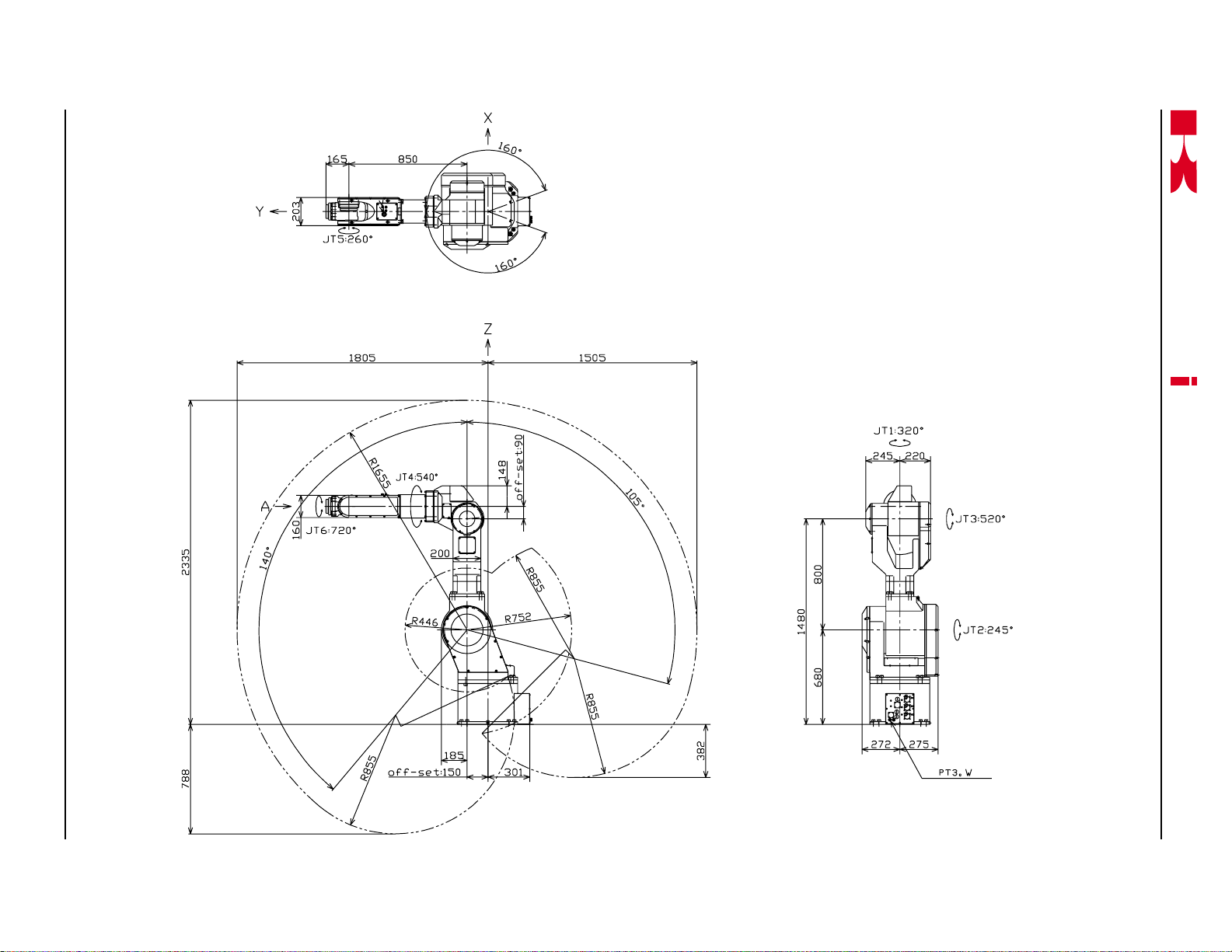
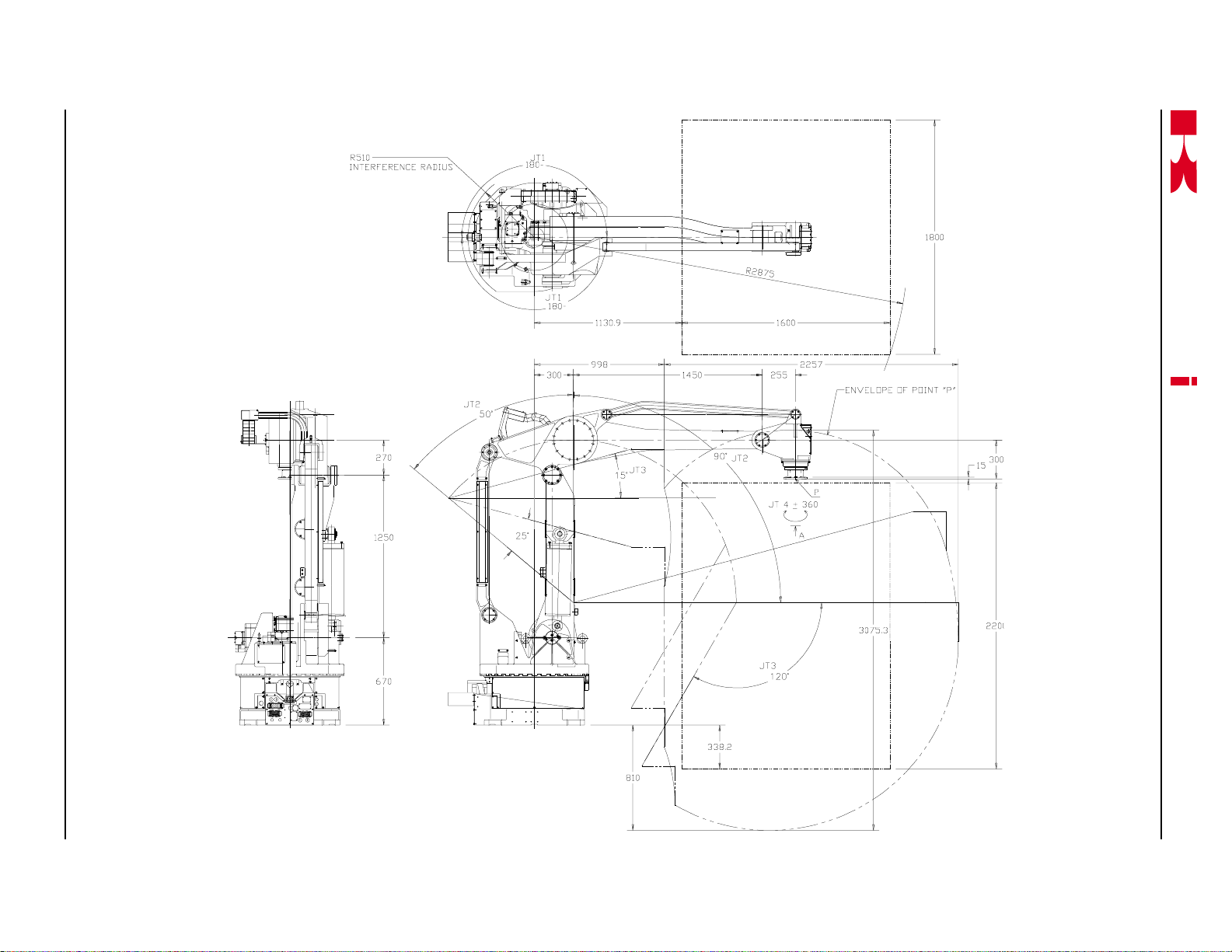
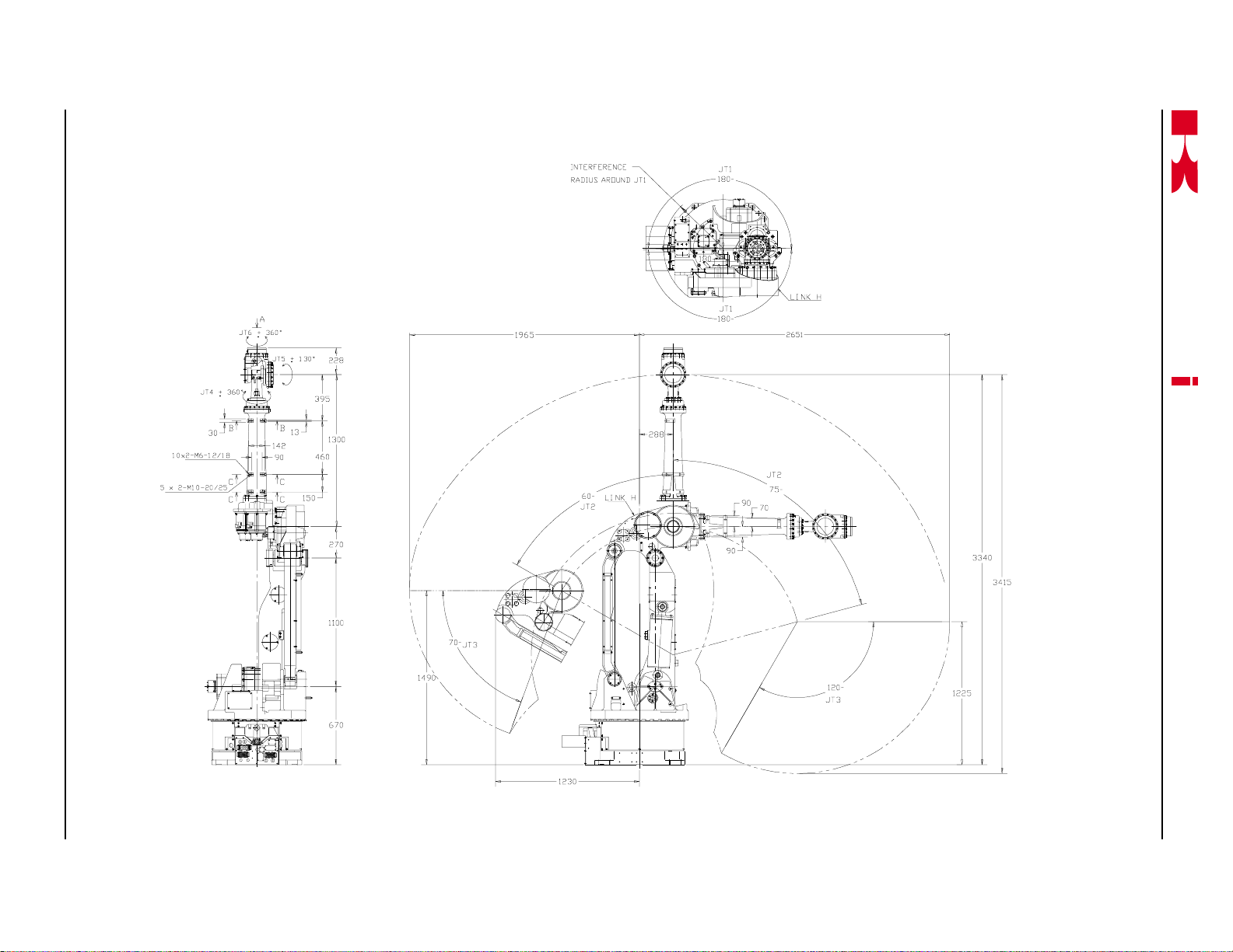
2.5 WORK ENVELOPE DRAWINGS
2.5.1 FS02N/FS03N
a
s
aw
k
C SERIES CONTROLLER
AS LANGUAGE REFERENCE MANUAL
SAFETY
Figure 2-1 FS02N/FS03N Work Envelope
2-10 November 14, 2000
Page 41

November 14, 2000
Figure 2-2 FS06L Work Envelope
2.5.2 FS06L
K
a
a
s
aw
k
SAFETY
2-11
AS LANGUAGE REFERENCE MANUAL
C SERIES CONTROLLER
Page 42
2-12 November 14, 2000
2.5.3 FC06N/FS06N/FW06N/FS10C
K
Figure 2-3 FC06N/FS06N/FW06N/FS10C Work Envelope
a
a
s
aw
k
SAFETY
AS LANGUAGE REFERENCE MANUAL
C SERIES CONTROLLER
Page 43

November 14, 2000
Figure 2-4 FS10N Wor k Envelope
2.5.4 FS10N
K
a
a
s
aw
k
SAFETY
2-13
AS LANGUAGE REFERENCE MANUAL
C SERIES CONTROLLER
Page 44

2-14 November 14, 2000
Figure 2-5 FS10E Wor k Envelope
2.5.5 FS10E
K
a
a
s
aw
k
SAFETY
AS LANGUAGE REFERENCE MANUAL
C SERIES CONTROLLER
Page 45
November 14, 2000
Figure 2-6 FS10L Work Envelope
2.5.6 FS10L
K
a
a
s
aw
k
SAFETY
2-15
AS LANGUAGE REFERENCE MANUAL
C SERIES CONTROLLER
Page 46

2-16 November 14, 2000
Figure 2-7 FS20C Work Envelope
2.5.7 FS20C
K
a
a
s
aw
k
SAFETY
AS LANGUAGE REFERENCE MANUAL
C SERIES CONTROLLER
Page 47

November 14, 2000
Figure 2-8 FS20N Wor k Envelope
2.5.8 FS20N
K
a
a
s
aw
k
SAFETY
2-17
AS LANGUAGE REFERENCE MANUAL
C SERIES CONTROLLER
Page 48
2-18 November 14, 2000
Figure 2-9 FS30L Work Envelope
2.5.9 FS30L
K
a
a
s
aw
k
SAFETY
AS LANGUAGE REFERENCE MANUAL
C SERIES CONTROLLER
Page 49

November 14, 2000
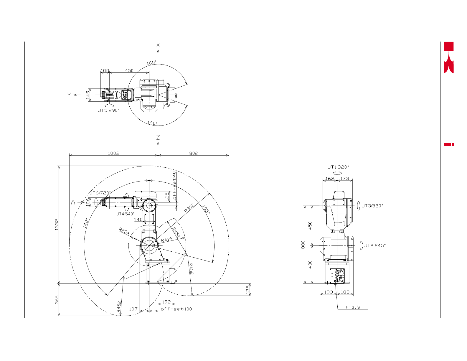
2.5.10 FS30N/FS45C
K
a
Figure 2-10 FS30N/FS45C Work Envelope
a
s
aw
k
SAFETY
AS LANGUAGE REFERENCE MANUAL
C SERIES CONTROLLER
2-19
Page 50
2-20 November 14, 2000
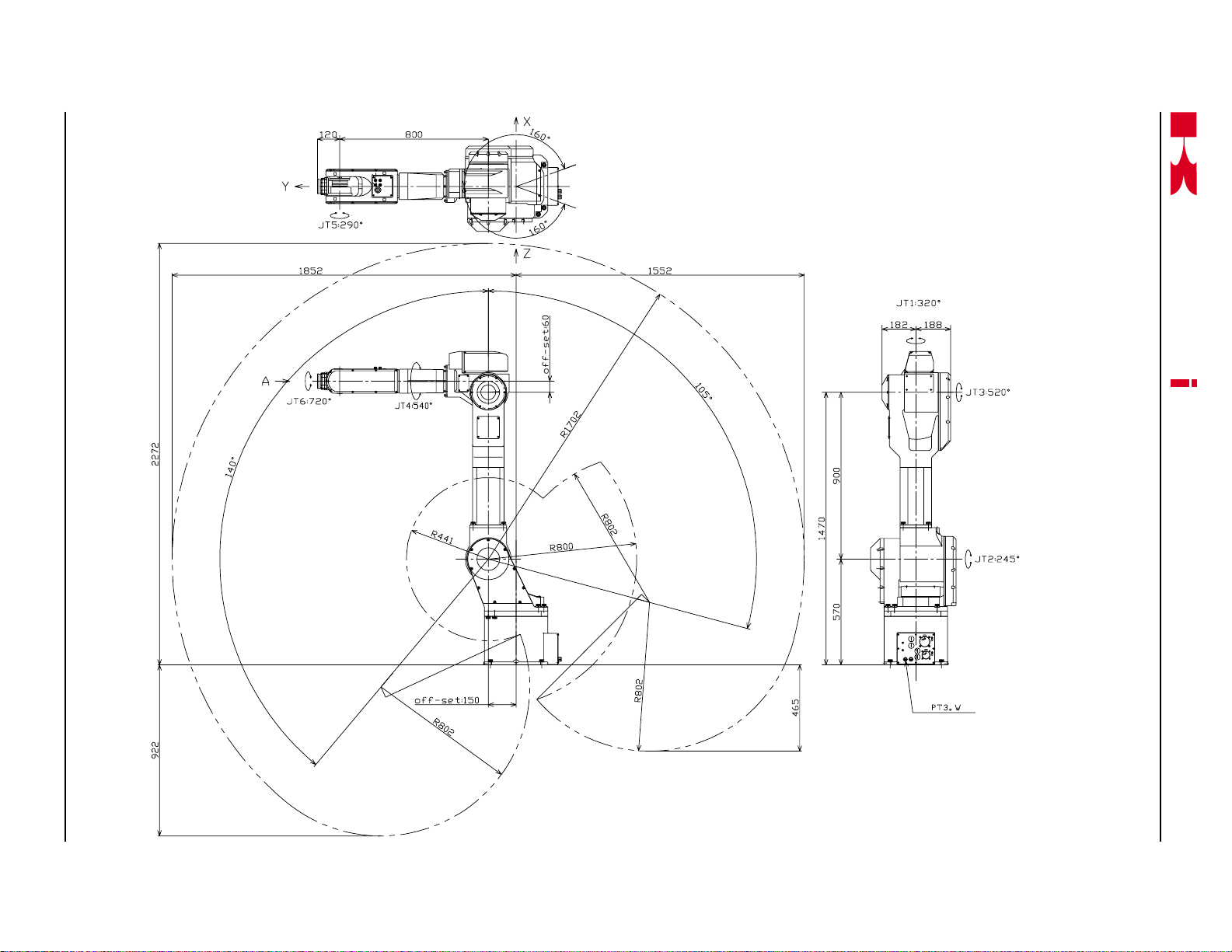
Figure 2-11 FS45N Work Envelope
2.5.11 FS45N
K
a
a
s
aw
k
SAFETY
AS LANGUAGE REFERENCE MANUAL
C SERIES CONTROLLER
Page 51

K
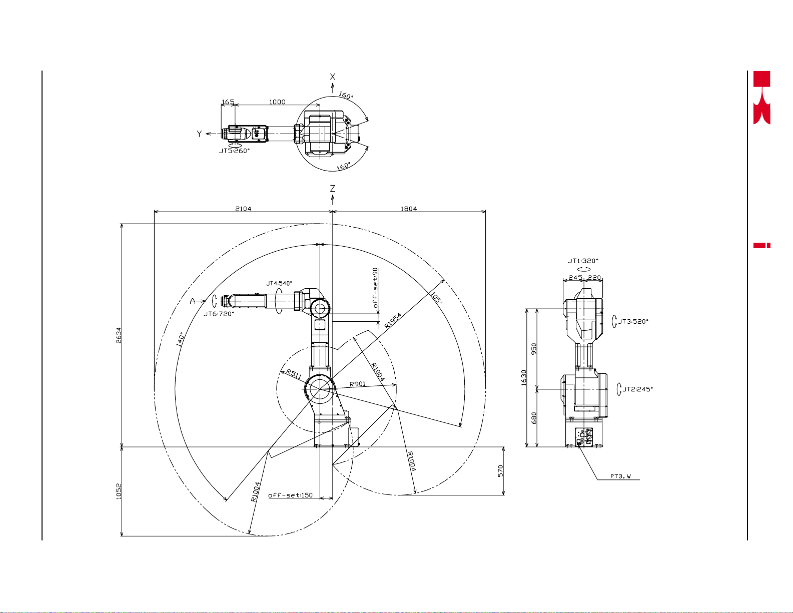
2.5.12 UB150
a
a
s
C SERIES CONTROLLER
aw
k
SAFETY
AS LANGUAGE REFERENCE MANUAL
November 14, 2000
Figure 2-12 UB150 Work Envelope
2-21
Page 52

K
a
2.5.13 UT100/150/200
a
s
C SERIES CONTROLLER
aw
k
SAFETY
AS LANGUAGE REFERENCE MANUAL
Figure 2-13 UT100/120/150 Work Envelope
2-22 November 14, 2000
Page 53

November 14, 2000
Figure 2-14 UX70 Work Envelope
2.5.14 UX70
K
a
a
s
aw
k
SAFETY
2-23
AS LANGUAGE REFERENCE MANUAL
C SERIES CONTROLLER
Page 54

2-24 November 14, 2000
2.5.15 UX100/120/150
K
a
Figure 2-15 UX100/120/150 Work Envelope
a
s
aw
k
SAFETY
AS LANGUAGE REFERENCE MANUAL
C SERIES CONTROLLER
Page 55

November 14, 2000
Figure 2-16 UX200 Work Envelope
2.5.16 UX200
K
a
a
s
aw
k
SAFETY
2-25
AS LANGUAGE REFERENCE MANUAL
C SERIES CONTROLLER
Page 56

2-26 November 14, 2000
Figure 2-17 UX300 Work Envelope
2.5.17 UX300
K
a
a
s
aw
k
SAFETY
AS LANGUAGE REFERENCE MANUAL
C SERIES CONTROLLER
Page 57

November 14, 2000
2.5.18 UZ100/120/150
K
a
Figure 2-18 UZ100/120/150 Wor k Envelope
a
s
aw
k
SAFETY
AS LANGUAGE REFERENCE MANUAL
C SERIES CONTROLLER
2-27
Page 58
2-28 November 14, 2000
Figure 2-19 ZD130 Work Envelope
2.5.19 ZD130
K
a
a
s
aw
k
SAFETY
AS LANGUAGE REFERENCE MANUAL
C SERIES CONTROLLER
Page 59

November 14, 2000
Figure 2-20 ZX130L Work Envelope
2.5.20 ZX130L
K
a
a
s
aw
k
SAFETY
2-29
AS LANGUAGE REFERENCE MANUAL
C SERIES CONTROLLER
Page 60
2-30 November 14, 2000
Figure 2-21 ZX130U Work Envelope
2.5.21 ZX130U
K
a
a
s
aw
k
SAFETY
AS LANGUAGE REFERENCE MANUAL
C SERIES CONTROLLER
Page 61

November 14, 2000
Figure 2-22 ZX165U Work Envelope
2.5.22 ZX165U
K
a
a
s
aw
k
SAFETY
2-31
AS LANGUAGE REFERENCE MANUAL
C SERIES CONTROLLER
Page 62

2-32 November 14, 2000
Figure 2-23 ZX200S Work Envelope
2.5.23 ZX200S
K
a
a
s
aw
k
SAFETY
AS LANGUAGE REFERENCE MANUAL
C SERIES CONTROLLER
Page 63

November 14, 2000
Figure 2-24 ZX200U Work Envelope
2.5.24 ZX200U
K
a
a
s
aw
k
SAFETY
2-33
AS LANGUAGE REFERENCE MANUAL
C SERIES CONTROLLER
Page 64

2-34 November 14, 2000
Figure 2-25 ZX300S Work Envelope
2.5.25 ZX300S
K
a
a
s
aw
k
SAFETY
AS LANGUAGE REFERENCE MANUAL
C SERIES CONTROLLER
Page 65

C SERIES CONTROLLER
K
a
3.0 POWER ON/OFF PROCEDURES ..................................................................... 3-2
3.1 Controller Power On/Off Procedures.................................................................. 3-2
3.1.1 Controller Power On Procedures ....................................................................... 3-2
3.1.2 Controller Power Off Procedures ....................................................................... 3-2
3.2 Servo Motor Power-On Procedures ................................................................... 3-7
3.2.1 Servo Motor Power-On in the Repeat Mode ...................................................... 3-7
3.2.2 Servo Motor Power-On in the Teach Mode......................................................... 3-7
3.3 Methods for Stopping the Robot ........................................................................ 3-8
3.3.1 Emergency Stop Switch..................................................................................... 3-8
3.3.2 HOLD/RUN Switch............................................................................................. 3-8
3.3.3 TEACH/REPEAT Switch .................................................................................... 3-8
a
aw
k
s
POWER ON/OFF PROCEDURES
AS LANGUAGE REFERENCE MANUAL
November 20, 1998
3-1
Page 66

C SERIES CONTROLLER
K
a
3.0 POWER ON/OFF PROCEDURES
This unit provides the power ON/OFF procedures for the robot controller and servo
motors. Refer to figures 3-1 through 3-7 during these procedures.
3.1 CONTROLLER POWER ON/OFF PROCEDURES
3.1.1 CONTROLLER POWER ON PROCEDURES
1. Ensure all personal are clear of the work cell and all safety devices are in place and
operational.
2. Turn the HOLD/RUN switch to the HOLD position.
3. Place the controller main disconnect switch in the ON position. At this time the
CONTROL POWER indicator lamp illuminates.
a
aw
k
s
POWER ON/OFF PROCEDURES
AS LANGUAGE REFERENCE MANUAL
3.1.2 CONTROLLER POWER OFF PROCEDURES
1. Turn the HOLD/RUN switch to the HOLD position; the robot decelerates to a stop
and the MOTOR POWER lamp turns off.
2. Press the EMERGENCY STOP switch. At this time the CYCLE START lamp turns
off.
3. Place the controller main disconnect switch in the OFF position.
3-2
November 14, 2000
Page 67
K
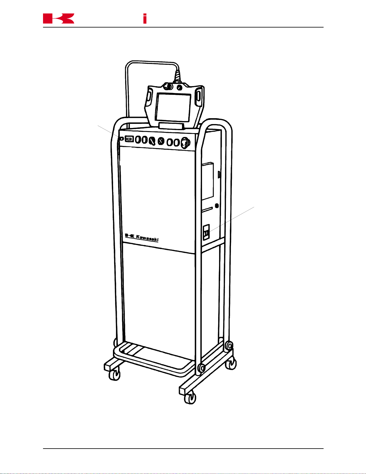
t
a
Control Power
Indicator
a
aw
k
s
POWER ON/OFF PROCEDURES
C SERIES CONTROLLER
AS LANGUAGE REFERENCE MANUAL
Main Disconnec
Switch
November 20, 1998
Figure 3-1 Standard C Controller
3-3
Page 68

K
a
a
aw
k
s
POWER ON/OFF PROCEDURES
C SERIES CONTROLLER
AS LANGUAGE REFERENCE MANUAL
3-4
Figure 3-2 North American C Controller
November 20, 1998
Page 69

K
a
a
aw
k
s
POWER ON/OFF PROCEDURES
C SERIES CONTROLLER
AS LANGUAGE REFERENCE MANUAL
November 20, 1998
Figure 3-3 European C Controller
3-5
Page 70

K
a
a
aw
k
s
POWER ON/OFF PROCEDURES
EMERGENCY STOP
MOTOR POWERERROR
CYCLE STARTERROR RESET
C SERIES CONTROLLER
AS LANGUAGE REFERENCE MANUAL
TEACH REPEAT
HOLD RUN
Figure 3-4 North American and European C Controller Switch Panel
CONTROL
POWER
HOUR METER
HOLD RUN
TEACH REPEAT
CYCLE STARTERROR RESET
MOTOR POWERERROR
Figure 3-5 Standard C Controller Switch Panel
EMERGENCY STOP
3-6
November 20, 1998
Page 71

C SERIES CONTROLLER
K
a
3.2 SERVO MOTOR POWER-ON PROCEDURES
3.2.1 SERVO MOTOR POWER-ON IN THE REPEAT MODE
1. Place the TEACH LOCK switch on the multi function panel in the OFF position.
2. Place the TEACH/REPEAT switch in the REPEAT position.
3. Press the MOTOR POWER push button. The MOTOR POWER lamp illuminates.
4. Place the HOLD/RUN switch in the RUN position.
5. The robot is now ready to execute a program.
3.2.2 SERVO MOTOR POWER-ON IN THE TEACH MODE
a
aw
k
s
POWER ON/OFF PROCEDURES
AS LANGUAGE REFERENCE MANUAL
1. Place the TEACH/REPEAT switch in the TEACH position.
2. Place the TEACH LOCK switch on the multi function panel in the ON position.
3. At the BLOCK TEACHING screen, press and hold one of the trigger (deadman)
switches and press the MOTOR POWER push button. At this time the MOTOR
POWER lamp illuminates.
Emergency Stop
Switch
ON OFF
TEACH LOCK
Teach Lock
Trig ger (Dea dman)
Switches
November 14, 2000
Figure 3-6 Multi Function Panel
3-7
Page 72

C SERIES CONTROLLER
K
a
3.3 METHODS FOR STOPPING THE ROBOT
One of three methods are used to stop robot motion. Each of these methods is described in the following sections.
3.3.1 EMERGENCY STOP SWITCH
When the EMERGENCY STOP switch is pressed, motor power is turned off and the
brakes are applied stopping the robot immediately. This places very high loads upon the
robot and is only recommended for emergency situations. To stop the robot during nonemergency situations refer to section 3.3.2, HOLD/RUN SWITCH.
3.3.2 HOLD/RUN SWITCH
When the HOLD/RUN switch is turned to the HOLD position the robot decelerates
smoothly to a stop and the brakes are applied. This places the robot into a temporary
stop condition. The motor power lamp turns OFF and the CYCLE START lamp remains
ON. When the HOLD/RUN switch is again turned to the RUN position the robot continues the motion execution pr ior to HOLD. To create a permanent stop condition, press
the EMERGENCY STOP switch or tur n the TEACH/REPEAT switch to the TEACH
position (the CYCLE START and MOTOR POWER indicator lamps turn off).
a
aw
k
s
POWER ON/OFF PROCEDURES
AS LANGUAGE REFERENCE MANUAL
3.3.3 TEACH/REPEAT SWITCH
When the TEACH/REPEAT switch is turned to the TEACH position motor power is
turned off and the brakes are applied stopping the robot immediately. This places very
high loads upon the robot and is only recommended for emergency situations. To stop
the robot during non-emergency situations refer to section 3.3.2, HOLD/RUN SWITCH.
3-8
November 14, 2000
Page 73

C SERIES CONTROLLER
K
a
4.0 MONITOR AND EDITOR COMMANDS........................................................ 4-3
4.1 Keyboard Display Control.............................................................................. 4-4
4.1.1 Terminal Control ............................................................................................ 4-4
4.2 Editor Commands ......................................................................................... 4-5
4.3 Program and Data Control Commands....................................................... 4-14
4.3.1 DIRECTORY Commands............................................................................ 4-15
4.3.2 LIST Commands ......................................................................................... 4-17
4.3.3 DELETE Commands................................................................................... 4-19
4.3.4 RENAME Command ................................................................................... 4-20
4.3.5 XFER and COPY commands...................................................................... 4-21
4.4 Program and Data Storage Commands...................................................... 4-22
4.4.1 FORMAT and FDIRECTORY Commands ................................................... 4-23
4.4.2 SAVE Command ......................................................................................... 4-23
4.4.3 LOAD and FDELETE Commands............................................................... 4-25
4.5 Program Control.......................................................................................... 4-26
4.5.1 SPEED and PRIME Commands ................................................................. 4-26
4.5.2 EXECUTE, STEP, and MSTEP Commands................................................ 4-28
4.5.3 ABORT, HOLD, CONTINUE, and STPNEXT Commands ........................... 4-30
4.5.4 KILL and DO Commands ............................................................................ 4-31
4.6 Defining Locations, Limits, and Home Positions ......................................... 4-31
4.6.1 Here, Teach, and Point Commands............................................................. 4-32
4.6.2 TOOL and BASE Commands ..................................................................... 4-36
4.6.3 ULIMIT and LLIMIT Commands.................................................................. 4-39
4.6.4 SETHOME Command................................................................................. 4-40
4.6.5 WHERE Command ..................................................................................... 4-41
4.7 System Information ..................................................................................... 4-43
4.7.1 ERRLOG and OPLOG Commands............................................................. 4-43
4.7.2 STATUS, FREE, ID, and HELP Commands ................................................ 4-44
4.8 System Control ........................................................................................... 4-47
4.8.1 SYSINIT, TIME, and ERESET Commands ................................................. 4-47
4.8.2 SWITCH, HSETCLAMP, and ZSIGSPEC Commands ................................ 4-48
4.8.3 ZZERO Command ...................................................................................... 4-49
4.8.4 BATCHK, ENCCHK_EMG, and ENCCHK_PON Commands ..................... 4-51
4.8.5 SLOW_REPEAT, REC_ACCEPT, ENV_DATA, and ENV2_DATA
Commands.................................................................................................. 4-52
4.8.6 CHSUM Command ..................................................................................... 4-55
4.9 Signal Commands....................................................................................... 4-56
4.9.1 SIGNAL, PULSE, DLYSIG, and BITS Commands ...................................... 4-56
4.9.2 I/O and RESET Commands ........................................................................ 4-58
4.9.3 DEFSIG Command ..................................................................................... 4-60
4.10 Z-Series Robots AS Language Commands ................................................ 4-62
4.10.1 1GV Arm ID Board Functions and Commands ........................................... 4-62
4.10.2 Failure Prediction Function, Aux 124 (Option) ............................................ 4-65
4.10.2.1 Failure Prediction Function Setup Procedure .............................................. 4-65
a
aw
k
s
AS LANGUAGE COMMANDS
AS LANGUAGE REFERENCE MANUAL
November 14, 2000
4-1
Page 74

K
a
4.10.3 Collision Detection Function..................................................................... 4-66
4.10.3.1 Setting Tool Weight Data Using AS Language WEIGHT Command....... 4-66
4.10.3.2 Range of Threshold.................................................................................. 4-67
4.10.3.3 Setting Thresholds.................................................................................... 4-68
4.10.3.4 Collision Detection AS Language Commands.......................................... 4-73
4.10.3.5 COLR ....................................................................................................... 4-74
4.10.3.6 COLRON/OFF.......................................................................................... 4-76
4.10.3.7 COLRJ...................................................................................................... 4-77
4.10.3.8 COLRJON/OFF ........................................................................................ 4-78
4.10.3.9 COLT ........................................................................................................ 4-78
4.10.3.10 COLTON/OFF........................................................................................... 4-78
4.10.3.11 COLTJ ...................................................................................................... 4-79
4.10.3.12 COLTJON/OFF ......................................................................................... 4-79
4.10.3.13 COLMVON/OFF ....................................................................................... 4-80
4.10.3.14 COLCALON/OFF...................................................................................... 4-81
4.10.3.15 WEIGHT ................................................................................................... 4-81
4.10.3.16 SETCOLTHID ........................................................................................... 4-82
4.10.3.17 COLINIT ................................................................................................... 4-83
4.10.3.18 COLSTATE ............................................................................................... 4-83
4.10.3.19 Collision Detection Error Code ................................................................. 4-85
4.10.3.20 Collision Detection Troubleshooting.......................................................... 4-85
a
aw
k
s
AS LANGUAGE COMMANDS
AS LANGUAGE REFERENCE MANUAL
C SERIES CONTROLLER
4-2
November 14, 2000
Page 75

K
a
4.0 MONITOR AND EDITOR COMMANDS
a
aw
k
s
AS LANGUAGE COMMANDS
C SERIES CONTROLLER
AS LANGUAGE REFERENCE MANUAL
The AS
the MONITOR mode, press the menu key and select the keyboard screen (Figure 4-1).
system is operational as soon as power is applied to the controller. To access
November 14, 2000
Figure 4-1 Keyboard Screen
4-3
Page 76

K
a
4.1 KEYBOARD DISPLAY CONTROL CTL+L/CTL+N The CTL+L/CTL+N (last/next) key enables the programmer to
4.1.1 TERMINAL CONTROL
The following terminal control commands are available for AS Language programming
using the keyboard of a personal computer (PC) interfaced with the C controller (see
unit 8):
a
aw
k
s
AS LANGUAGE COMMANDS
display the contents of the last line entered to appear on the current
line or change the the current line to the next (CTL+N) one in order
of lines after the CTL+L key is used. The CTL+N key is only effective after CTL+L is used more than once.
CTL+L is available with the keyboard in the normal mode and
CTRL+N is available with the keyboard in the shifted mode (Figure
4-1).
AS LANGUAGE REFERENCE MANUAL
C SERIES CONTROLLER
CTRL C This command cancels the current input line. It is not used to
terminate the program that is currently executing. This command is
similar to pressing the EXIT key on the multi function panel keyboard.
CTRL L This command enables the contents of the line of code previously
entered to display on the current input line. This operation can be
used up to seven times to recover previously entered data.
CTRL N The CTRL N command is used in conjunction with the CTRL L
command. The CTRL N command changes the contents of the
current input line to the next one in the history of command inputs
after the CTRL L command is used. This operation is effective after
CTRL L is pressed more than once.
CTRL Q This command is used to resume the updating of displayed informa-
tion after it was stopped with a CTRL S command.
CTRL S Stops the scrolling of output information displayed. This command
is used to confirm output information. Output resumes when CTRL
Q is entered.
4-4
November 14, 2000
Page 77

C SERIES CONTROLLER
K
a
4.2 EDITOR COMMANDS
Editor commands are used after accessing the editor mode. The user must type “edit”
in the MONITOR mode followed by the name of the program to edit or a new program
name.
ED program_name,step
EDIT
program_name: Name of the program to edit. If the program does not exist, a new
step: Optional step number to start editing. If the step is not specified,
a
aw
k
s
AS LANGUAGE COMMANDS
program is created. If a program name is not specified, then the
last program edited is opened for editing.
editing starts at the first step or the last step edited. If an error
occurred during the last program run, the step where the error
occurred is selected.
AS LANGUAGE REFERENCE MANUAL
NOTE
The program that is executing cannot be edited or deleted. Program commands or instructions are entered in
lowercase or uppercase characters. When listing or editing the program, keywords are displayed in uppercase
characters
November 14, 2000
4-5
Page 78

K
a
S step_number
STEP
a
aw
k
s
AS LANGUAGE COMMANDS
The number of the step to edit. If the step number is not specified,
the first step is selected. If the step number is greater than the
number of steps in the program, a new step following the last recorded step in the program is selected.
C SERIES CONTROLLER
AS LANGUAGE REFERENCE MANUAL
P step_count
PRINT
The number of steps to display beginning with the current step. If
the step number is not specified, only one step is displayed.
4-6
November 14, 2000
Page 79
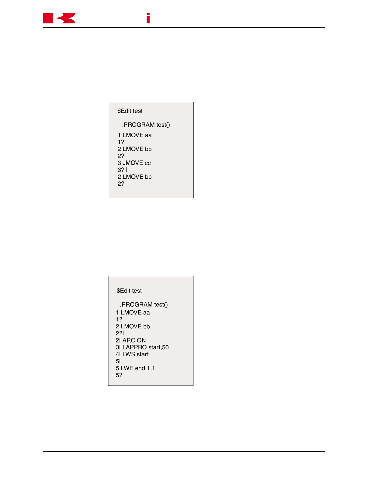
L
LAST
K
a
a
aw
k
s
AS LANGUAGE COMMANDS
Displays the previous step for editing.
C SERIES CONTROLLER
AS LANGUAGE REFERENCE MANUAL
I
INSERT
Inserts lines before the current step and all consecutive steps are
renumbered. To terminate the insert mode, press the RETURN key
twice.
November 14, 2000
4-7
Page 80

K
a
D step_count
DELETE
a
aw
k
s
AS LANGUAGE COMMANDS
Deletes program steps beginning with the current step. All consecutive steps are renumbered. The step_count specifies the
number of steps to delete beginning with the current step. If the
step count is not entered, the current step is deleted.
C SERIES CONTROLLER
AS LANGUAGE REFERENCE MANUAL
F character_string
FIND
Searches the current program for the specified character_string
from the current step to the last, and displays the first step that
includes the string.
4-8
November 14, 2000
Page 81

C SERIES CONTROLLER
K
a
M /existing_characters/new_characters
MODIFY
/existing_
characters: Characters to modify in the current step.
/new_
characters: Characters used to modify the existing characters.
a
aw
k
s
AS LANGUAGE COMMANDS
Modifies the current step by replacing the existing characters specified with the new characters specified.
AS LANGUAGE REFERENCE MANUAL
O
OVER
Places the cursor on the current step for editing.
Use the arrow keys to move the cursor within the step. The Back-
space key removes the character preceding the cursor.
November 14, 2000
4-9
Page 82

K
a
R character_string
REPLACE
character_
string: New characters to replace the existing characters.
a
aw
k
s
AS LANGUAGE COMMANDS
Replaces existing characters on current step with new characters.
To use the REPLACE command:
• Use the spacebar to move the cursor under the first character to
change.
• Press the “r” key, then the spacebar.
• Enter the new character(s) to replace existing characters in the
step and press the RETURN key.
AS LANGUAGE REFERENCE MANUAL
C SERIES CONTROLLER
4-10
November 14, 2000
Page 83

K
a
C program_name, step_number
CHANGE
a
aw
k
s
AS LANGUAGE COMMANDS
Opens the selected program for editing at the specified step
C SERIES CONTROLLER
AS LANGUAGE REFERENCE MANUAL
E
EXIT
Exits from the editor to the monitor mode.
November 14, 2000
4-11
Page 84

K
a
XD number of lines
CUT
a
aw
k
s
AS LANGUAGE COMMANDS
The XD command is used to remove (cut) a specified number of
lines from
a program and store them in the paste buffer.
Move the cursor to the first line to remove to the paste buffer and
enter XD, the number of lines to cut, and press ENTER.
The number of lines specified, including the current line, are placed
in the paste buffer and the program steps are renumbered accordingly.
When the XD command is used again, the contents of the paste
buffer are overwritten.
C SERIES CONTROLLER
AS LANGUAGE REFERENCE MANUAL
XY number of lines
COPY
The XY command is used to copy a specified number of lines from
a program and store them in the paste buffer.
Move the cursor to the first line to copy to the paste buffer and enter
XY, the number of lines to copy, and press ENTER.
The number of lines specified, including the current line, are placed
in the paste buffer.
When the XY command is used the lines in the program are not
affected.
XP
PASTE
Places the contents of the paste buffer into a program.
The steps in the paste buffer are placed in the program ahead of
the step number where the XP command is entered.
4-12
The program steps are renumbered accordingly.
November 14, 2000
Page 85

C SERIES CONTROLLER
K
a
XQ Places the contents of the paste buffer into a program in reverse
PASTE order.
XS Displays the contents of the paste buffer.
DISPLAY
a
aw
k
s
AS LANGUAGE COMMANDS
The steps in the paste buffer are placed in the program ahead of
the step number where the XQ command is entered.
The program steps are renumbered accordingly.
The XS command entered at step 2 displays the three steps in the
paste buffer.
AS LANGUAGE REFERENCE MANUAL
November 14, 2000
4-13
Page 86

K
a
4.3 PROGRAM AND DATA CONTROL COMMANDS
DIRECTORY Displays the names of all programs and variables.
DIRECTORY/P Displays the names of programs.
DIRECTORY/L Displays the names of locations.
DIRECTORY/R Displays the names of real variables.
DIRECTORY/S Displays the names of string variables.
LIST Displays all program steps and variable values.
LIST/P Displays all program steps.
a
aw
k
s
AS LANGUAGE COMMANDS
AS LANGUAGE REFERENCE MANUAL
C SERIES CONTROLLER
LIST/L Displays the value of specified locations.
LIST/R Displays the value of specified real variables.
LIST/S Displays the value of specified string variables.
DELETE Deletes specified programs and related variables.
DELETE/P Deletes specified programs.
DELETE/L Deletes specified locations.
DELETE/R Deletes specified real variables.
DELETE/S Deletes specified str ing variables.
RENAME Changes the name of a program.
XFER Copies steps from one program to another.
COPY Copies one or more programs to a new program.
4-14
November 14, 2000
Page 87

C SERIES CONTROLLER
K
a
4.3.1 DIRECTORY COMMANDS
The DIRECTORY commands display the names of programs and variables residing in
memory. If a program name is not specified when using the DIRECTORY command, all
program names, location names, real variable names, and string variable names are
listed. The screen stops at the end of each page until the spacebar is pressed, and
continues to do so until all names have been listed. Pressing the ENTER key stops the
listing.
The asterisk “*” is a wild card character which represents any character. It is used with
all program and data control commands except the RENAME command. The following
illustration shows how the asterisk is used to list specific information. For example, if
DIR w* is typed, all programs beginning with “w” and subroutine programs called by the
selected programs are listed. All locations and real variables used in the programs are
displayed.
a
aw
k
s
AS LANGUAGE COMMANDS
AS LANGUAGE REFERENCE MANUAL
November 14, 2000
4-15
Page 88
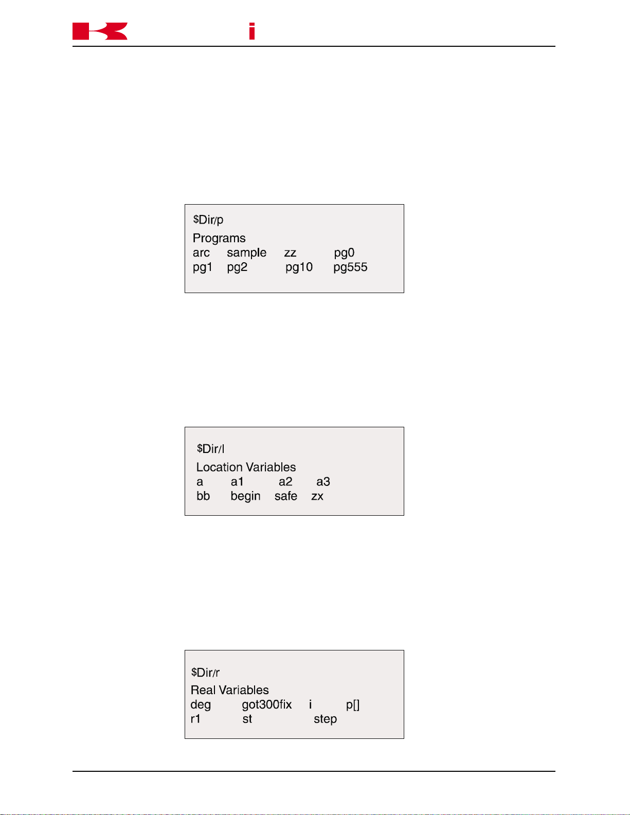
K
a
DIRECTORY/P program_name
program_name: Name of the program to be displayed.
a
aw
k
s
AS LANGUAGE COMMANDS
Displays the names of programs in memory.
C SERIES CONTROLLER
AS LANGUAGE REFERENCE MANUAL
DIRECTORY/L location_name
Displays the names of locations in memory.
location_name: Name of the location to display
DIRECTORY/R real_variable_name
Displays the names of real variables in memory.
real_variable_
name: Name of the real variable to be displayed.
4-16
November 14, 2000
Page 89

K
a
DIRECTORY/S string_variable_name
string_variable_
name: Name of the str ing variable to be displayed.
a
aw
k
s
AS LANGUAGE COMMANDS
Displays the names of string variables in memory.
AS LANGUAGE REFERENCE MANUAL
C SERIES CONTROLLER
4.3.2 LIST COMMANDS
The LIST command displays program steps and the values of variables residing in
memory. If a name is not specified when using the LIST command, all program names,
location names, real variable names, and str ing variable names are listed. The screen
stops at the end of the page until the spacebar is pressed and continues until all names
have been listed.
LIST/P program_name
Displays all program steps.
program_name: Name of the program to be listed.
November 14, 2000
4-17
Page 90
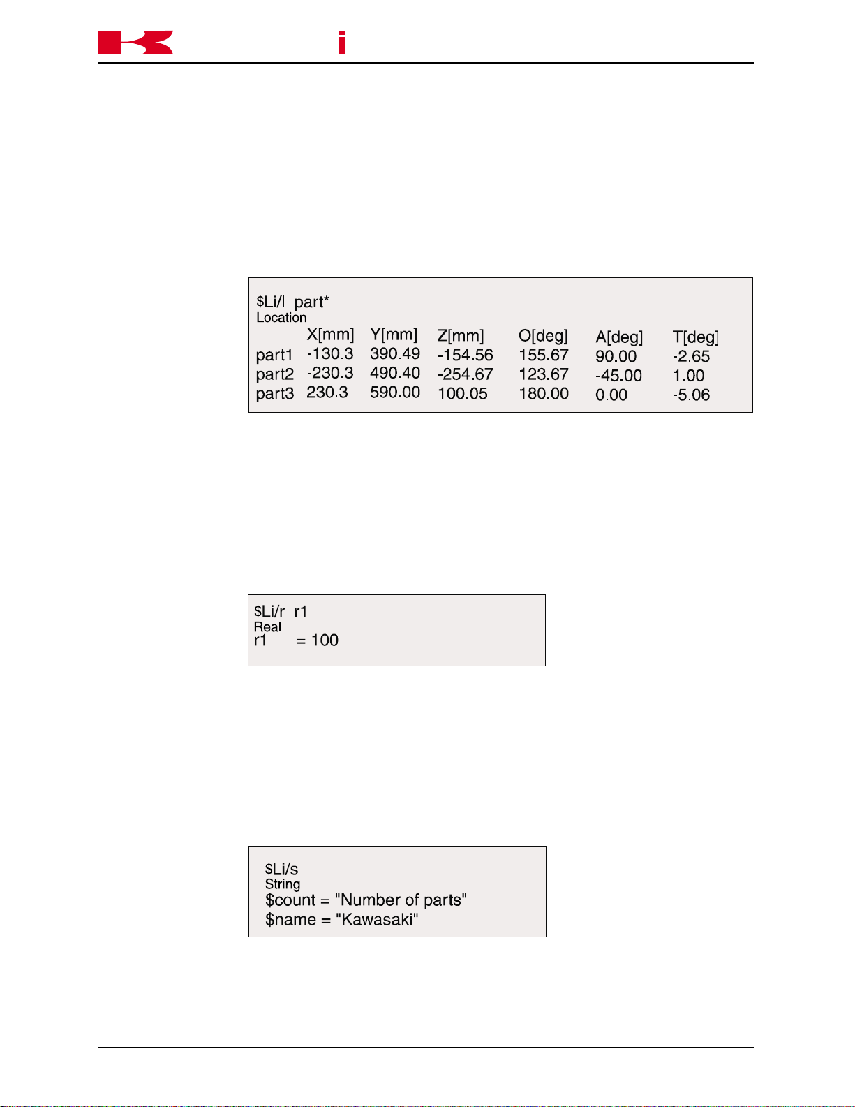
K
a
LIST/L location_name
location_name: Location variable name.
a
aw
k
s
AS LANGUAGE COMMANDS
Displays the value of the specified locations.
C SERIES CONTROLLER
AS LANGUAGE REFERENCE MANUAL
LIST/R real_variable_name
Displays the value of the specified real variable.
real_variable_
name: Real variable to be listed.
LIST/S string_variable_name
Displays the value of the specified str ing variable.
string_variable_
name: Name of str ing variable to be listed.
4-18
November 14, 2000
Page 91

C SERIES CONTROLLER
K
a
4.3.3 DELETE COMMANDS
The DELETE command is used to delete specified programs, location var iables, real
variables, and string variables from memory.
DELETE program_name
program_name: Name of program to delete. All subroutines, locations, real vari-
a
aw
k
s
AS LANGUAGE COMMANDS
Deletes the specified programs.
ables, and string variables within the specified program are deleted
unless a subroutine is called by another program. The current
program on the program stack cannot be deleted.
To delete all programs starting with a specified character, use that
character with an asterisk. If DEL s* is typed, all programs starting
with the letter “s” are deleted, including any subroutines and all
variables called by those programs. Likewise, if DEL pg* is typed,
all programs starting with “pg” are deleted, including their subroutines and variables.
AS LANGUAGE REFERENCE MANUAL
DELETE/P program_name
Deletes the specified programs.
program_name: Name of the program to delete.
November 14, 2000
4-19
Page 92
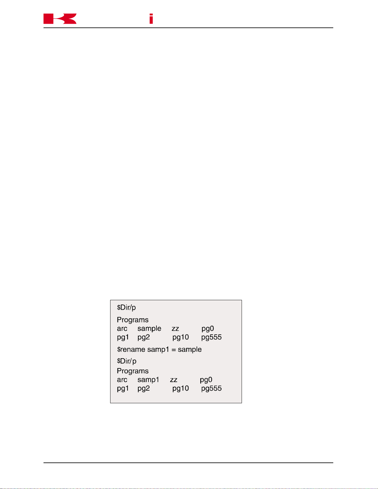
K
a
DELETE/L location_name
location_name: Name of location to delete.
DELETE/R real_variable_name
real_variable_
name: Name of real variable to delete.
DELETE/S string_variable_name
real_variable_
name: Name of the str ing variable to delete.
a
aw
k
s
AS LANGUAGE COMMANDS
Deletes the specified locations.
Deletes the specified real variables.
Deletes the specified string variables.
C SERIES CONTROLLER
AS LANGUAGE REFERENCE MANUAL
4.3.4 RENAME COMMAND
RENAME new_program_name = old_program_name
Renames the current name of a program with a new program name.
If the new program name already exists, the RENAME operation is
aborted and an error message displayed.
4-20
November 14, 2000
Page 93

C SERIES CONTROLLER
K
a
4.3.5 XFER AND COPY COMMANDS
XFER new program, start step=old program, start step, number of
new program: Name of the program to copy the specified steps into.
start step: Step to insert specified steps before.
old program: Name of the program to copy steps from.
a
aw
k
s
AS LANGUAGE COMMANDS
steps
Copies steps from one program to another (or within the same
program) and inserts them before the specified start step. The old
program steps are not replaced or deleted by this command.
AS LANGUAGE REFERENCE MANUAL
start step: Step to start coping from.
number of steps: Number of steps to copy, including the star t step.
Example: XFER pg01,2=pg02,5,4
COPY destination program name=source program name + source
program name
The copy command is used to copy a complete program or programs to a new program. The name of the destination program
cannot be an existing program.
November 14, 2000
4-21
Page 94

K
a
4.4 PROGRAM AND DATA STORAGE COMMANDS
FORMAT Initializes a PC card or a floppy disk.
FDIRECTORY Displays the name of files stored on a PC card or a disk.
SAVE Stores programs and variables in a specified file on a PC card or a
SAVE/P Stores programs in a specified file on a PC card or a disk.
SAVE/L Stores locations in a specified file on a PC card or a disk.
SAVE/R Stores real variables in a specified file on a PC card or a disk.
a
disk.
aw
k
s
AS LANGUAGE COMMANDS
AS LANGUAGE REFERENCE MANUAL
C SERIES CONTROLLER
SAVE/S Stores string variables in a specified file on a PC card or a disk.
SAVE/SYS Stores system data in a specified file on a PC card or a disk.
SAVE/ELOG Stores error log data in a specified file on a PC card or a disk.
LOAD Loads programs and variables from a specified file into system
memory.
LOAD/Q Loads selected programs and variables from a specified file into
system memory.
FDELETE Deletes specified files on a PC card or a disk.
4-22
November 14, 2000
Page 95

C SERIES CONTROLLER
K
a
4.4.1 FORMAT AND FDIRECTORY COMMANDS FORMAT Initializes a PC card or a disk to accept files. The format command
FDIRECTORY Displays names of files stored on the PC card or disk. The exten-
a
aw
k
s
AS LANGUAGE COMMANDS
erases all data on a PC card or a disk. It also sets up a directory for
keeping track of files as they are created. A new PC card or disk
must be formatted before it can be used.
sions indicate the type of file, such as system (AS), programs (PG),
auxiliary (AU), location variables (LC), real variables (RV), weld data
(WD), and string variables (ST). It also displays the size of the file,
and the date and time the file was created.
AS LANGUAGE REFERENCE MANUAL
4.4.2 SAVE COMMAND
SAVE file_name=program_name
Stores programs and variables in a specified file onto a PC card or
a disk.
file_name: Name of the file in which all programs, locations, and variables are
stored.
program_name: Name of the program stored in the specified file directory. If the
name of the program is not specified, all data in memory is stored.
If a file with the same name already exists a “B” (backup) is added
to the extension of the existing file. For example, if a file named
TEST.AS exists on disk, and a backup is made to the PC card or
disk using the same file name, the file extension is changed to
TEST.BAS and a new file TEST.AS is created.
November 14, 2000
4-23
Page 96

K
a
SAVE/P file_name=program_name
file_name: Name of the file in which programs are stored.
program_name: Name of the program to store in the specified file directory. If the
Example: SAVE/P FENDER = pg01, weld, pg02 saves programs pg01, weld,
SAVE/L file_name=program_name
a
aw
k
s
AS LANGUAGE COMMANDS
Stores programs in a specified file on a PCcard or a disk.
name of the program is not specified, all programs in memory are
stored. If the file name has no extension, PG is added.
and pg02 in the file FENDER.
AS LANGUAGE REFERENCE MANUAL
C SERIES CONTROLLER
Stores locations in a specified file on a PC card or a disk.
file_name: Name of the file in which locations are stored.
program_name: Name of the program to store in the specified file directory. If the
name of the program is not specified, all locations from memory are
stored. If the file name has no extension, LC is added.
Example: SA/L #POS saves all precision points in the file #POS.
SAVE/R file_name=program_name
Stores real variables in a specified file on a PC card or a disk.
file_name: Name of the file in which real variables are stored.
program_name: Name of the program to store in the specified file directory. If the
name of the program is not specified, all real variables from memory
are stored. If the file name has no extension, RV is added.
Example: SA/R REAL_VAR saves all real values in the file REAL_VAR.
4-24
November 14, 2000
Page 97

C SERIES CONTROLLER
K
a
SAVE/S file_name=program_name
file_name: Name of the file in which string variables are stored.
program_name: Name of the program store in the specified file directory. If the
Example: SA/S MESSAGES saves all string variables in the file MESSAGES.
SAVE/SYS file_name
a
aw
k
s
AS LANGUAGE COMMANDS
Stores character string variables in a specified file on a PC card or
a disk.
name of the program is not specified, all string variables from
memory are stored. If the file name has no extension, .ST is added.
AS LANGUAGE REFERENCE MANUAL
Stores system data in a specified file on a PC card or a disk.
file_name: Name of the file in which system data is stored with an .SY exten-
sion.
SAVE/ELOG file_name
Stores system data in a specified file on a PC card or a disk.
file_name: Name of the file in which error log data is stored with an .EL exten-
sion.
4.4.3 LOAD AND FDELETE COMMANDS
LOAD file_name
Loads programs and variables from a specified file into system
memory.
file_name: Name of file to load from disk to memory. If an extension is not
specified, .AS is assumed. All data in the specified file is loaded.
LOAD/Q file_name
Loads selected programs and variables from a specified file into
system memory. The user is prompted “Load this data? (1:Yes,
0:No, 2:Load all, 3:Exit)” before each type of data is loaded.
November 14, 2000
4-25
Page 98

K
a
file_name: Name of file to load from the PC card to memory. If an extension is
An error message is displayed if a porgram in the file selected to load already exists in
memory. If a variable is loaded from a file to memory and a variable of the same type
and same name exists the old value is lost and the new value is stored. When system
settings are loaded from a file the settings in memory are overwritten.
FDELETE file_name
file_name: Name of file to delete. When a file is deleted, its name and data are
a
aw
k
s
AS LANGUAGE COMMANDS
not specified, .AS is assumed. All selected data in the specified file
is loaded.
Deletes specified files from a PC card or a disk.
removed from the directory, and cannot be loaded from the PC card
or disk into RAM.
AS LANGUAGE REFERENCE MANUAL
C SERIES CONTROLLER
Example: FDEL pg01.pg, deletes pg01. To delete all files from the PC card or
disk enter FDEL *.*.
4.5 PROGRAM CONTROL
SPEED Sets the monitor speed.
PRIME Prepares a program for execution.
EXECUTE Executes a robot control program.
STEP Executes a single step of the program.
MSTEP Executes a single robot motion step in the program.
ABORT Stops execution after the current step is completed.
HOLD Stops execution immediately.
CONTINUE Resumes execution of the program.
STEPNEXT Executes the next program step in step once mode.
KILL Initializes the execution stack.
DO Executes a single program instruction.
4.5.1 SPEED AND PRIME COMMANDS
SPEED monitor_speed
4-26
Sets the monitor (repeat conditions) speed in percentages. The
range is from 0.01 to 100 percent. The new speed is not effective
until the next robot motion. The robot speed is determined by the
product of the monitor speed, and the program speed.
November 14, 2000
Page 99

C SERIES CONTROLLER
K
a
Example: In program pg01 shown below, the program speed is 1,000 mm/s
a
aw
k
s
AS LANGUAGE COMMANDS
and the monitor speed is 50; therefore, the robot repeat speed is
500 mm/s (50 percent of 1000 mm/s). In program pg02, the program speed for steps 1 and 3 is SP9 and steps 2 and 4 is SP6, the
monitor speed is 60; therefore, the robot repeat speed for steps 1
and 3 is 60 percent of SP9 and steps 2 and 4 is 60 percent of SP6.
AS LANGUAGE REFERENCE MANUAL
PRIME program_name, execution_cycles, step_number
program_name: The program name is optional. If omitted, the program specified by
the last EXECUTE or PRIME command is selected.
execution_cycles: Specifies the number of execution cycles. If omitted, one is as-
sumed and the program executes once. If a negative number is
entered, the program repeats continuously until 32,767 cycles are
completed.
step_numberE The optional step number allows the user to specify the program
step desired for beginning execution. If omitted, execution begins at
the first executable step.
NOTE
The PRIME command is used to prepare the system to
execute a program. The PRIME command does not execute the program.
Example: pr ime prog01,5,3 puts prog01 on the stack. When the CYCLE
START button is pushed, the command EXECUTE or CONTINUE is
typed and entered; prog01 is executed five times starting at step 3.
November 14, 2000
4-27
Page 100

K
a
4.5.2 EXECUTE, STEP, AND MSTEP COMMANDS
EXECUTE program_name, execution_cycles, step_number
program_name: Name of the program to execute. If the program name is omitted,
execution_cycles Specifies the number of execution cycles. If omitted, one is as-
step_number: Number of the step at which program execution is to begin. If
a
aw
k
s
AS LANGUAGE COMMANDS
Executes a robot control program.
the current program is executed.
sumed and the program executes once. If a negative number is
entered, the program repeats continuously until 32,767 cycles are
completed.
omitted, execution begins at the first executable step.
AS LANGUAGE REFERENCE MANUAL
C SERIES CONTROLLER
STEP program_name, repeat_count, step_number
Executes one step of the program.
program_name: Name of program to execute. If the program name is omitted, the
last executed program is selected.
repeat_count: Number of times execution of the program is repeated. If the count
is omitted, it is set to one and the user may step through all the
steps in the program only once. After the last step is executed, a
“program completed” message is displayed and the step command
becomes ineffective. To continue stepping through the program
after the last step, the user must specify a repeat_count greater
than one.
step_number: Number of the program step to be executed. If all parameters are
omitted, the next step is executed. The user can execute the de-
sired step by typing all the parameters.
Example: step pg01,1,5 executes step 5 of program pg01.
4-28
November 14, 2000
 Loading...