

Kawasaki Motorcycle Owner's Manual
Motorcycle
Owner’s Manual
ENGLISH j

Whenever you see the symbols
shown below, heed their instructions!
Always follow safe operating and maintenance practices.
NOTE
This note symbol indicates points of
○
particular interest for more efficient
and convenient operation.
WARNING
This warning symbol identifies
special instructions or proce-
dures which, if not correctly fol-
lowed, could result in personal
injury, or loss of life.
CAUTION
This caution symbol identifies
special instructions or proce-
dures which, if not strictly ob-
served, could result in damage
to or destruction of equipment.
NOTICE
THIS PRODUCT HAS BEEN
MANUFACTURED FOR USE IN A
REASONABLE AND PRUDENT
MANNER BY A QUALIFIED OPERATOR AND AS A VEHICLE
ONLY.


(Australian model only)
TAMPERING WITH NOISE CONTROL SYSTEM
PROHIBITED
Owners are warned that the law may prohibit:
a)The removal or rendering inoperative by any person other than for purposes
of maintenance, repair or replacement, of any device or element of design
incorporated into any new vehicle for the purpose of noise control prior to its
sale or delivery to the ultimate purchaser or while it is in use; and
b)the use of the vehicle after such device or element of design has been re-
moved or rendered inoperative by any person.

FOREWORD
Congratulations on your purchase of a new Kawasaki motorcycle. Your new motorcycle is the product of Kawasaki’s advanced engineering, exhaustive testing,
and co ntinuous striving for superior reliability, safety and performance.
Please read this Owner’s Manual carefully before riding so that you will be
thoroughly familiar with the proper operation of your motorcycle’s c on trols, its features, capa bilities, and lim itations. This manual offers many safe rid ing tips, but its
purpose is not to provide instruction in all the techniqu e s and skills required to ride
a motorcycle safely. Kawasaki strongly recommends that all operators of this vehicle enroll in a motorcycle rider trainin g pr og ram to attain awarene s s of the me ntal
and physical requirements necessary for safe motorcycle operation.
To ensure a long, trouble-free life for your motorcycle, give it the proper care and
maintenance described in this manual. For those who would like more detailed information on their Kawasaki Motorcycle, a Service Manual is available for purchase
from any authorized Kawasaki motorcycle dealer. The Service Manual contains detailed disassembly and maintenance information. Those who plan to do their own
work should, of course, be competent mechanics and possess the special tools
described in the Service Manual.
Keep this Owner’s Manual aboard your motorcycle at all times so that you can
refer to it whenever you need information.

This manual should be considered a permanent part of the motorcycle and should
remain with the motorcycle whe n it is sold.
All rights reserved. No part of this publication may be reproduced without our
prior written permission.
This publication includes the latest information available at the time of printing.
However, there may be minor differences between the a ctual product and illustrations and text in this manual.
All products are s ubject to change without prior notice or obligation.
KAWASAKI HEAVY INDUSTRIES, LTD.
Consumer Products & Machinery Company
© 2006 Kawasaki Heavy Industries, Ltd. Apr. 2006. (1). (M)

TABLE OF CONTENTS
SPECIFICATIONS............................... 10
LOCATION OF PARTS ....................... 14
LOADING AND ACCESSORIES
INFORMATION ................................ 17
GENERAL INFORMATION................. 20
Meter Instruments ............................ 20
Speedometer and Tachometer ..... 21
Warning/Indicator Lights ............... 21
Key................................................... 22
Ignition Switch/Steering Lock ........... 23
Right Handlebar Switches................ 24
Engine Stop Switch ...................... 24
Starter Button ............................... 25
Left Handlebar Switches .................. 26
Dimmer Switch ............................. 26
Turn Signal Switch........................ 26
Horn Button .................................. 27
Passing Button ............................. 27
Brake/Clutch Lever Adjusters........... 27
Fuel Tank Cap .................................. 28
Fuel Tank ......................................... 29
Fuel Tap ........................................... 31
Stand................................................ 33
Helmet Hook .................................... 34
Side Covers...................................... 35
Side Cover Installation .................. 35
Tool Kit ............................................. 37
Seat.................................................. 37
Seat Installation: ........................... 38
Rear Carrier ..................................... 38
BREAK-IN ........................................... 40
HOW TO RIDE THE MOTORCYCLE .42
Starting the Engine .......................... 42
Jump Starting ................................... 45
Moving Off........................................ 47
Shifting Gears .................................. 48
Braking............................................. 49
Stopping the Engine......................... 51
Stopping the Motorcycle in an
Emergency ................................... 51

Parking............................................. 52
Catalytic Converter........................... 54
SAFE OPERATION............................. 56
Safe Riding Technique ..................... 56
Daily Safety Checks ......................... 58
Additional Considerations for Off
Road Operation ............................ 60
MAINTENANCE AND ADJUSTMENT 61
Periodic Maintenance Chart............. 62
Engine Oil ........................................ 72
Cooling System ................................ 77
Spark Plugs...................................... 82
Valve Clearance ............................... 85
Air Cleaner ....................................... 86
Kawasaki Clean Air System ............. 86
Throttle Grip ..................................... 87
Choke Lever..................................... 89
Carburetors ...................................... 91
Clutch............................................... 93
Drive Chain ...................................... 95
Brakes.............................................. 102
Brake Light Switches........................ 106
Front Fork......................................... 107
Rear Shock Absorber....................... 109
Wheels ............................................. 110
Battery.............................................. 114
Headlight Beam................................ 119
Fuses ............................................... 1 21
Cleaning Your Motorcycle ................ 122
STORAGE........................................... 127
ENVIRONMENTAL PROTECTION..... 130
LOCATION OF LABELS ..................... 131

10 SPECIFICATIONS
SPECIFICATIONS
PERFORMANCE
Maximum Horsepower
Maximum Torque
Maximum Turning Radius
DIMENSIONS
Overall Length 2 215 mm (87.20 in.)
Overall Width 880 mm (34.65 in.)
Overall Height 1 270 mm (50.0 in.)
Wheelbase
Road Clearance 180 mm (7.09 in.)
Dry Weight 181 kg
ENGINE
Type
Displacement
Bore × Stroke 74.0 × 58.0 mm (2.91 × 2.28 in.)
33 kW (45 PS) @8 300 r/min (rpm)
41 N·m (4.2 kgf·m, 30.2 ft·lb) @7 500 r/min (rpm)
2.4 m (94.5 in.)
1 500 mm (59.06 in.)
DOHC, 2-cylinder, 4-stroke, liquid-cooled
498 cm³ (30.4 cu in.)

SPECIFICATIONS 11
Compression Ratio
Starting System
Cylinder Numbering
9.8 : 1
Electric starter
Left to right, 1-2
Method
Firing Order
1-2
Carburetors KEIHIN CVK34 × 2
Ignition System Battery and coil (transistorized ignition)
Ignition Timing
10° BTDC @1 300 r/min (rpm) ∼
(Electronically advanced) 35° BTDC @5 000 r/min (rpm)
Spark Plugs NGK DR9EA or ND X27ESR-U
Lubrication System Forced lubrication (wet sump)
Engine Oil
Type:
API SE, SF or SG
API SH, SJ or SL with JASO MA
SAE 10W -40
Capacity:
3.4L(3.6USqt)
Coolant Capacity 1.7 L (1.8 US qt)

12 SPECIFICATIONS
TRANSMISSION
Transmission Type
Clutch Type
Driving System Chain drive
Primary Reduction Ratio
Final Reduction Ratio
Overall Drive Ratio 5.847 (Top gear)
Gear Ratio
1st
2nd
3rd
4th
5th
6th
6-speed, constant mesh, return shift
Wet, multi disc
2.652 (61/23)
2.588 (44/17)
2.571 (36/14)
1.722 (31/18)
1.333 (28/21)
1.125 (27/24)
0.961 (25/26)
0.851 (23/27)

SPECIFICATIONS 13
FRAME
Castor 27°
Trail
105 mm (4.13 in.)
Tire Size:
Front
Rear
90/90-21 M/C 54S
130/80-17 M/C 65S
Rim Size:
Front 21 × 1.85
Rear 17 × 2.50
Fuel Tank Capacity 15.0 L (4.0 US gal)
ELECTRICAL EQUIPMENT
Battery 12 V 10 Ah
Headlight
12 V 55/55 W (Hi/Lo)
Tail/Brake Light 12 V 5/21 W
Specifications subject to change without notice, and may not apply to every country.
14 LOCATION OF PARTS
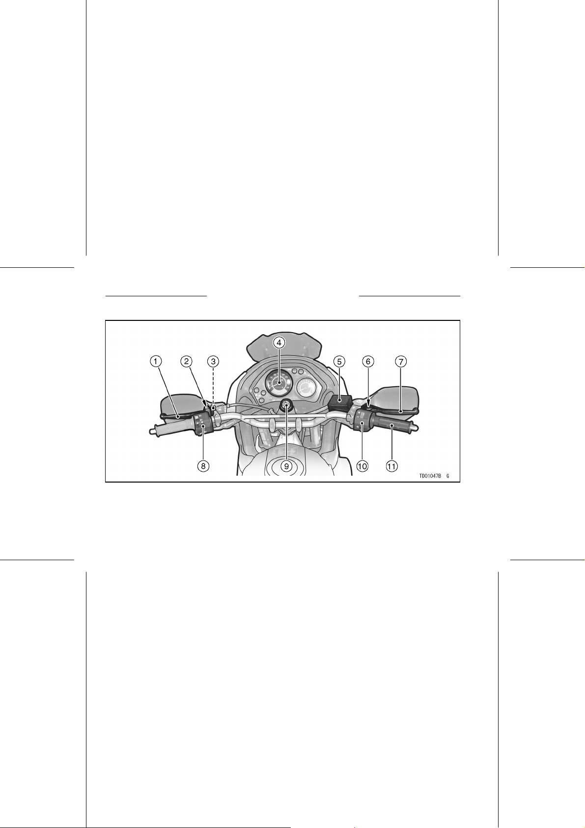
LOCATION OF PARTS
1. Clutch Lever
2. Clutch Lever Adjuster
3. Starter Lockout
Switch
4. Meter Instruments
5. Brake Fluid Reservoir
(Front)
6. Brake Lever Adjuster
7. Front Brake Lever
8. Left Handlebar
Switches
9. Ignition
Switch/Steering
Lock
10. Right Handleba r
Switches
11. Throttle Grip
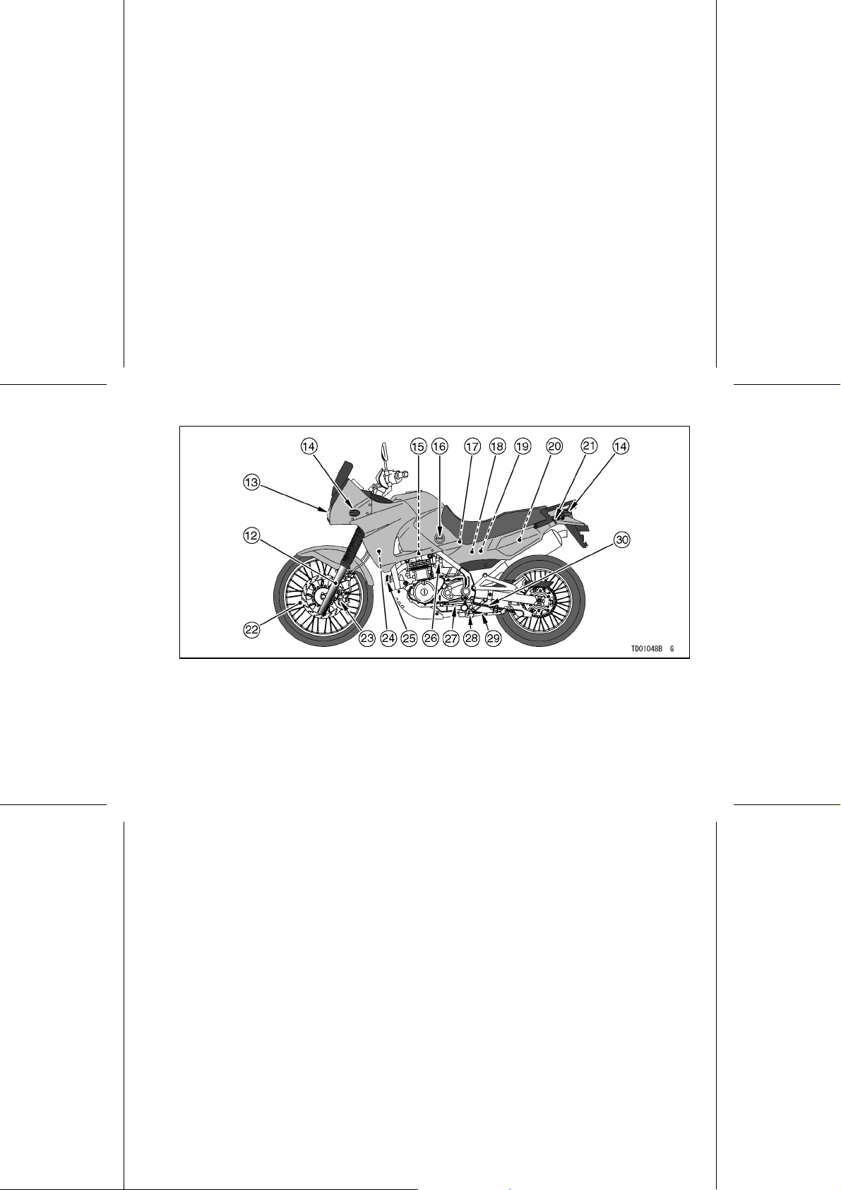
LOCATION OF PARTS 15
12. Front Fork
13. Headlight
14. Turn Signal Light
15. Spark Plugs
16. Fuel Tap
17. Air Cleaner
18. Junction Box (Fuses)
19. Battery
20. Coolant Reserve Tank
21. Helmet Hook
22. Brake Disc
23. Brake Ca liper
24. Radiator
25. Horn
26. Idle Adjusting Screw
27. Shift Pedal
28. Side Stand Switch
29. Side Stan d
30. Drive Chain
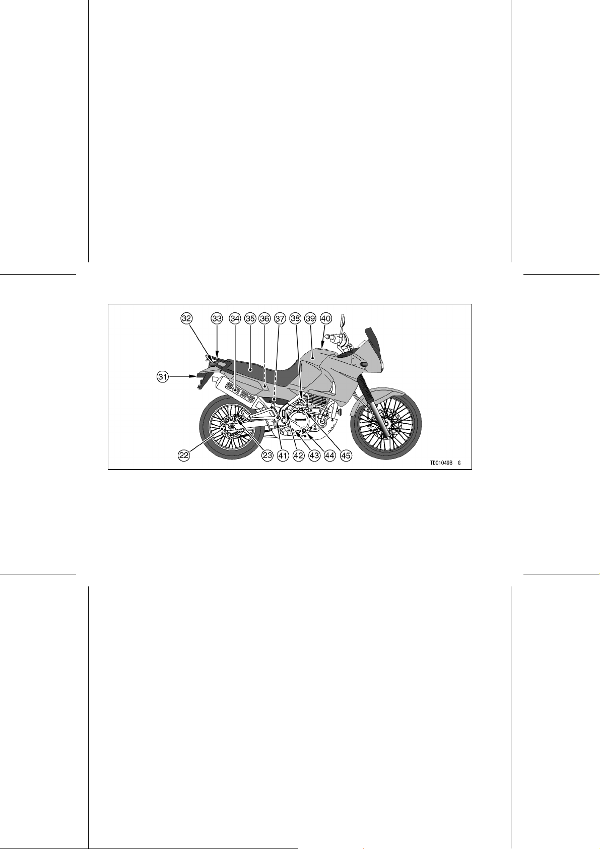
16 LOCATION OF PARTS
31. License Plate Light
32. Tail/Brake Light
33. Rear Carrier
34. Muffler
35. Seat
36. Tool Kit
37. Brake Flu id Re servoir (Rear)
38. Carburetors
39. Fuel Tank
40. Fuel Tank Cap
41. Rear Shock Absorber
42. Rear Brake Light Switch
43. Rear Brake Pedal
44. Oil Level Gauge
45. Oil Filler
LOADING AND ACCESSORIES INFORMATION 17
LOADING AND ACCESSORIES INFORMATION
WARNING
Incorrect loading, improper installation or use of accessories,
or modification of your motorcycle may result in an unsafe riding condition. Before you ride
the motorcycle, make sure that
the motorcycle is not overloaded
and that you have followed these
instructions.
With the exception of genuine
Kawasaki Parts and Accessories,
Kawasaki has no control over the
design or application of accessories.
In some cases, improper installation
or use of accessories, or motorcycle
modification, will void the motorcycle
warranty can negatively affect performance, and can even be illegal. In
selecting and using accessories, and
in loading the motorcycle, you are
personally responsible for your own
safety and the safety of other persons
involved.
NOTE
Kawasaki Parts and Accessories
○
have been specially designed for
use on Kawasaki motorcycles. We
strongly recommend that all parts
and accessories you add to your
motorcycle be genuine Kawasaki
components.
Because a motorcycle is sensitive t o
changes in weight and aerodynamic
forces, you must take extreme care

18 LOADING AND ACCESSORIES INFORMATION
in carrying cargo, passengers and/or
in the fitting of additional accessories.
The following general guidelines have
been prepared to assist you in making
your determinations.
1. Any passenger should be thoroughly familiar with motorcycle operation. The passenger can affect
control of the motorcycle by improper positioning during cornering
and sudden movements. It is important that the passenger sit still while
the motorcycle is in motion and not
interfere with the operation of the
motorcycle. Do not carry animals
on your motorcycle.
2. You should instruct any passenger
before riding to keep his feet on the
passenger footpegs and hold on to
the operator, se at strap or gr ab rail.
Do not carry a passenger unless he
or she is tall enough to reach the
footpegs and footpegs are provided.
3. All baggage should be carried as
low as possible to reduce the effect
on the motorcycle center of gravity.
Baggage weight should also be distributed equally on both sides of the
motorcycle. Avoid carrying baggage
that extends beyond the rear of the
motorcycle.
4. Baggage should be securely attached. Make sure that the baggage
will not move around while you are
riding. Recheck baggage security
as often as possible (not while the
motorcycle is in motion) and adjust
as necessary.
5. Do not carry heavy or bulky items on
a luggage rack. They are designed
for light items, and overloading can
affect handling due to changes in
weight distribution and aerodynamic
forces.

LOADING AND ACCESSORIES INFORMATION 19
6. Do not install accessories or carry
baggage that impairs the performance of the motorcycle. Make
sure that you have not adversely
affected any lighting components,
road clearance, banking capability
(i.e., lean angle), control operation,
wheel travel, front fork movement,
or any other aspect of the motorcycle’s operation.
7. Weight attached to the handlebar or
front fork will increa se the mass of
thesteeringassemblyandcanresult in an unsafe riding condition.
8. Fairings, windshields, backrests,
and other large items have the capability of adversely affecting stability and handling of the motorcycle,
not only because of their weight, but
also due to the aerodynamic forces
acting on these surfaces while the
motorcycle is in operation. Poorly
designed or installed items can result in an unsafe riding condition.
9. This motorcycle was not intended
to be equipped with a sidecar or to
be used to tow any trailer or other
vehicle. Kawasaki does not manufacture sidecars or trailers for motorcycles and cannot predict the effects of such accessories on handling or stability, but can only warn
thattheeffectscanbeadverseand
that Kawasaki cannot assume responsibility for the results of such
unintended use of the motorcycle.
Furthermore, any adverse effects on
motorcycle components caused by
the use of such accessories will not
be remedied under w arranty.
Maximum Load
Weight of rider, passenger, b aggage,
and accessories must not exceed 180 kg
(397 lb).
20 GENERAL INFORMATION
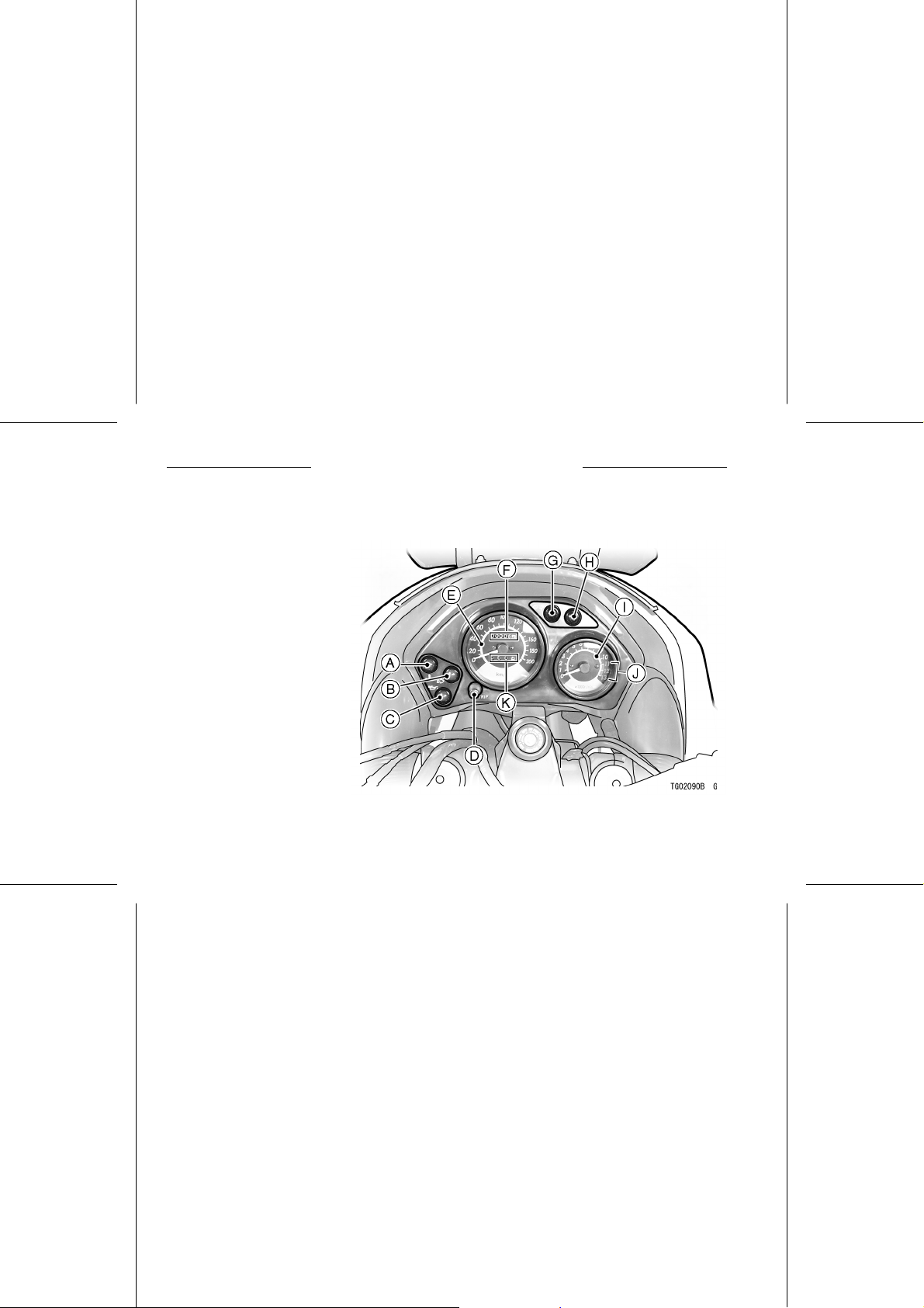
Meter Instruments
A. Coolant Temperature
Warning Light
B. High Beam Indicator Light
C. Oil Pressure Warning Light
D. Reset Button
E. Speedometer
F. Odometer
G. Turn Sign al Indicator Light
H. Neutral Indicator Light
I. Tachometer
J. Red Zone
K. Trip Meter
GENERAL INFORMATION
GENERAL INFORMATION 21
Speedometer and Tachometer
The speedometer shows the speed
of the vehicle. In the speedometer
face are the odometer and trip meter.
The odometer shows the total distance
that the vehicle has been ridden. The
trip meter sho ws the distanc e traveled
since it was last reset to zero. The trip
meter can be reset to zero by pushing
the reset button.
The tachometer shows the engine
speed in the revolutions per minute
(r/min, rpm). On the right side of the
tachometer face is a portion called
the “red zone.” Engine r/min (rpm) in
the red zone is above maximum recommended engine speed and is also
above the range for good performance.
CAUTION
Engine r/min (rpm) should not
be allowed to enter the red zone;
operation in the red zone will
overstress the engine and may
cause serious engine damage.
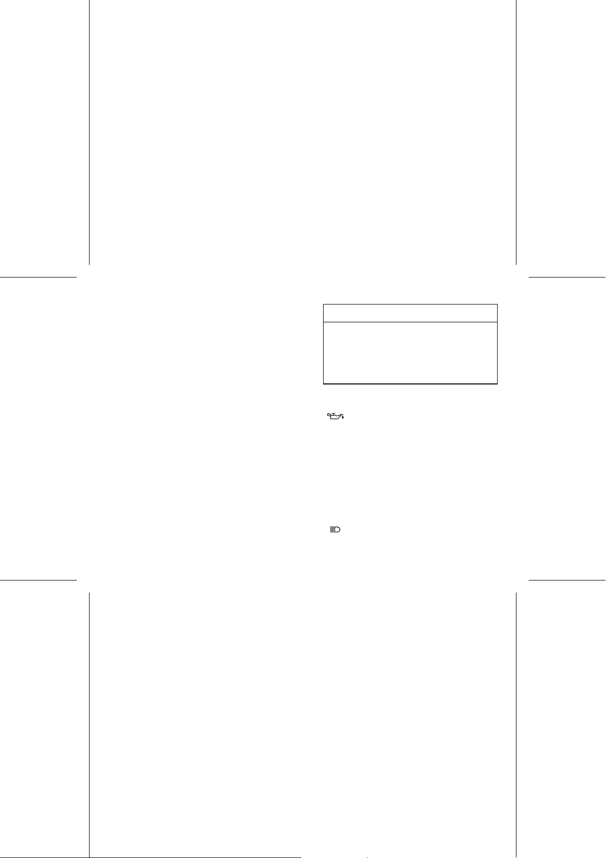
Warning/Indicator Lights
: The oil pressure warning light
goes on whenever the oil pressure is
dangerously low or the ignition key is
in the ON position with the engine not
running, and goes off when the engine
oil pressure is high enough. Refer to
the Maintenance and Adjustment chapter for more detailed engine oil information.
: When the headlight is on high
beam, the high beam indicator light is
lit.

22 GENERAL INFORMATION
: When the turn signal switch is
turned to left or right, the turn signal
indicator light flashes on and off.
N : When the transmission is in neutral,
the neutral indicator light is lit.
The coolant temperature warning
light goes on when the ignition switch
is turned on and goes off soon after the
engine starts running to ensure that its
circuit functions properly. The warning
light also goes on whenever the coolant
temperature rises to 120°C or higher
when the motorcycle is in operation. If it
stays on, stop the engine and check the
coolant level in the reserve tank after
the engine cools down.
Key
This motorcycle has a combination
key,whichisusedfortheignition
switch/steering lock, helmet hook, right
side cover, and fuel tank cap.
Blank keys are available at your
Kawasaki dealers. Ask your dealer to
make any additional spare keys you
may need, using your original key as a
master.
GENERAL INFORMATION 23
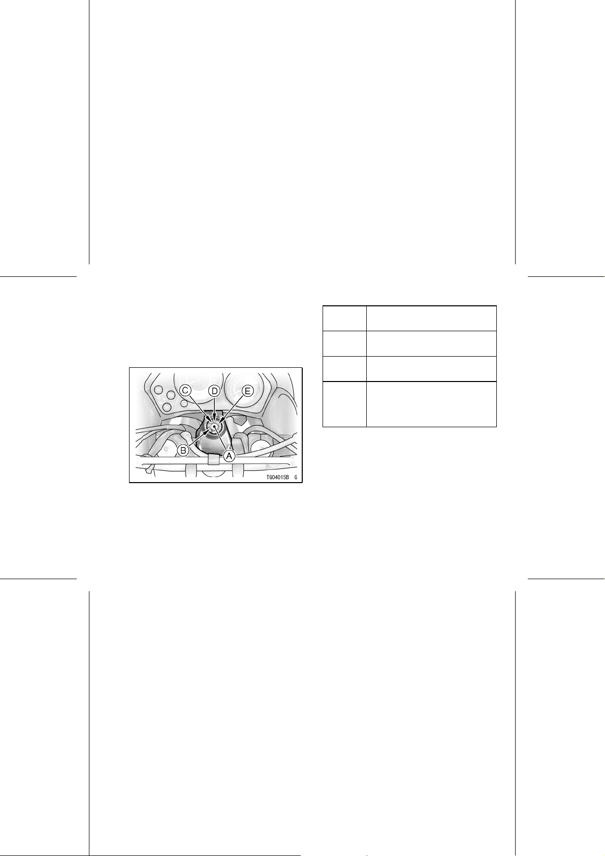
Ignition Switch/Steering Lock
This is a four-position, key-operated
switch. The key can be removed from
the switch when it is in the OFF, LOCK,
or P (Park) position.
A. Ignition Switch/Steering Lock
B. LOCK position
C. OFF position
D. ON position
E. P (Park) position
OFF
ON
LOCK
P(Park)
Engine off. All electrical
circuits off.
Engine on. All electrical
equipment can be used.
Steering locked. Engine off.
All electrical circuits off.
Steering locked. Engine off.
Tail and city (except Australian
model) lights on. All ot her
electrical circuits cut off.
NOTE
The tail and city lights (Except for
○
Australia model) are on whenever
theignitionswitchisintheONposition. The headlight goes on when
the starter button is released after
starting the engine. To avoid battery
discharge, always start the engine
immediately after turning the ignition
switch to “ON”.
24 GENERAL INFORMATION
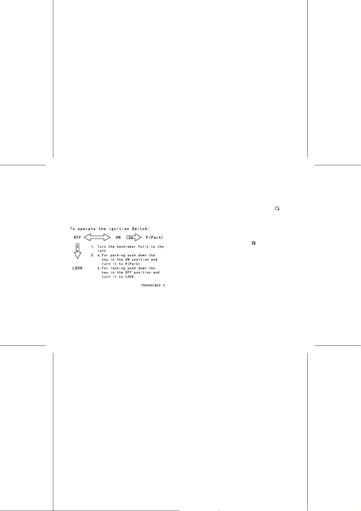
If you leave the P (park) position on
○
for a long time (one hour), the battery
may become totally discharged.
To operate the ignition switch;
Right Handlebar Switches
Engine Stop Switch
In addition to the ignition switch, the
enginestopswitchmustbeinthe
position for the motorcycle to operate.
Theenginestopswitchisforemergency use. If some emergency requires stopping the engine, move the
enginestopswitchtothe
position.
NOTE
Although the engine stop switch
○
stops the engine, it does not turn off
all the electrical circuits. Ordinarily,
theignitionswitchshouldbeusedto
stop the engine.
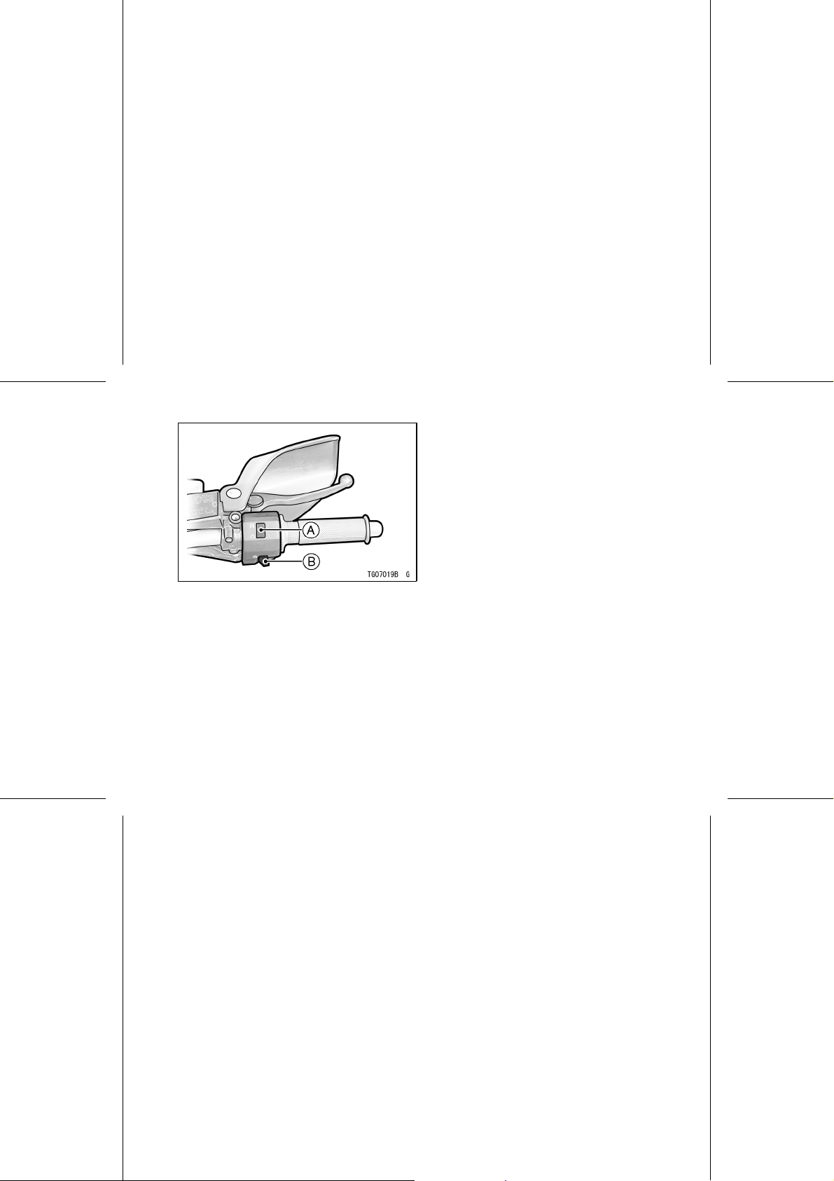
A. Engine Stop Switch
B. Starter Button
Starter Button
The starter button operates the electric starter when pushed with the clutch
lever pulled in or the transmission in
neutral.
GENERAL INFORMATION 25
Refer to the Starting the Engine sectionofthe"HowtoRidetheMotorcycle"
chapter for starting instructions.
26 GENERAL INFORMATION
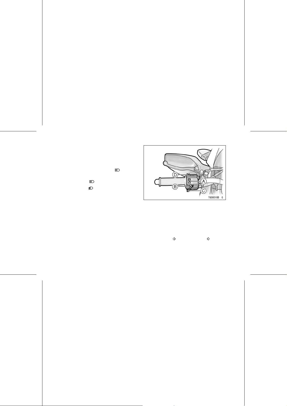
Left Handlebar Switches
Dimmer Switch
High or low beam can be selected
with the dimmer switch. When the
headlight is on high beam (
), the
high beam indicator light is lit.
High beam.......(
Low beam.......(
)
)
NOTE
High a nd low beam do not go on at
○
thesametime. Onegoesoffwhen
the other is lit.
A. Dimmer Switch
B. Turn Signal Switch
C. Horn Button
D. Passing Button
Turn Signal Switch
When the turn signal switch is tu r ned
to the left (
)orright( ), the
turn signals flash on and off.
To stop flashing, push the switch in.

GENERAL INFORMATION 27
Horn Button
When the horn button is pushed, the
horn sounds.
Passing Button
When the passing button is pushed,
the headlight high beam (passing
beam) comes on to signal the driver of
the vehicle ahead that you are about to
pass him. The passing light shuts off
as so on as the switch is released.
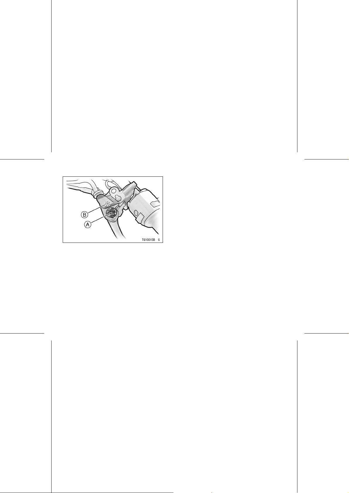
Brake/Clutch Lever Adjusters
There is an adjuster on both the
brake and clutch levers. The brake
lever adjuster has 4 positions and the
clutch lever adjuster has 5 positions so
that the released lever position can be
adjusted to suit the operator’s hands.
Push the lever forward and turn the
adjuster to align the number with the
triangular mark on the lever holder.
Thedistanceformthegriptothereleased lever is minimu m at Number
4 for the brake lever and Number 5
for the clutch lever, and maximum at
Number 1 for both.
28 GENERAL INFORMATION
A. Adjuster
B. Mark
Fuel Tank Cap
To open the fuel tank cap, pull up
the key hole cover. Insert the ign ition
switch key into the lock and turn the key
to the right.
To close the cap, push it down into
place with the key ins erted. The key
can be removed by turning it counterclockwise to the original position.
NOTE
The tank cap cannot be closed with-
○
out the key inserte d, and the key cannot be removed unless the cap is
locked properly.
Do not push on the key to close the
○
cap, or the cap cannot be locked.
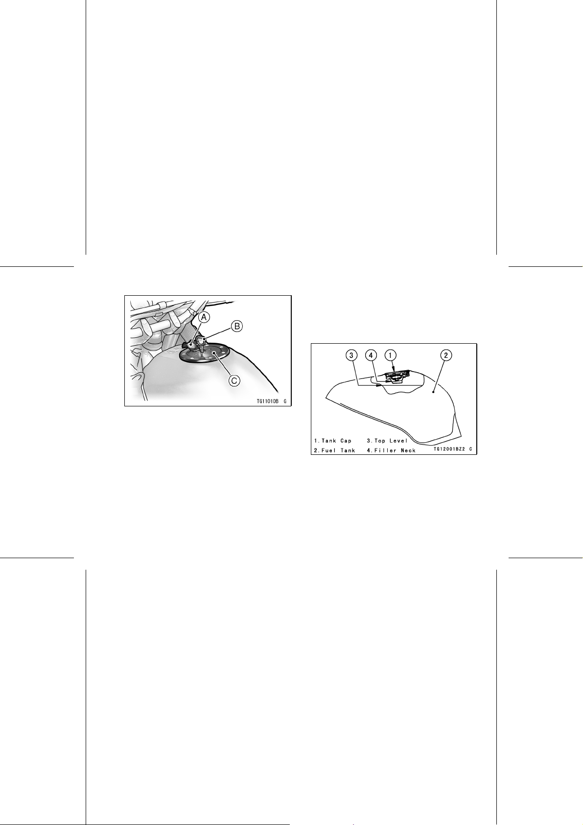
A.KeyHoleCover
B. Ignition Switch Key
C. Fuel Tank Cap
GENERAL INFORMATION 29
Fuel Tank
Avoid filling the tank in the rain or
where heavy dust is blowing so that the
fuel does not get contaminated.
30 GENERAL INFORMATION
WARNING
Gasoline is extremely flammable
and can be explosive under certain conditions. Turn the ignition
key to “OFF.”
Do not smoke. Make sure the
area is well ventilated and free
from any source of flame or
sparks; this includes any appliance with a pilot light.
Never fill the tank so the fuel
level rises into the filler neck. If
the tank is overfilled, heat may
cause the fuel to expand and
overflow through the vents in
the tank cap.
After refueling, make sure the
tank cap is closed securely.
If gasoline is spilled on the fuel
tank, wipe it off immediately.
Fuel Requirement:
Your Kawasaki engine is designed to
use only unleaded gasoline.
CAUTION
Do not use leaded gasoline, as
this will destroy the catalytic
converter. (For further information, refer to the “Catalytic
Converter” section in the “How
to Rider the Motorcycle” chapter).
Octane Rating
Theoctaneratingofagasolineisa
measure of its resistance to detonation or "knocking." The term commonly
used to describe a gasoline’s octane
rating is the Research Octane Number
(RON). Always use a gasoline with an
octane rating equal to, or higher than,
Research Octane Number (RON) 91.
 Loading...