

Kawasaki KLF250-A1 KLF250-A2 2004, KLF250-A3 2005, KLF250A6F 2006, KLF 250, BAYOU 250 Service Manual
...
KLF 250
BAYOU 250
Workhorse 250
All Terrain Vehicle
Service Manual


Quick Reference Guide
General Information 1 j
Periodic Maintenance 2 j
Fuel System 3 j
Engine Top End 4 j
Engine Right Side 5 j
Recoil Starter 6 j
Engine Lubrication System 7 j
Engine Removal/Installation 8 j
This quick reference guide will assist
you in locating a desired topic or procedure.
•Bend the pages back to match the
black tab of the desired chapter number with the black tab on the edge at
each table of contents page.
•Refer to the sectional table of contents
for the exact pages to locate the specific topic required.
Crankshaft/Transmission 9 j
Wheels/Tires 10 j
Final Drive 11 j
Brakes 12 j
Suspension 13 j
Steering 14 j
Frame 15 j
Electrical System 16 j
Appendix 17 j


KLF 250
BAYOU 250
Workhorse 250
All Terrain Vehicle
Service Manual
All rights reserved. No parts of this publication may be reproduced, stored in a retrieval system, or
transmitted in any form or by any means, electronic mechanical photocopying, recording or otherwise,
without the prior written permission of Quality Division/Consumer Products & Machinery Company/Kawasaki
Heavy Industries, Ltd., Japan.
No liability can be accepted for any inaccuracies or omissions in this publication, although every possible
care has been taken to make it as complete and accurate as possible.
The right is reserved to make changes at any time without prior notice and without incurring an obligation
to make such changes to products manufactured previously. See your dealer for the latest information on
product improvements incorporated after this publication.
All information contained in this publication is based on the latest product information available at the time
of publication. Illustrations and photographs in this publication are intended for reference use only and may
not depict actual model component parts.
© 2002 Kawasaki Heavy Industries, Ltd. Forth Edition (1) :Apr. 1, 2005 (K)

LIST OF ABBREVIATIONS
A ampere(s) lb pounds(s)
ABDC after bottom dead center m meter(s)
AC alternating current min minute(s)
ATDC after top dead center N newton(s)
BBDC before bottom dead center Pa pascal(s)
BDC bottom dead center PS horsepower
BTDC before top dead center psi pound(s) per square inch
°C degree(s) Celcius r revolution
DC direct current rpm revolution(s) per minute
F farad(s) TDC top dead center
°F degree(s) Fahrenheit TIR total indicator reading
ft foot, feet V volt(s)
g gram(s) W watt(s)
h hour(s) Ω ohm(s)
L liter(s)
Read OWNER’S MANUAL before operating.

EMISSION CONTROL INFORMATION
To protect the environment in which we all live, Kawasaki has incorporated crankcase emission
(1) and exhaust emission (2) control systems in compliance with applicable regulations of the
California Air Resources Board.
1. Crankcase Emission Control System
A sealed-type crankcase emission control system is used to eliminate blow-by gases. The blow
-by gases are led to the breather chamber through the crankcase. Then, it is led to the air cleaner.
Oil is separated from the gases while passing through the inside of the breather chamber from
the crankcase, and then returned back to the bottom of crankcase.
2. Exhaust Emission Control System
The exhaust emission control system applied to this engine family is engine modifications that
consist of a modified carburetor and an ignition system having optimum ignition timing characteristics.
The carburetor has been calibrated to provide lean air/fuel mixture characteristics and optimum
fuel economy with a suitable air cleaner and exhaust system.
A maintenance free ignition system provides the most favorable ignition timing and helps main-
tain a thorough combustion process within the engine which contributes to a reduction of exhaust
pollutants entering the atomosphere.
The Clean Air Act, which is the Federal law covering motor vehicle pollution, contains what is
commonly referred to as the Act’s "tampering provisions."
"Sec. 203(a) The following acts and the causing thereof are prohibited...
(3)(A) for any person to remove or render inoperative any device or element of design installed
on or in a motor vehicle or motor vehicle engine in compliance with regulations under this
title prior to its sale and delivery to the ultimate purchaser, or for any manufacturer or dealer
knowingly to remove or render inoperative any such device or element of design after such
sale and delivery to the ultimate purchaser.
(3)(B) for any person engaged in the business of repairing, servicing, selling, leasing, or trading
motor vehicles or motor vehicle engines, or who operates a fleet of motor vehicles knowingly to remove or render inoperative any device or element of design installed on or in a
motor vehicle or motor vehicle engine in compliance with regulations under this title following its sale and delivery to the ultimate purchaser..."
NOTE
The phrase "remove or render inoperative any device or element of design" has been generally
○
interpreted as follows:
1. Tampering does not include the temporary removal or rendering inoperative of devices or elements of design in order to perform maintenance.
2. Tampering could include:
a.Maladjustment of vehicle components such that the emission standards are ex-
ceeded.
b.Use of replacement p arts or accessories which adversely affect the performance
or durability of the motorcycle.
c.Addition of components or accessories that result in the vehicle exceeding the stan-
dards.
d.Permanently removing, disconnecting, or rendering inoperative any component or
element of design of the emission control systems.
WE RECOMMEND THAT ALL DEALERS OBSERVE THESE PROVISIONS OF FEDERAL LAW,
THE VIOLATION OF WHICH IS PUNISHABLE BY CIVIL PENALTIES NOT EXCEEDING
$10,000 PER VIOLATION.

PLEASE DO NOT TAMPER WITH NOISE CONTROL SYSTEM
(US MODEL only)
To minimize the noise emissions from this product, Kawasaki has equipped it with effective
intake and exhaust silencing systems. They are designed to give optimum performance while
maintaining a low noise level. Please do not remove these systems, or alter them in any which
results in an increase in noise level.
Foreword
This manual is designed primarily for use by
trained mechanics in a properly equipped shop.
However, it contains enough detail and basic information to make it useful to the owner who desires to perform his own basic maintenance and
repair work. A basic knowledge of mechanics,
the proper use of tools, and workshop procedures must be understood in order to carry out
maintenance and repair satisfactorily. Whenever the owner has insufficient experience or
doubts his ability to do the work, all adjustments, maintenance, and repair should be carried out only by qualified mechanics.
In order to perform the work efficiently and
to avoid costly mistakes, read the text, thoroughly familiarize yourself with the procedures
before starting work, and then do the work carefully in a clean area. Whenever special tools or
equipment are specified, do not use makeshift
tools or equipment. Precision measurements
can only be made if the proper instruments are
used, and the use of substitute tools may adversely affect safe operation.
For the duration of the warranty period,
we recommend that all repairs and scheduled
maintenance be performed in accordance with
this service manual. Any owner maintenance or
repair procedure not performed in accordance
with this manual may void the warranty.
To get the longest life out of your vehicle:
Follow the Periodic Maintenance Chart in the
•
Service Manual.
Be alert for problems and non-scheduled
•
maintenance.
Use proper tools and genuine Kawasaki Vehi-
•
cle parts. Special tools, gauges, and testers
that are necessary when servicing Kawasaki
vehicles are introduced by the Service Man-
ual. Genuine parts provided as spare parts
are listed in the Parts Catalog.
Follow the procedures in this manual care-
•
fully. Don’t take shortcuts.
Remember to keep complete records of main-
•
tenance and repair with dates and any new
parts installed.
How to Use This Manual
In this manual, the product is divided into
its major systems and these systems make up
the manual’s chapters. The Quick Reference
Guide shows you all of the product’s system
and assists in locating their chapters. Each
chapter in turn has its own comprehensive Table of Contents.
For example, if you want ignition coil information, use the Quick Reference Guide to locate
the Electrical System chapter. Then, use the
Table of Contents on the first page of the chapter to find the Ignition Coil section.
Whenever you see these WARNING and
CAUTION symbols, heed their instructions!
Always follow safe operating and maintenance
practices.
WARNING
This warning symbol identifies special
instructions or procedures which, if not
correctly followed, could result in per-
sonal injury, or loss of life.
CAUTION
This caution symbol identifies special
instructions or procedures which, if not
strictly observed, could result in dam-
age to or destruction of equipment.
This manual contains four more symbols (in
addition to WARNING and CAUTION) which will
help you distinguish different types of information.
NOTE
This note symbol indicates points of par-
○
ticular interest for more efficient and con-
venient operation.
Indicates a procedural step or work to be
•
done.
Indicates a procedural sub-step or how to do
○
the work of the procedural step it follows. It
also precedes the text of a NOTE.
Indicates a conditional step or what action to
take based on the results of the test or inspec-
tion in the procedural step or sub-step it fol-
lows.
In most chapters an exploded view illustration
of the system components follows the Table of
Contents. In these illustrations you will find the
instructions indicating which parts require specified tightening torque, oil, grease or a locking
agent during assembly.


GENERAL INFORMATION 1-1
General Information
Table of Contents
Before Servicing ..................................................................................................................... 1-2
Model Identification................................................................................................................. 1-5
General Specifications............................................................................................................ 1-6
Unit Conversion Table ............................................................................................................ 1-9
1

1-2 GENERAL INFORMATION
Before Servicing
Before starting to perform an inspection service or carry out a disassembly and reassembly operation on a motorcycle, read the precautions given below. To facilitate actual operations, notes, illustrations, photographs, cautions, and detailed descriptions have been included in each chapter wherever
necessary. This section explains the items that require particular attention during the removal and
reinstallation or disassembly and reassembly of general parts.
Especially note the following:
(1) Dirt
Before removal and disassembly, clean the motorcycle. Any dirt entering the engine will shorten
the life of the motorcycle. For the same reason, before installing a new part, clean off any dust or
metal filings.
(2) Battery Ground
Disconnect the ground (−) wire from the battery before performing any disassembly operations
on the vehicle. This prevents the engine from accidentally turning over while work is being carried
out, sparks from being generated while disconnecting the wires from electrical parts, as well as
damage to the electrical parts themselves. For reinstallation, first connect the positive wire to the
positive (+) terminal of the battery
(3) Installation, Assembly
Generally, installation or assembly is the reverse of removal or disassembly. However, if installation or assembly sequence is given in this Service Manual, follow it. Note parts locations and
cable, wire, and hose routing during removal or disassembly so they can be installed or assembled in the same way. It is preferable to mark and record the locations and routing whenever
possible.
(4) Tightening Sequence
When installing bolts, nuts, or screws for which a tightening sequence is given in this Service
Manual, make sure to follow the sequence. When installing a part with several bolts, nuts, or
screws, start them all in their holes and tighten them to a snug fit, thus ensuring that the part has
been installed in its proper location. Then, tighten them to the specified torque in the tightening
sequence and method indicated. If tightening sequence instructions are not given, tighten them
evenly in a cross pattern. Conversely, to remove a pat, first loosen all the bolts, nuts, or screws
that are retaining the part a 1/4-turn before removing them.
(5) Torque
When torque values are given in this Service Manual, use them. Either too little or too much
torque may lead to serious damage. Use a good quality, reliable torque wrench.
(6) Force
Common sense should dictate how much force is necessary in assembly and disassembly. If
a part seems especially difficult to remove or install, stop and examine what may be causing the
problem. Whenever tapping is necessary, tap lightly using a wooden or plastic-faced mallet. Use
an impact driver for screws (particularly for the removing screws held by non-permanent locking
agent) in order to avoid damaging the screw heads.
(7) Edges
Watch for sharp edges, as they could cause injury through careless handling, especially during
major engine disassembly and assembly. Use a clean piece of thick cloth when lifting the engine
or turning it over.
(8) High-Flash Point Solvent
A high-flash point solvent is recommended to reduce fire danger. A commercial solvent commonly available in North America is standard solvent (generic name). Always follow manufacturer
and container directions regarding the use of any solvent.
(9) Gasket, O-ring
Replace a gasket or an O-ring with a new part when disassembling. Remove any foreign matter
from the mating surface of the gasket or O-ring to ensure a perfectly smooth surface to prevent
oil or compression leaks.

GENERAL INFORMATION 1-3
Before Servicing
(10)Liquid Gasket, Locking Agent
Clean and prepare surfaces where liquid gasket or non-permanent locking agent will be used.
Apply them sparingly. Excessive amount may block engine oil passages and cause serious damage.
(11)Press
When using a press or driver to install a part such as a wheel bearing, apply a small amount of
oil to the area where the two parts come in contact to ensure a smooth fit.
(12)Ball Bearing and Needle Bearing
Do not remove a ball bearing or a needle bearing unless it is absolutely necessary. Replace any
ball or needle bearings that were removed with new ones. Install bearings with the manufacturer
and size marks facing out, applying pressure evenly with a suitable driver. Apply force only to the
end of the race that contacts the press fit portion, and press it evenly over the base component.
(13)Oil Seal and Grease Seal
Replace any oil or grease seals that were removed with new ones, as removal generally damages seals. Oil or grease seals should be pressed into place using a suitable driver, applying a
force uniformly to the end of seal until the face of the seal is even with the end of the hole, unless
instructed otherwise. When pressing in an oil or grease seal which has manufacturer’s marks,
press it in with the marks facing out.
(14)Circlip, Retaining Ring, and Cotter Pin
When installing circlips and retaining rings, take care to compress or expand them only enough
to install them and no more. Install the circlip with its chamfered side facing load side as well.
Replace any circlips, retaining rings, and cotter pins that were removed with new ones, as removal weakens and deforms them. If old ones are reused, they could become detached while
the motorcycle is driven, leading to a major problem.
(15)Lubrication
Engine wear is generally at its maximum while the engine is warming up and before all the sliding
surfaces have an adequate lubricative film. During assembly, make sure to apply oil to any sliding
surface or bearing that has been cleaned. Old grease or dirty oil could have lost its lubricative
quality and may contain foreign particles that act as abrasives; therefore, make sure to wipe it off
and apply fresh grease or oil. Some oils and greases in particular should be used only in certain
applications and may be harmful if used in an application for which they are not intended.
(16)Direction of Engine Rotation
To rotate the crankshaft manually, make sure to do so in the direction of positive rotation. Positive rotation is counterclockwise as viewed from the left side of the engine. To carry out proper
adjustment, it is furthermore necessary to rotate the engine in the direction of positive rotation as
well.
(17)Replacement Parts
When there is a replacement instruction, replace these parts with new ones every time they are
removed.
Replacement parts will be damaged or lose their original function once they are removed. Therefore, always replace these parts with new ones every time they are removed. Although the previously mentioned gasket, O-ring, ball bearing, needle bearing, grease seal, oil seal, circlip, and
cotter pin have not been so designated in their respective text, they are replacement parts.
(18)Electrical Wires
All the electrical wires are either one-color or two-color. A two-color wire is identified first by the
primary color and then the stripe color. For example, a yellow wire with thin red stripes is referred
to as a “yellow/red” wire; it would be a “red/yellow” wire if the colors were reversed. Unless instructed otherwise, electrical wires must be connected to wires of the same color.

1-4 GENERAL INFORMATION
Before Servicing
Two-Color Electrical Wire
(19)Inspection
When parts have been disassembled, visually inspect these parts for the following conditions
or other damage. If there is any doubt as to the condition of them, replace them with new ones.
Abrasion Crack Hardening Warp
Bent Dent
Color change Deterioration Seizure
(20)Specifications
Specification terms are defined as follows:
"Standards" s how dimensions or performances which brand-new parts or systems have.
"Service Limits" indicate the usable limits. If the measurement shows excessive wear or dete-
riorated performance, replace the damaged parts.
Scratch
Wear
Model Identification
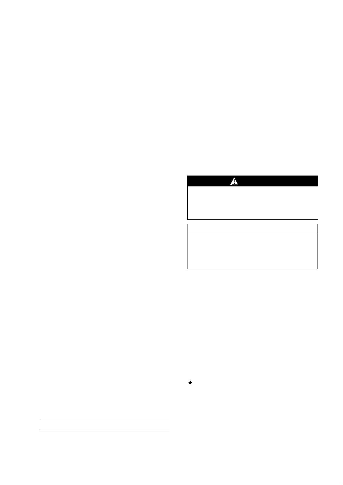
KLF250-A1 Left Side View
GENERAL INFORMATION 1-5
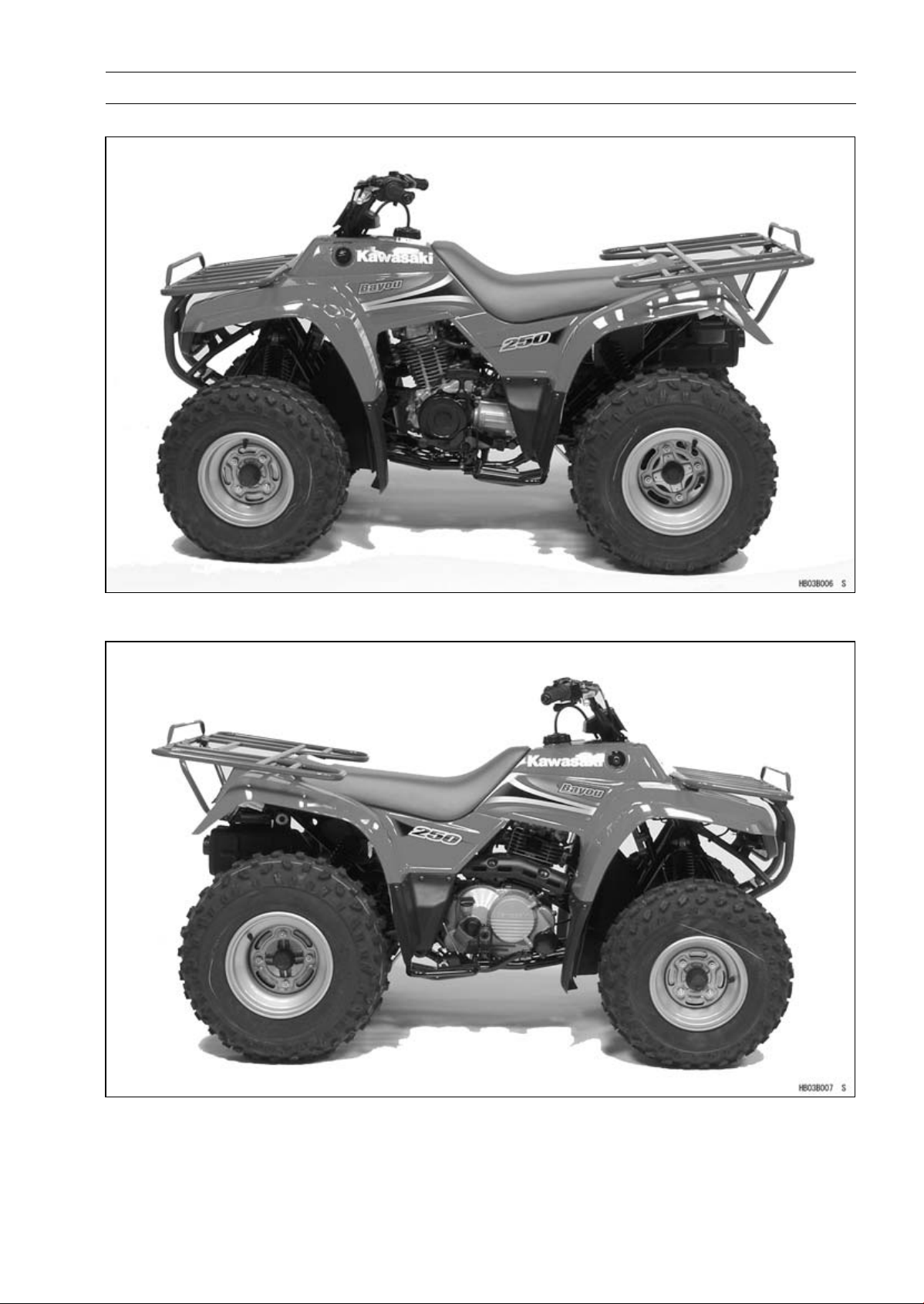
KLF250-A1 Right Side View

1-6 GENERAL INFORMATION
General Specifications
Item KLF250-A1 ∼ A6F
Dimensions
Overall Length 1 780 mm (70.08 in..)
Overall Width 1 120 mm (44.09 in.),
(US) (CA) 1 020 mm (40.16 in.)
Overall Height 1 040 mm (40.94 in.)
Wheelbase 1 115 mm (43.90 in.)
Ground Clearance 155 mm (6.10 in.)
Seat Height 730 mm (28.74 in.)
Dry Mass 185 kg (408 lb), (US) 183 kg (404 lb),
(CA) 183.5 kg (405 lb)
Curb Mass:
Front 89 kg (196 lb), (US) (CA) 88.5 (195 lb)
Rear
Fuel Tank Capacity 10 L (2.6 US gal)
Performance
Minimum Turning Radius 2.7 m (8.86 ft)
Engine
Type 4-stroke, SOHC, 1-cylinder
Cooling System Air-cooled
Bore and Stroke 69.0 × 61.0 mm (2.72 × 2.40 in.)
Displacement
Compression Ratio 8.9
Maximum Horsepower 12.5 kW (17 PS) @7 000 r/min (rpm), (US) –
Maximum Torque 17.9 N·m (1.83 kgf·m, 13.24 ft·lb)
Carburetion System Carburetor, MIKUNI VM24SS
Starting System Electric starter & Recoil starter
Ignition System CDI
Timing Advance Electronically advanced
Ignition Timing
Spark Plug NGK DR8ES
Valve Timing:
Inlet:
Open 35° BTDC
Close 57° ABDC
Duration 272°
Exhaust:
Open 54° BBDC
Close 26° ATDC
Duration 260°
Lubrication System Forced lubrication (wet sump)
106 kg (234 lb), (US) 104.5 kg (230 lb),
(CA) 105 kg (232 lb)
228 cm³ (13.9 cu in.)
@5 500 r/min (rpm)
From 10° BTDC @1 800 r/min (rpm)
to 35° BTDC @4 600 r/min (rpm)

GENERAL INFORMATION 1-7
General Specifications
Item KLF250-A1 ∼ A6F
Engine Oil:
Type
Viscosity
Capacity 2.0 L (2.11 US qt)
Drive Train
Primary Reduction System:
Type
Reduction Ratio 3.450 (69/20)
Clutch Type Wet multi disc and centrifugal
Transmission:
Type 5-speed plus reverse, constant mesh, return shift
Gear Ratio:
1st 2.923 (38/13)
2nd 1.684 (32/19)
3rd
4th
5th 0.785 (22/28)
Reverse 3.115 (27/13 × 33/22)
Final Drive System:
Type Shaft
Reduction Ratio
Overall Drive Ratio (@Top Gear)
Final Gear Case Oil:
Type Hypoid gear oil
Capacity 0.2 L (0.21 US qt)
Frame
Type Double tubular
Caster (Rake Angle) 4.0°
Camber 3.0°
King Pin Angle 10°
Trail 17 mm (0.67 in.)
Tread:
Front 764 mm (30.08 in.)
Rear 776 mm (30.55 in.)
Front Tire:
Type Tubeless
Size AT21 × 8 - 9
Rear Tire:
Type Tubeless
Size AT22 × 10 - 10
API SF or SG
API SH or SJ with JASO MA
SAE 10W-40
Gear
1.173 (27/23)
0.923 (24/26)
4.680 (18/15 × 39/10)
12.686
SAE90 (above 5°C, 41°F) or SAE80 (below 5°C, 41°F)

1-8 GENERAL INFORMATION
General Specifications
Item KLF250-A1 ∼ A6F
Rim size:
Front 9×6.0
Rear 10 × 8.5
Suspension:
Front:
Type Independent swing axle
Wheel Travel
Rear:
Type Torque tube-link
Wheel Travel 125 mm (4.92 i n.)
Brake type:
Front Drum (Mechanical)
Rear Drum (Mechanical)
Electrical Equipment
Battery 12 V 14 Ah, (US) 12 V 11 Ah
Headlight:
Type Semi-sealed beam
Bulb 12 V 25/25 W × 2
Tail/brake light 12 V 8/27 W × 2
Alternator:
Type Three - phase AC
Rated Output 13 A, 14 V @8 000 r/min (rpm)
115 mm (4.53 in.)
Specifications are subject to change without notice, and may not apply to every country.
(CA): Canada Model
(US): U.S.A. Model
Unit Conversion Table
GENERAL INFORMATION 1-9
Prefixes for Units:
Prefix Symbol
mega M × 1 000 000
kilo k ×1000
centi c ×0.01
milli m × 0.001
micro µ × 0.000001
Power
Units of Mass:
kg ×2.205=lb
g × 0.03527 = oz
Units of Volume:
L × 0.2642 = gal (US)
L × 0.2200 = gal (imp)
L × 1.057 = qt (US)
L × 0.8799 =
L×2.113=
L × 1.816 =
mL × 0.03381 = oz (US)
mL × 0.02816 = oz (imp)
mL × 0.06102 = cu in.
qt (imp)
pint (US)
pint (imp)
Units of Force:
N × 0.1020 = kg
N × 0.2248 = lb
kg ×9.807=N
kg ×2.205=lb
Units of Length:
km × 0.6214 = mile
m × 3.281 = ft
mm × 0.03937 = in
Units of Torque:
N·m × 0.1020 = kgf·m
N·m × 0.7376 =
N·m × 8.851 = in·lb
kgf·m
kgf·m
kgf·m × 86.80 = in·lb
× 9.807 = N·m
× 7.233 =
ft·lb
ft·lb
Units of Pressure:
kPa × 0.01020 =
kPa × 0.1450 = psi
kPa × 0.7501 = cmHg
kg/cm² × 98.07 = kPa
kg/cm² × 14.22 = psi
cmHg×1.333=kPa
kg/cm²
Units of Speed:
km/h × 0.6214 = mph
Units of Power:
kW ×1.360=PS
kW ×1.341=HP
PS × 0.7355 = kW
PS
× 0.9863 = HP
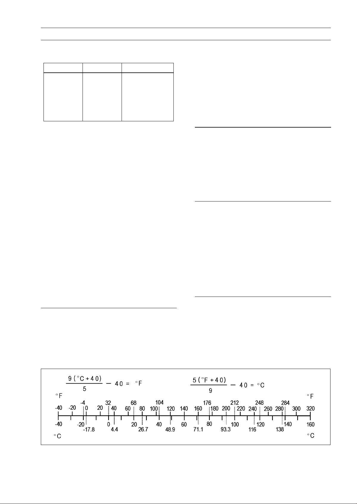
Units of Temperature:


PERIODIC MAINTENANCE 2-1
Periodic Maintenance
Table of Contents
Periodic Maintenance Chart .............. 2-2
Torque and Locking Agent................. 2-3
Specifications .................................... 2-6
Periodic Maintenance Procedures..... 2-7
Fuel System.................................... 2-7
Throttle Lever Free Play
Inspection.................................. 2-7
Throttle Lever Free Play
Adjustment ................................ 2-7
Fuel System Cleanliness
Inspection.................................. 2-8
Air Cleaner E lement Cleaning and
Inspection.................................. 2-8
Air Cleaner Draining..................... 2-9
Fuel Hose and Connection
Check ........................................ 2-9
Fuel Hose Replacement .............. 2-9
Engine Top End .............................. 2-10
Valve Clearance Inspection ......... 2-10
Spark Arrester Cleaning............... 2-10
Clutches .......................................... 2-11
Clutch Adjustment........................ 2-11
Engine Lubrication System ............. 2-12
Engine Oil Change....................... 2-12
Oil Filter Change .......................... 2-12
2
Wheels/Tires................................... 2-13
Tire Inspection ............................. 2-13
Final Drive....................................... 2-14
Final Gear Case Oil Change ........ 2-14
Propeller Shaft Joint Boot
Inspection .................................. 2-14
Brakes............................................. 2-15
Front Brake Adjustment ............... 2-15
Rear (Parking) Brake Lever Free
Play Inspection .......................... 2-16
Brake Pedal Free Play Inspection 2-16
Rear (Parking) Brake Lever and
Pedal Free Play Adjustment...... 2-17
Steering .......................................... 2-18
Steering Inspection ...................... 2-18
Electrical System ............................ 2-18
Battery Inspection ........................ 2-18
Spark Plug Cleaning / Inspection . 2-18
Spark Plug Gap Inspection .......... 2-18
Brake Light Switch Adjustment .... 2-19
General Lubrication ........................ 2-19
Lubrication ................................... 2-19
Bolts and Nuts Tightening............... 2-21
Tightness Inspection .................... 2-21

2-2 PERIODIC MAINTENANCE
Periodic Maintenance Chart
The scheduled maintenance m ust be done in accordance with this chart to keep the v ehicle in good
running condition. The initial maintenance is vitally important and must not be neglected.
FREQUENCY
OPERATION
ENGINE
Air cleaner - service
Throttle lever play - inspect
Valve clearance - inspect
Fuel system cleanliness - inspect*
Engine oil - change*
Oil filter - replace*
Clutch adjustment*
Spark plug - clean and gap
Spark arrester - clean
Fuel hoses and conne
Fuel hose - replace 4 years
CHASSIS
*
ctions - inspect
First
Service
After 10
hrs. or
100 km
(60 mi)
of use
Every 10
days or
200 km
(120 mi)
of use
Every 30
(360 mi)
• •
• •
• •
• •
• •
• •
• •
• •
Regular Service
Every 90
days or
600 km
of use
days or
1 700 km
(1 100 mi)
of use
Every
year of
use
•
•
Joint boots - inspect*
Rear brake pedal and lever adjustment - inspect*
Cables adjustment*
Bolts and nuts - tighten
Brake wear - inspect*
Brake light switch - inspect*
Battery - inspect
Steering - inspect
Tire wear - inspect*
Final gear case oil - change
General lubricatio
*: Service more frequently when operated in mud, dust, or other harsh riding conditions.
: Clean, adjust, lubricate, torque, or replace parts as necessary.
•
n*
• •
• •
• •
• •
• •
• •
• •
• •
•
• •
•

PERIODIC MAINTENANCE 2-3
Torque and Locking Agent
The following tables list the tightening torque for the major fasteners, and the parts requiring use of
a non-permanent locking agent or liquid gasket.
Letters used in the “Remarks” column mean:
L: Apply a non-permanent locking agent to the threads.
MO: Apply molybdenum disulfide oil solution (mixture of the engine oil and molybdenum disulfide
grease in a weight ratio 10 : 1).
S: Tighten the fasteners following the specified sequence.
St: Stake the fasteners to prevent loosening.
Fastener
Fuel Sytem
Carburetor Holder Bolts 11 1.1 95 in·lb L
Throttle Lever Bolt 5.9 0.6 52 in·lb
Engine Top End
Cylinder Head Bolts (M10), first torque
Cylinder Head Bolts (M10), final torque 34 3.5 25 S
Cylinder Head Bolts (M6), first torque 5.9 0.6 52 in·lb MO, S
Cylinder Head Bolts (M6), final torque 9.8 1.0 87 in·lb S
Valve Adjusting Cap Bolts 8.8 0.9 78 in·lb
Retaining Bolt 4.4 0.45 39 in·lb
Compression Releasing Lever Bolt 8.8 0.9 78 in·lb
Camshaft Sprocket Bolt 34 3.5 25 MO
Rear Camshaft Chain Guide Bolt
Camshaft Chain Tensioner Mounting Bolts
Valve Adjusting Screw Locknuts 12 1.2 104 in·lb
Rocker Shaft Retainer Screws 4.4 0.45 39 in·lb
Camshaft Chain Guard Screws 4.4 0.45 39 in·lb
Engine Right Side
Right Engine Cover Bolts
Clutch Spring Bolts
Primary Clutch Hub Nut 127 13 94 MO
Secondary Clutch Hub Nut 78 8.0 58 MO
Balancer Drive Gear Nut 83 8.5 61 MO
Balancer Gear Nut 11 8 12 87 MO
Clutch Adjusting Screw Locknut
Recoil Starter
Recoil Starter Mounting Bolts 8.8 0.9 78 in·lb
Recoil Starter Flange Nut 12 1.2 104 in·lb
Engine Lubrication System
Oil Pipe Banjo Bolts 15 1.5 11
Oil Pump Screws
Engine Drain Plug 29 3.0 22
Oil Filter Cover Bolts 8.8 0.9 78 in·lb
Relief Valve
N·m kgf·m ft·lb
13 1.3 113 in·lb
9.8 1.0 87 in·lb
8.8 0.9 78 in·lb
8.8 0.9 78 in·lb
12 1.2 104 in·lb
11 1.1 95 in·lb
4.4 0.45 39 in·lb
15 1.5 11 L
Torque
Remarks
L(1), MO, S

2-4 PERIODIC MAINTENANCE
Torque and Locking Agent
Fastener
Engine Removal/Installation
Engine Bracket Bolts and Nuts 26 2.7 20
Engine Mounting Nuts (M10) 39 4.0 29
Engine Mounting Nut (M8) 29 3.0 22
Crankshaft/Transmission
Engine Drain Plug 29 3.0 22
Crankcase Bolts 8.8 0.9 78 in·lb
Clutch Release Cam Pin 25 2.5 18 L
Return Spring Pin
Output Shaft Bearing Position Plate Screws 8.8 0.9 78 in·lb L
Relief Valve 15 1.5 11 L
Bearing Stopper Screws 9.8 1.0 87 in·lb
Positioning Lever Bolt 8.8 0.9 78 in·lb
Neutral and Reverse Switch Screws – – – L
Shift Drum Pin Plate Bolt 12 1.2 104 in·lb
Wheels/Tires
Wheel Nuts 34 3.5 25 S
Front Axle Nuts 34 3.5 25
Tie-rod End Nuts 41 4.2 30
Tie-rod Adjusting Sleeve Locknuts 26 2.7 20
Rear Axle Nuts 147 15 108
Final Drive
Output Bevel Gear Case Bolts (M8) 25 2.5 18 L(1)
Output Bevel Gear Case Bolts (M6)
Oil Seal Housing Nuts 25 2.5 18
Drive Gear Nut 118 12 87 MO
Cam Damper Mounting Nut 78 8.0 58 MO
Driven Gear Shaft Nut 147 15 108 L
Bearing Retainer 108 11 80 L
Pinion Gear Nut 69 7.0 51 St
Propeller Shaft Housing Nuts 25 2.5 18
Final Gear Case Drain Bolt 20 2.0 14
Speedometer Plug
Final Gear Case Filler C ap 15 1.5 11
Ring Gear Cover Bolts 25 2.5 18 L
Axle Shaft Pipe Bolts 20 2.0 14
Oil Level Inspection Bolt 7.8 0.8 69 in·lb
Brakes
Front Axle Nuts 34 3.5 25
Rear Axle Nuts 147 15 108
Front Brake Panel Bolts 25 2.5 18 L
Rear Brake Panel Bolts 29 3.0 22 L
Rear Brake Drum Drain Bolts 29 3.0 22
N·m kgf·m ft·lb
25 2.5 18 L
8.8 0.9 78 in·lb
20 2.0 14
Torque
Remarks

Torque and Locking Agent
PERIODIC MAINTENANCE 2-5
Fastener
Suspension
Front Suspension Arm Pivot Bolts 88 9.0 65
Rear Suspension Arm Pivot Bolts and Nuts 34 3.5 25
Shock Absorber Mounting Bolts and Nuts 34 3.5 25
Steering Knuckle Pivot Nuts 39 4.0 29
Steering
Steering Stem Clamp Bolts
Steering Stem Bottom End Nut 29 3.0 22
Tie-rod End Nuts 41 4.2 30
Tie-rod Adjusting Sleeve Locknuts
Steering Knuckle Arm Pivot Nuts 39 4.0 29
Handlebar Holder Bolts 20 2.0 14 S
Frame
Rear Carrier Bolts 20 2.0 14
Electrical System
Alternator Cover Bolts 8.8 0.9 78 in·lb
Spark Plug 14 1.4 10
Starter Motor Clutch Bolts
Ignition Switch Nut
Alternator Rotor Bolt 59 6.0 43
Starter Motor Mounting Bolts
Starter Motor Terminal Nut
Starter Motor Terminal Locknut 6.9 0.7 61 in·lb
Starter Motor Bolts 3.4 0.3 30 in·lb
N·m
26 2.7 20
26 2.7 20
34 3.5 25 L
2.9 0.3 26 in·lb
8.8 0.9 78 in·lb
4.9 0.5 43 in·lb
Torque
Remarks
kgf·m ft·lb
The table below, relating tightening torque to thread diameter, lists the basic torque for the bolts and
nuts. Use this table for only the bolts and nuts which do not require a specific torque value. All of the
values are for use with dry solvent-cleaned threads.
Basic Torque for General Fasteners
Threads Torque
dia. (mm) N·m kgf·m ft·lb
5 3.4 ∼ 4.9 0.35 ∼ 0.50 30 ∼ 43 in·lb
6 5.9 ∼ 7.8 0.60 ∼ 0.80 52 ∼ 69 in·lb
8 14 ∼19 1.4 ∼1.9 10.0 ∼ 13.5
10 25 ∼ 34 2.6 ∼ 3.5 19.0 ∼ 25
12 44 ∼ 61 4.5 ∼ 6.2 33 ∼ 45
14 73 ∼ 98 7.4 ∼ 10.0 54 ∼ 72
16 115 ∼ 155 11. 5 ∼ 16.0 83 ∼ 115
18 165 ∼ 225 17.0 ∼ 23.0 125 ∼ 165
20 225 ∼ 325 23 ∼ 33 165 ∼ 240

2-6 PERIODIC MAINTENANCE
Specifications
Item Standard Service Limit
Fuel System
Throttle Lever Free Pla
Idle Speed 1 300 ∼ 1 400 r/min (rpm) –––
Air Cleaner Element Oil High-quality foam air filter oil –––
Engine Top End
Valve Clearance:
Exhaust 0.18 ∼ 0.23 mm (0.0071 ∼ 0.0091 in.) –––
Inlet 0.15 ∼ 0.20 mm (0.0059 ∼ 0.0079 in.) –––
Engine Lubrication System
Engine Oil:
Type API SF or SG –––
Viscosity SAE10W40 –––
Capacity 2.0 L (2.11 US qt) –––
Wheels/Tires
Tire Tread Depth:
Front ––– 4 mm (0.16 in.)
Rear ––– 4 mm (0.16 in.)
Standard Tire:
Front AT 21 X 8 -9 –––
Rear AT 22 x 10-10 –––
Final Drive
Final Gear Case:
Gear Case Oil:
Type API GL-5 Hypoid gear oil –––
Viscosity SAE90 (above 5°C, 41°F) –––
Capacity 0.2 L (0.21 US qt) –––
Brakes
Front Brake Lever Free Play
Rear (Parking) Brake Lever Free
Play
Brake Pedal Free Play
Cam Lever angle 80 ∼ 90° –––
Electrical System
Spark Plug Gap 0.6 ∼ 0.7 mm (0.024 ∼ 0.028 in.) –––
Rear Brake Light Switch Timing On after 10 mm (0.4 in.) of pedal travel –––
y
2 ∼ 3 mm (0.08 ∼ 0.12 in.) –––
API SH or SJ with JASO MA –––
(When filter is not removed)
2.1 L (2.22 US qt)
(When filter is removed)
2.75 L (2.91 US qt) –––
(When engine is completely dry)
Dunlop, KT856, Tubeless –––
Dunlop, KT857, Tubeless –––
SAE80 (below 5°C, 41°F)
1 ∼ 2 mm (0.04 ∼ 0.08 in.)
2 ∼ 3 mm (0.08 ∼ 0.12 in.) –––
25 ∼ 35 mm (1.0 ∼ 1.4 in.)
–––
–––
–––
–––
Periodic Maintenance Procedures
Fuel System
Throttle Lever Free Play Inspection
Check that the throttle lever moves smoothly from full
•
open to close, and the throttle closes quickly and completely in all steering positions by the return spring.
If the throttle lever does not return properly, check the
throttle cable routing, lever free play, and cable damage.
Then lubricate the throttle cable.
Run the engine at the idle speed, and turn the handlebar
•
all the way to the right and left to ensure that the idle speed
does not change.
If the idle speed increases, check the throttle lever free
play and the cable routing.
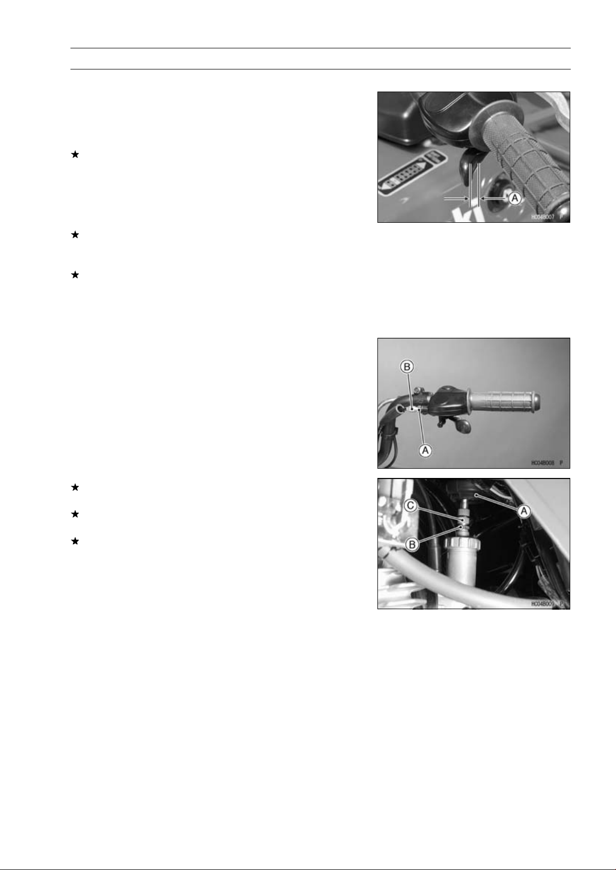
Stop the engine and check the throttle lever free play [A].
•
If the free play is not within the specified range, adjust the
cable.
Throttle Lever Free Play
Standard: 2 ∼ 3 mm (0.08 ∼ 0.12 in.)
PERIODIC MAINTENANCE 2-7
Throttle Lever Free Play Adjustment
Slide the rubber cover off the adjuster at the throttle case.
•
Loosen the locknut [A] and turn the throttle cable upper
•
adjuster [B] until the cable has proper amount of play.
Tighten the locknut and reinstall the rubber cover.
•
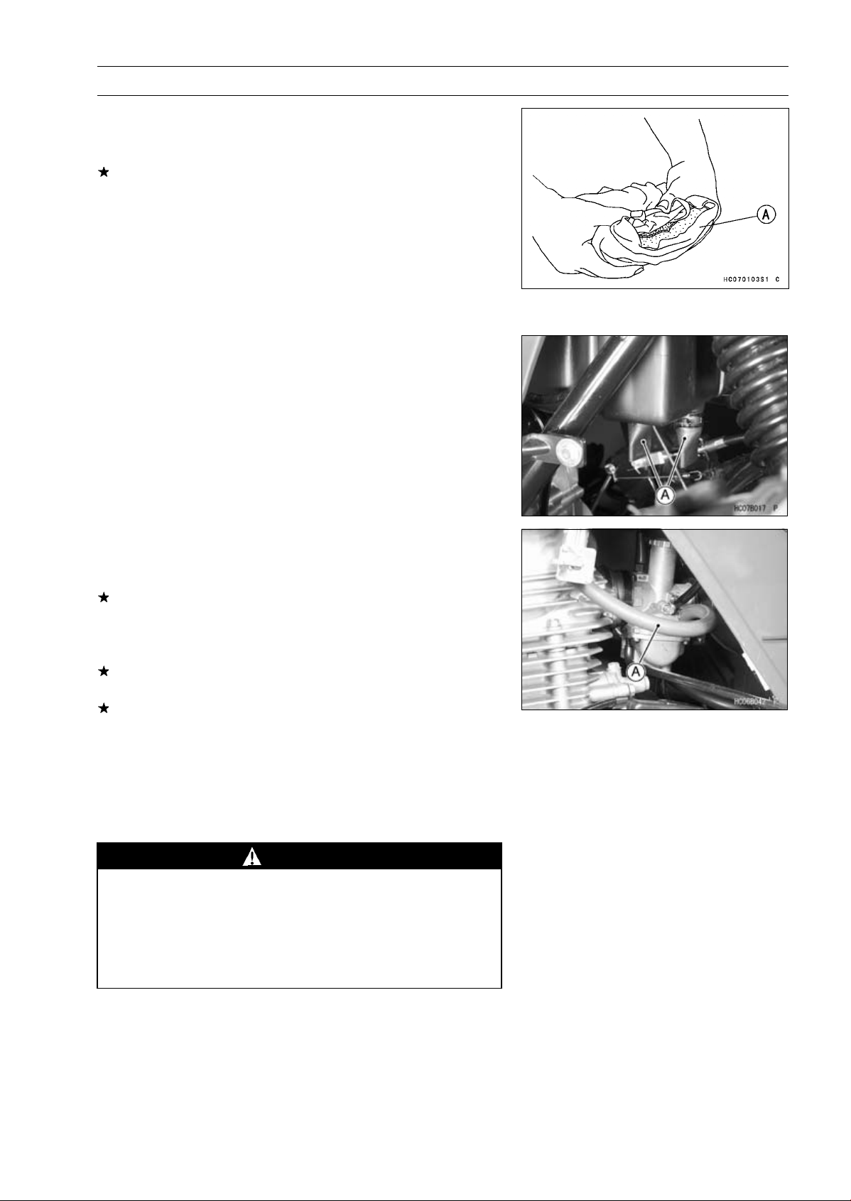
If the free play cannot be adjusted by using the upper cable adjuster, pull up the rubber cover [A] at the carburetor.
Loosen the locknut [B] and turn the throttle cable lower
adjuster [C] to obtain the specified free play.
Tighten the locknut and reinstall the rubber cover.
2-8 PERIODIC MAINTENANCE
Periodic Maintenance Procedures
Fuel System Cleanliness Inspection
WARNING
Gasoline is extremely flammable and can be explosive under certain conditions. Turn the ignition
switch OFF. Do not smoke. Make sure the area is
well ventilated and free from any source of flame
or sparks; this includes any appliance with a pilot
light.
Turn the fuel tap to the OFF position.
•
Run the lower end of the carburetor drain hose to a suit-
•
able container.
Turn out the carburetor drain plug a few turns and drain
•
the fuel system.
Check to see if water or dirt comes out.
•
Tighten the drain plug.
•
If any water or dirt appears during the above inspection,
clean the fuel system (carburetor, tank, fuel hose).
Air Cleaner Element Cleaning and Inspectio n
NOTE
In dusty areas, the element should be cleaned more
○
frequently than the recommended interval.
After riding through rain or muddy terrains, the element
○
should be cleaned immediately.
Since repeated cleaning opens the pores of the ele-
○
ment, replace it with a new one in accordance with the
Periodic Maintenance Chart.
Also, if there is a break in the element material or any
○
other damage to the element, replace the element with
a new one.
WARNING
Clean the element in a well-ventilated area, and
take care that there are no sparks or flame anywhere near the working area; this includes any
appliance with a pilot light. Because of the danger
of highly flammable liquids, do not use gasoline or
a low-flash point solvent to clean the fo am element.
Remove the air cleaner element (see Air Cleaner Element
•
Removal).
Clean the element in a bath of high-flash point solvent
•
using a soft bristle brush.
Periodic Maintenance Procedures
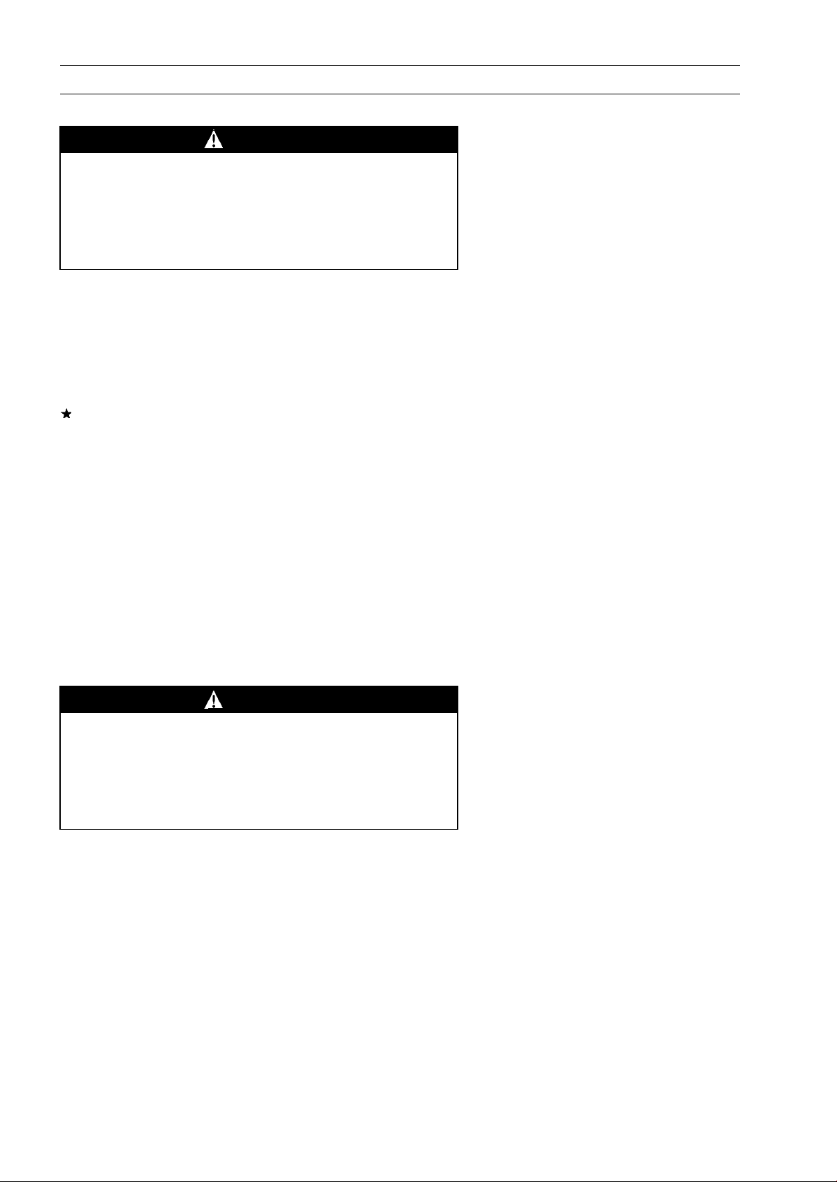
Squeeze it dry in a clean towel [A]. Do not wring the ele-
•
ment or blow it dry; the element can be damaged.
Inspect the element for damage.
•
If it is torn, punctured, or hardened, replace it.
NOTE
Replace the element after cleaning it five times or if it is
○
damaged.
After cleaning, saturate the element with a high-quality
•
foam-air-filter oil, squeeze out the excess oil, then wrap
it in a clean rag and squeeze it as dry as possible. Be
careful not to tear the element.
Air Cleaner Draining
Two drain tubes [A] are connected to the bottom of the
air cleaner housing to drain water or oil accumulated in the
housing.
Squeeze open the two drain tubes to expel dust and/or
•
water accumulated inside.
PERIODIC MAINTENANCE 2-9
Fuel Hose and Connection Check
Turn the fuel tap to the OFF position.
•
Check the fuel hose [A].
•
If the fuel hose is frayed, cranked, or bulged, replace the
fuel hose.
Check that the hose is securely connected and clamps
•
are tightened.
If the fuel hose has been sharply bent or kinked, replace
the fuel hose.
If the clamps are loosened or damaged, replace the
clamps.
When installing the fuel hose, avoid sharp bending, kink-
•
ing, flattening or twisting, and route the fuel hose with a
minimum of bending so that the fuel flow will not be ob-
structed.
Fuel Hose Replacement
WARNING
Gasoline is extremely flammable and can be ex-
plosive under certain conditions. Turn the ignition
switch OFF. Do not smoke. Make sure the area is
well ventilated and free from any source of flame
or sparks; this includes any appliance with a pilot
light.
Turn the fuel tap to the OFF position.
•
Remove:
•
Clamps
Fuel Hose
2-10 PERIODIC MAINTENANCE
Periodic Maintenance Procedures
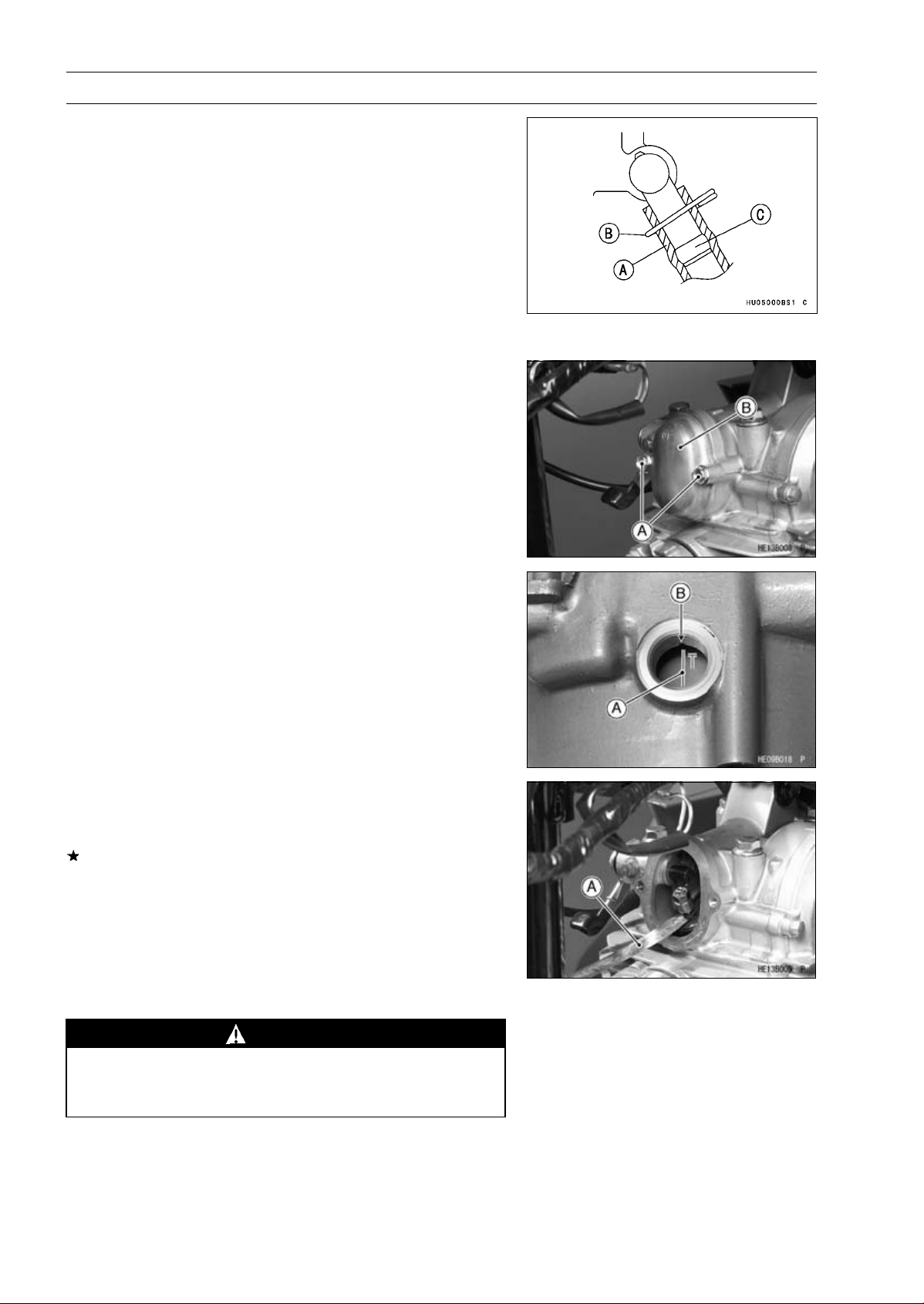
Fit the fuel hose [A] onto the pipe fully and install the
•
clamps [B] beyond the raised rib [C].
Engine Top End
Valve Clearance Inspection
NOTE
Check the valve clearance only when the engine is cold
○
(at room temperature).
Remove:
•
Front Fender (see Frame chapter)
Bolts [A] and Valve Adjusting Caps [B]
Remove:
•
Recoil Starter (see Recoil Starter chapter)
Timing Inspection Plug
Turn the crankshaft counterclockwise with a wrench on
•
the alternator rotor bolt until the “T” mark [A] on the alternator rotor aligns with the slot [B], as shown.
Measure the clearance of each valve between the end of
•
the valve stem and the adjusting screw on the rocker arm
with a thickness gauge [A].
If the v alve clearance is not correct, adjust it.
Valve Clearance (when cold)
Exhaust:
Inlet:
Spark Arrester Cleaning
0.18 ∼ 0.23 mm (0.0071 ∼ 0.0091 in.)
0.15 ∼ 0.20 mm (0.0059 ∼ 0.0079 in.)
WARNING
To avoid burns, wear gloves while cleaning the
spark arrester. Since the engine must be run during this procedure, the muffler will become hot.
 Loading...